1
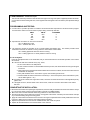
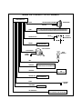
AS - 9151N
Remote Car Starter
Installation Instructions
For installation in vehicles with 12 volt negative ground circuits,
gasoline engines, with automatic transmission only!
KIT CONTENTS
(1) Remote Start Control Module
(2) Wiring Harnesses
(1) Parts Bag Containing
(2) Fuses
(1) Ring Terminal
(2) Fuse Holders
(4) 1/2" Long Screws
(1) Control Switch (1) Pin Switch
(1) Hood Diode Bridge
(1) Literature Package
(1) RF Antenna Extender (AS-9166)
Form No. 128-4500B
The AS-9151N is for Automatic Transmission vehicles only! Although it is a sophisticated system, with multiple built-in
safety features, it must not be installed into vehicles with manual transmissions. Doing this can cause serious personal
injury and property damage.
IMPORTANT ! DO NOT PLUG THE SIX PIN MAIN POWER HARNESS OR THE 12 PIN INPUT / OUTPUT HARNESS
INTO THE REMOTE START CONTROL MODULE UNTIL ALL CONNECTIONS HAVE BEEN MADE TO THE VEHICLE.
WIRING CONNECTIONS: 6 Pin Main Power Harness
1. RED w/ WHITE Tracer Wire : + 12 VDC Battery 1 Source
Connect this wire to a + 12 VDC constant source. Using the 30 A fuse provided, connect this wire to the positive
terminal of the vehicle's battery.
The Battery 1 source provides + 12 volts to the AS-9151N module for Ignition 1 output, Ignition 2 output, and circuit
logic.
2. RED Wire : + 12 VDC Battery 2 Source
Connect this wire to a + 12 VDC constant source, but not the same source as the battery 1 wire, unless connecting
directly to the battery terminal. Using the 30 A fuse provided, connect this wire to the positive terminal of the vehicle's
battery.
The Battery 2 source provides + 12 volts to the AS-9151N module for Starter output and Accessory output.
3. YELLOW Wire : Starter Output
Connect this wire to the starter wire from the ignition switch harness. This wire will show +12 Volts when the ignition
key is turned to the “ START or CRANK “ position, and 0 Volts when the ignition key is in any other position.
NOTE: If installing the AS-9151N with an alarm that utilizes a starter cut relay, make sure the Yellow wire is connected
to the “ starter “ side of the relay contacts, and not the “ switch “ side.
When installing the AS-9151N into vehicles with a factory installed security system, connect the Yellow wire between
the output of the starter cut relay and the neutral safety switch.
4. BLUE Wire : Ignition 1 Output
Connect this wire to the ignition 1 wire from the ignition switch harness. This wire will show +12 Volts when the ignition
key is turned to the “ RUN or ON “ and the “ START or CRANK “ positions, and 0 Volts when the key is turned to
the “ OFF “ and “ ACCESSORY “ positions.
5. LIGHT GREEN Wire : Ignition 2 Output
Connect this wire to the ignition 2 wire from the ignition switch. This wire will show +12 Volts when the ignition key
is turned to the “ RUN or ON “ position, and in some cases, the “ START or CRANK “ position. This wire will show
0 Volts when the key is turned to the “ OFF “ and “ ACCESSORY “ positions.
NOTE: Some older vehicles may not require the second ignition wire.
6. VIOLET Wire : Accessory Output
Connect this wire to the accessory wire from the ignition switch. This wire will show +12 Volts when the ignition key
is turned to the “ ACCESSORY “ and “ RUN or ON “ positions, and 0 Volts when the key is turned to the “ OFF “ and
“ START or CRANK “ positions.
WIRING THE 6 PIN MAIN POWER HARNESS
REDw/WHITETRACE
WIREFROMAS-9151N
REDWIRE
FROMAS-9151N
VIOLETWIRE
FROMAS-9151N
LT.BLUEWIRE
FROMAS-9151N
IGNITION SWITCH KEY POSITION
SPLICE(TYP.)
OFF
ACCESSORY
ON / RUN
START
BATT 1
BATT 2
ACC
IGN 1
IGN 2
SEE"WIRINGTHE12PINCONNECTOR"LT.BLUEWIREIFREQUIRED.
LT.GREENWIRE
FROMAS-9151N
YELLOWWIRE
FROMAS-9151N
IGN 3
*START
*
+12 VDC IN KEY POSITION INDICATED
MAY BE +12 VDC IN KEY POSITION INDICATED
THIS CIRCUIT IS NOT ALWAYS REQUIRED FOR INSTALLATION
WIRING CONNECTIONS: 12 Pin Input / Output Harness
1. BLACK Wire: Chassis Ground Source
Connect this wire to a solid, clean chassis ground source.
2. DARK BLUE Wire: Remote Start Signal Input
Connect this wire to the pulsed ground output from the remote alarm system. In most cases, it will be connected to
the second or third channel output from the alarm. When the Dark Blue wire receives a ground pulse, the vehicle will
start.
3. BLACK w/WHITE Tracer Wire: Control Switch
The Black w/ White tracer wire provides ON-OFF control of the Remote Starter.
When the Black w/ White wire is switched to a full time ground, the AS-9151N Remote Start Module is operative. When
the Black w/ White wire is at open circuit through the control switch, the remote starter is disabled.
Connect the Black w/ White tracer wire to one of the terminals from the back of the control switch. Connect the
remaining terminal on the control switch to chassis ground. Always try to mount the switch so that the ON position
is in an upward direction.
4. GREY Wire: Negative Inhibit Input 1
Connect this wire to the existing hood pin switch from the alarm system, using the diode bridge included in the package.
Wire the diode bridge as shown in the illustration below. Any time the Grey wire is grounded, the Remote Starter will
stop operating, even if the signal is received from the alarm.
EXISTING HOOD PIN SWITCH
GREY WIRE FROM REMOTE
START HARNESS
DIODE BRIDGE ASSEMBLY
FEMALE BULLET TERMINAL
RED BUTT
CONNECTOR
EXISTING ALARM
PIN SWITCH WIRE
(2) IN4001
DIODES
MALE BULLET
IMPORTANT ! If the alarm system does not incorporate a hood pin switch, you must add a switch to the Remote Start
system. This is an important safety feature of the AS-9151N Remote Starter, and failure to use this feature can result in
serious injury.
5. GREY w/ BLACK Tracer Wire: Negative Inhibit Input 2
Any time the grey w/ black tracer wire is grounded, the Remote Starter will stop operating, even if the signal is received
from the alarm.
If the brake light switch in the vehicle switches ground to the brake light circuit, connect the Grey w/ Black trace wire
to the output of the brake light switch. If the brake light switch in the vehicle switches +12 Volts, do not use the Grey
w/ Black wire; see Brown w/ White tracer wire.
6. BROWN Wire: Positive Inhibit Input 1
Any time + 12 Volts is applied to the Brown wire, the Remote Starter will stop operating, even if the signal is received
from the alarm.
If the vehicle has a factory installed hood pin switch, and that switch provides + 12 Volts to an under hood light, the
Brown wire can be connected to the existing pin switch.
7. BROWN w/ BLACK Tracer Wire: Positive Inhibit Input 2
Any time + 12 Volts is applied to the Brown w/ Black tracer wire, the Remote Starter will stop operating, even if the signal
is received from the alarm. If the brake light switch in the vehicle switches + 12 Volts to the brake light circuit, connect
the Brown w/ Black trace wire to the output of the brake light switch. If the brake light switch in the vehicle switches
ground, do not use the Brown w/ Black wire; see Grey w/ Black tracer wire.
8. YELLOW w/ BLACK Tracer Wire: + 12 Volt Alarm By - Pass Output
This wire provides a 500 mA + 12 Volt transistorized output when the ignition key is turned to the “ON” position, and
0 Volts when the ignition key is “OFF” and when the vehicle is running under the control of the remote starter.
This wire should be connected to the ignition input of the alarm system (Yellow wire for Audiovox alarms).
NOTE: You must disconnect the ignition input of the alarm from any other wire that it is presently connected
to in the vehicle.
The Yellow w/ Black wire output will allow you to remote start the vehicle while leaving the alarm armed.
9. (2) WHITE Wires: Parking Light Flasher
These wires are the COMMON and NORMALLY OPEN contacts of the on-board parking lamp relay.
If the vehicle's parking lights are a +12 volt switched system, connect (1) of the White wires to a fused (at least 15A)
+12 volt battery source, and connect the second White wire to the vehicle's parking light wire.
If the vehicle's parking lights are a chassis ground switched system, connect (1) of the White wires to a chassis ground
source, and connect the second White wire to the vehicle's parking light wire.
10.LIGHT BLUE Wire: Ignition 3 / Shock Disable Output
This is a 500 mA transistorized ground output, and an external relay will be required in all cases that this output is
needed.
NOTE: This Light Blue wire is energized 3 seconds before starting and remains energized for 4 seconds after
shut down.
The Light Blue output serves the following functions.
A. Shock Sensor Override: If the alarm is connected to a shock sensor, then the vibration caused by remote starting
the vehicle may trip the alarm. If this is the case, connect the Light blue wire to terminal 86 of an external relay.
Connect terminal 85 of the relay to a fused + 12 Volt battery source. Cut the trigger wire from the shock sensor, and
connect one side of the cut wire to terminal 30 of the relay. Connect the other side of the cut wire to terminal 87a
of the relay. Just before the remote starter is activated, the relay contacts will open, and the shock sensor will not
trip the alarm.
B. Ignition 3 Output: Some newer vehicles use a third ignition wire, which is necessary to keep the engine running.
If this is the case, connect the Light Blue wire to terminal 86 of an external relay. Connect terminals 85 and 30 together
to a + 12 Volt battery source that is fused for a minimum 25 A rating. Connect terminal 87 of the external relay to
the third ignition wire in the vehicle.
C. G.M. VATS Key Override: If the vehicle has the General Motors VATS system installed, you will need to by-pass the
starter cut portion of the VATS system. To do this;
1. Measure the resistance of the ignition key, and get a resistor whose value is within 5% of the key value.
2. Locate the pair of VATS wires in the vehicle, usually running from the ignition switch to the passenger side of the
vehicle.
NOTE: These wires are typically White w/ Black tracer and Violet w/ Yellow tracer, however in late model Cadillacs,
they are run through an Orange sleeve, and are either both Black, both Yellow, or both White wires.
3. Connect the Light Blue wire from the Remote Starter to terminal 86 of an external relay. Connect terminal 85 of
the relay to a fused + 12 Volt battery source.
4. Cut (1) of the VATS wires, and connect the ignition switch side of the cut wire to terminal 87a of the relay. Connect
the other side of the cut wire to terminal 30 of the relay.
5. Connect the resistor from terminal 87 of the relay to the second VATS wire.
VATS WIRE #2
MATCHING RESISTOR
87
VATS WIRE #1 (CUT)
TOWARDS IGNITION SWITCH
LIGHT BLUE IGN.3 WIRE FROM
REMOTE START MODULE
87a
86
30
85
VATS WIRE #1 (CUT)
TOWARDS VATS MODULE
TO FUSED +12 VDC
BATTERY SOURCE
Multi Coil Pack Adaptor:
The multi coil pack adaptor is designed for use with vehicles having multiple ignition coils where a single point tach
signal is unavailable.
To use the adaptor, the Green/Black wires must connect to the negative side of the ignition coil(s).
1. For vehicles utilizing independent coils per cylinder, connect the three Green/Black leads to alternate coils. To
achieve optimum performance the coil signals must be evenly distributed. This is done by first mapping out the
firing order of the engine in groups as indicated below. Draw a circle around any of the columns. The Green/Black
wires should be connected to the negative (-) terminal of the respective cylinder number which appears in any of
the circles.
2. For vehicles utilizing 2 cylinder firing per coil pack, connect Green/Black to the tach side of each coil pack. For 8
cylinder, four coil systems, connect to any of the three coils.
3. Connect the Yellow wire to a +12 volt ignition 1 source. This wire must have +12 volts with the ignition in the on and
start position and have 0 volts with the ignition in the off position.
4. Connect the Green wire to the (Green) tach input of the remote start unit.
11.DARK GREEN Wire: Tach Sensor Input
This wire will continually monitor the tach rate while the engine is running under power supplied by the Remote Starter.
Connect this wire to the existing tach wire, or the negative side of the ignition coil in the vehicle. (See dip switch settings
below).
PROGRAMMING AND TESTING:
1. You will notice a 4 position dip switch on board the remote start module. Dip switch #1 and #2 are used to program
the Tach Rate. Refer to the chart below for proper setting of these dip switches.
SW #1
ON
ON
OFF
OFF
SW #2
OFF
ON
ON
OFF
CYLINDERS
4
6
8
12
2. Dip switch #3 controls the run time of the AS-9151N.
ON = 10 Minute Run Time
OFF = 15 Minute Run Time
3. Dip switch #4 controls the operation of the on board parking light flasher relay. This feature provides visual
confirmation whenever the vehicle is running under the control of the remote starter.
ON = Parking lights flash while the vehicle is running
OFF = Parking lights turn on steady while the vehicle is running
4. Test the System:
Press the appropriate button on the transmitter, that you have selected for the remote start operation. If the vehicle
did not start;
A. If the remote start did not activate in any way, check;
1. Is the control switch in the ON position.
2. Is there a solid connection on the Dark Blue remote input wire, and did the alarm send the ground signal
to this wire.
3. Verify that the fuses in the Red and Red w/ White tracer wires are not blown, and the connections onto the
fuseholders are adequate.
4. Verify that the Black wire is connected to a good, clean chassis ground source.
5. Check all inhibit circuits that have been connected, (i.e. is the hood opened, is the transmission in park,
are the brake lights on...etc.).
B. If the starter motor cranked, but engine did not start, check the connection and location of the Light Blue primary
ignition wire.
C. If the lights turned on, but the starter motor did not crank, check the connection and location of the Yellow
start wire.
COMPLETING THE INSTALLATION:
1. Mount the control switch in the passenger compartment, where it is easily accessible to the driver of the vehicle. Always
try to mount the switch so that the upward position is the ON or CLOSED position.
2. Mount the control module behind the dash using cable ties or sheet metal screws.
3. Securely tie all wiring up and away from all hot or moving parts of the vehicle. It is always recommended to use split
vinyl convoluted tubing along wire routing paths.
4. Apply the Caution label included in the kit to an area in the engine compartment that is clearly visible when the hood
is opened. Make sure the surface is clean before applying the label.
5. Replace all panels that were removed for installation ease, and re-test the system.
6. Explain all activated features of the remote starter to the customer.
WIRING THE 12 PIN INPUT / OUTPUT HARNESS
12PINCONNECTOR
EXISTINGPARKINGLAMPWIRE
WHITE
PARKINGLAMP
SPLICE
WHITE
TO+12VOLTBATTERYFORPOSITIVESWITCHEDPARKINGLIGHTS
TOCHASSISGROUNDFORNEGATIVESWITCHEDPARKINGLIGHTS
SPLICE
BROWNw/BLACK
BROWN
EXISTING
BRAKESWITCH
POSITIVEINHIBIT1
CONTROLSWITCH
BLACKw/WHITE
HOOD
PINSWITCH
CHASSIS
GROUND
GREY
DARKBLUE
REMOTETRIGGERTOGROUNDPULSE
(CHANNEL2OR3)OUTPUTFROMALARM
IGNITION3
OR
SHOCKBY-PASS
LIGHTBLUE
GREYw/BLACK
NEGATIVEINHIBIT2
BLACK
DARKGREEN
YELLOWw/BLACK
TOCHASSIS
GROUND
TACH
TOALARM'SIGNITIONINPUT(YELLOWWIREOFAUDIOVOXALARMS)


![取扱説明書[F-CL338] (3.67 MB/PDF)](http://vs1.manualzilla.com/store/data/006679003_2-7a789e1fffad8a1736cf3c3609a77ee7-150x150.png)
![取扱説明書[F-CK338]](http://vs1.manualzilla.com/store/data/006693425_2-c519a1b8843f172b74c3f843cbbd7606-150x150.png)