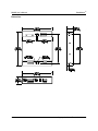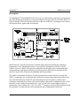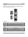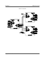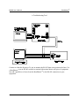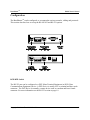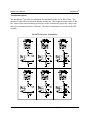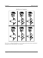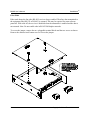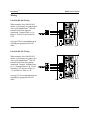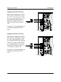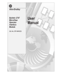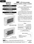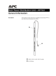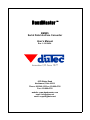
1
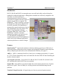
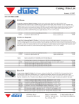
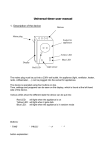
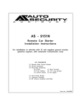
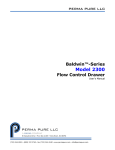
BaudMaster
BM485
Serial Data Interface Converter
User’s Manual
Rev. 1.0 6/28/04
Innovative I/O Since 1977
6979 Wales Road
Northwood, Ohio 43619
Phone: 800-248-1632 or 419-666-4700
Fax: 419-666-4702
website: www.baudmaster.com
email: [email protected]
email: [email protected]
BaudMaster
TM
BM-485
Isolated Serial Data Interface Converter
User’s Manual
5 Year Warranty
Interface converter products, sold by duTec, Inc., are warranted against defects in materials and workmanship for
five years from the date of purchase. There are no other express or implied warranties and no warranty of
merchantability or fitness for a particular purpose.
During the warranty period, duTec will repair or, at its option, replace components that prove to be defective,
provided the unit is shipped prepaid to the manufacturer directly or via and authorized distributor. Not covered by
this warranty are defects caused by modification, misuse or accidents and any further damage caused by inadequate
packing for service return.
duTec’s obligation is restricted to the repair or replacement of defective parts and under no circumstances will duTec
be liable for any other damage, either direct or consequential.
Trademarks
The duTec logo, BaudMasterTM, ADFCTM, Omni-isolationTM and I/O PLEXER are trademarks of duTec, Inc.
Notice to the User
The information contained in this manual is believed to be correct. However, duTec, Inc. assumes no responsibility
for any inaccuracies.
Information in this document is subject to change without notice. No part of this document may be reproduced or
transmitted in any form or by any means, electronic or mechanical, for any purpose, without the express written
permission of duTec, Inc.
Copyright © 2004 duTec, Inc. All rights reserved.
Table of Contents
Introduction . . . . . . . . . . . . . . . . . . . . . 1
Features . . . . . . . . . . . . . . . . . . . . . . . 1-2
Specifications . . . . . . . . . . . . . . . . . . 3-4
Description . . . . . . . . . . . . . . . . . . . 5-12
Configuration . . . . . . . . . . . . . . . . 13-16
Wiring . . . . . . . . . . . . . . . . . . . . . . 17-20
Ordering Information . . . . . . . . . . . . 23
Cable . . . . . . . . . . . . . . . . . . . . . . . . . . 25
BaudMasterTM
BM485 User’s Manual
Introduction
RS-232, RS-485 and RS-422 are among the most successful and widely used serial interface
standards for industrial applications. Although these standards are not directly compatible with
each other, it is often necessary to
communicate between them. In order to
convert RS-232 signals to RS-485 or RS-422
signals a special device is required. The
BaudMasterTM family of interface converters
are designed to easily convert data between
all of these standards. The BaudMasterTM
automatically controls the direction of serial
data eliminating the need for software flow
control. Using a patented technique
(Automatic Data Flow Control, ADFCTM),
BaudMasterTM interface converters
automatically adapt to any baud rate up to
115,200 baud and is independent of
communications protocol. The BaudMasterTM
can be used in your industrial applications
without any hardware or software changes.
Features
Omni-IsolationTM Optical and transformer isolation technology provide up to 2000 volts of
signal and ground isolation between the computer and equipment. Eliminates ground loops that
destroy computer ports and reduce serial communications reliability. (See page 5)
ADFCTM ADFCTM (Automatic Data Flow Control), uses a technique protected by U.S. patent
no. 5,729,547 that automatically senses and controls the direction of RS-485 data eliminating the
need for software control.
3-in-1 Signal Conversion Converts RS-232 to RS-485, RS-232 to RS-422 or RS-485 to RS422. Automatically senses RS-422 four-wire operation.
Status LEDs Status LEDs are provided on both sides of the isolation for the Power, Transmit
and Receive signals. These are handy for verifying operation and troubleshooting network
problems.
Transient Voltage Protection All signal and power lines are protected against transient
Copyright © 2004 duTec 1-800-248-1632
1
BaudMasterTM
BM485 User’s Manual
voltages.
Switch Selectable Termination and Bias Resistors Network termination and bias can easily
be configured with DIP switches available from the outside the converter case. The switches are
clearly identified on the label for easy setup.
DTE-DCE Selection A switch easily makes the BaudMasterTM either a DTE or a DCE device
so the unit will communicate with a DCE or DTE device, or operate with a “straight-through” or
“null modem” cable.
Echo With the echo feature enabled, data is echoed back to the equipment side port. This may
desirable or required with some protocols. The default is no echo.
Baud Rate Independent No switches or jumpers to set. Automatically adapts to all standard
and non-standard baud rates up to 115,200 baud.
Versatile Power Supply The unit can be powered by a wide range of AC or DC voltages.
Wall-plug adapters are available from duTec or others. A pluggable screw terminal is also
provided for use with other power supplies. 7 to 24 volts AC or 9 to 36 volts DC @ 170mA max.
Pluggable Terminal Blocks Industrial rated pluggable terminal blocks for ease of installation
or removal. Accepts up to 16 AWG wire.
DIN Rail Mounting DIN Rail mounting accessories available for easy wiring.
2
Copyright © 2004 duTec 1-800-248-1632
BaudMasterTM
BM485 User’s Manual
Specifications
Isolation
Omni-isolationTM provides 4-way isolation using optical and transformer technology.
Equipment-to-Line, Equipment-to-Power, Line-to-Power, Equipment-to-Chassis,
Line-to-Chassis, Power-to-Chassis.
Hi-Pot: 2000 VRMS for 1 minute, 5500 VDC for 1 second
Leakage Current: Less than 50uA @ 2000 VAC / 60 Hz; 5500 VDC
Baud Rate
0 to 115.2K bps
Range
4000 feet (1220 meters) @ 38.4K bps with 24 AWG twisted pair
Weight
12.8 oz. (363 grams)
Power
9 to 24 volts AC or DC @ 170mA (max)
Enclosure
18 gage Stainless Steel
Dimensions
Height: 4.60 inches (117mm)
Depth: 4.16 inches (106mm)
Width: 1.00 inch ( 25mm)
RS-485/422
Supports RS-422, 4 or 2 wire and RS-485, Auto Detect
Input Resistance: 12K to 15K ohms (1 unit load)
Drive: Up to 32 unit loads (1 unit load = 12K ohms)
Connector: Pluggable Terminal Blocks (#16 to #24 AWG)
Biasing Resistors: Selectable 100K or 1.2K ohms
Terminating Resistors: Selectable NONE, AC or DC
RS-485 Enable
Automatic. Patented ADFCTM technology automatically controls data direction flow.
RS-232
Supports TxD, RxD, DTR, DSR, RTS, CTS, DCD;
Connector: DB9 Male or Female
DCE or DTE selectable
Operating Temperature
-20°C to +80°C
Storage Temperature
-45°C to +100°C
Humidity
5% to 95% RH
Compliance
Pending (CE, FCC Class A, CUL, UL Safety Class II)
Accessories
DIN Rail Mounting Kit: Part No DA-01
AC Power Adapter: North American: 120 VAC Input
AC Power Adapter: European: Universal Input: 90-264 VAC Input
Surge Protection
600 Watt Transient Voltage Suppression on RS-485/422 inputs and outputs, RS-232
inputs and outputs and Power input.
Indicators
Equipment Side: Power, RxD, TxD LEDs
Line Side: Power, RxD, TxD LEDs
Copyright © 2004 duTec 1-800-248-1632
3
BM485 User’s Manual
BaudMasterTM
Dimensions
4
Copyright © 2004 duTec 1-800-248-1632
BaudMasterTM
BM485 User’s Manual
Description
The BaudMasterTM Model BM485-UIP is our most versatile interface converter. It can operate in
one of the following six modes as a converter, isolator or repeater: RS-232 to RS-485, RS-232 to
RS-422, RS-485 to RS-422, RS-485 to RS-485 or RS-422 to RS-422. The diagram below shows
the function blocks, signal paths and isolation.
Omni-isolationTM provides full galvanic isolation using optical and transformer technology:
Equipment-to-Line, Equipment-to-Power, Line-to-Power, Equipment-to-Chassis, Line-toChassis, Power-to-Chassis. Full galvanic isolation breaks the signal, power and ground paths
using transformer and optical technology by allowing data to flow between systems, but not
electrical current. This eliminates all grounding and surge problems.
The ADFCTM (Automatic Data Flow Control) function block controls the flow of serial data.
ADFCTM technology uses a technique that continuously monitors data and automatically senses
and controls the direction of RS-485 data eliminating the need for software control. Other
techniques control the flow of data with a precision timer that must be configured for the correct
baud rate or only enables the transmitter on a “one” bit and relies on the biasing resistors to
maintain the correct voltage for a “zero” bit. ADFCTM is superior to both of these methods in that
the transmitter is enabled for the entire transmission and is independent of baud rate.
Copyright © 2004 duTec 1-800-248-1632
5
BaudMasterTM
BM485 User’s Manual
LED Indicators
Depending on the model, the BaudMasterTM has up to six status LED indicators. These
indicators show the status of data communications and power and are handy for verifying
operation and troubleshooting network problems.
Equipment Side
LED Name
LED Function
+5V
Red indicates the Equipment Side power is on.
TxD
Transmit - Red indicates that the Equipment Side is sending data to the port.
RxD
Receive - Red indicates that the Equipment Side is sending data to the Line Side.
Line Side
LED Name
6
LED Function
+5V
Red indicates the Line Side power is on.
TxD
Transmit - Red indicates that the Line Side is sending data to the port.
RxD
Receive - Red indicates that the Line Side is sending data to the Equipment Side.
Copyright © 2004 duTec 1-800-248-1632
BaudMasterTM
BM485 User’s Manual
Typical Applications
Isolators C Repeaters C Converters
Copyright © 2004 duTec 1-800-248-1632
7
BaudMasterTM
BM485 User’s Manual
Short Haul Modems
8
Copyright © 2004 duTec 1-800-248-1632
BaudMasterTM
BM485 User’s Manual
Line Extenders
Copyright © 2004 duTec 1-800-248-1632
9
BaudMasterTM
BM485 User’s Manual
RS-485 Y Networks
10
Copyright © 2004 duTec 1-800-248-1632
BaudMasterTM
BM485 User’s Manual
RS-422 Y Networks
Copyright © 2004 duTec 1-800-248-1632
11
BaudMasterTM
BM485 User’s Manual
A Troubleshooting Tool
Connect to either the Rx pair or Tx pair to monitor the RS-422 data at any point on the lines. Use
a BaudMasterTM on an RS-485 network to monitor bidirectional data to any piece of equipment.
Just add a parallel set of wires from the BaudMasterTM to the RS-485 connection on your
equipment.
12
Copyright © 2004 duTec 1-800-248-1632
BaudMasterTM
BM485 User’s Manual
Configuration
The BaudMasterTM can be configured to accommodate various networks, cabling and protocols.
This section describes how to set up the RS-485/422 and RS-232 options.
DCE/DTE Switch
The RS-232 port can be configured as a DTE (Data Terminal Equipment) or DCE (Data
Communications Equipment) device. A DTE device is usually a PC or terminal and has a male
connector. The DCE device is normally a remote device such as a modem and has a female
connector. For more information see the RS-232 section on page 19.
Copyright © 2004 duTec 1-800-248-1632
13
BaudMasterTM
BM485 User’s Manual
Termination Options
The BaudMasterTM provides several options for terminating an RS-485 or RS-422 bus. The
decision of what kind of termination depends on data rate, cable length and other nodes on the
bus. Bias resistors and terminating resistors are used to maintain the proper idle voltage state
and to prevent transmission line reflections. The kind of termination is selected with the DIP
switches.
RS-485 Transceiver Termination
14
Copyright © 2004 duTec 1-800-248-1632
BaudMasterTM
BM485 User’s Manual
RS-422 Receiver Termination
Note: If you are adding the BaudMasterTM to an existing network and are not sure what kind of
termination to use, select Light Bias, No Termination.
Copyright © 2004 duTec 1-800-248-1632
15
BM485 User’s Manual
BaudMasterTM
Echo Mode
Echo mode keeps the line side (RS-485) receiver always enabled. Therefore data transmitted to
the equipment side (RS-232 or RS-485) is returned. This may be required for some software
protocols. With echo off, the receiver is disabled when the transmitter is enabled and the data is
not returned. Note: Do not enable echo in RS-422 full-duplex networks.
To access the jumper, remove the two pluggable terminal blocks and the two screws as shown.
Remove the stainless steel bottom cover to access the jumper.
16
Copyright © 2004 duTec 1-800-248-1632
BaudMasterTM
BM485 User’s Manual
Wiring
Line Side RS-485 Wiring
When using the Line Side RS-485
option, you will need to connect three
wires to the BaudMasterTM RS-485
terminal block from opposite
connection. Connect Data+ to +A,
Data- to -B and Circuit Ground to
CG2.
See page 23for recommendations on
selecting the appropriate RS-485
cable.
Line Side RS-422 Wiring
When using the Line Side RS-422
option, you will need to connect five
wires to the BaudMasterTM RS-422
terminal block from the opposite
connection. Connect Transmit Data+
to +A, Transmit Data- to -B, Circuit
Ground to CG2, Receive Data+ to
+A’ and Receive Data- to -B’.
See page 23 for recommendations on
selecting the appropriate RS-422
cable.
Copyright © 2004 duTec 1-800-248-1632
17
BM485 User’s Manual
BaudMasterTM
Equipment Side RS-485 Wiring
When using the Equipment Side RS485 option, you will need to connect
three wires to the BaudMasterTM RS485 terminal block from opposite
connection. Connect Data+ to +A,
Data- to -B and Circuit Ground to
CG2.
See page 23 for recommendations on
selecting the appropriate RS-485
cable.
Equipment Side RS-422 Wiring
When using the Equipment Side RS422 option, you will need to connect
five wires to the BaudMasterTM RS422 terminal block from the opposite
connection. Connect Transmit Data+
to +A, Transmit Data- to -B, Circuit
Ground to CG2, Receive Data+ to
+A’ and Receive Data- to -B’.
See page 23 for recommendations on
selecting the appropriate RS-422
cable.
18
Copyright © 2004 duTec 1-800-248-1632
BaudMasterTM
BM485 User’s Manual
RS-232 Connection
The RS-232 connection uses a standard female 9 pin D-Sub connector.
RS-232 Pinout
Pin #
Set for DCE
Set for DTE
Note
1
DCD
DCD
Pulled high with 4.7K Resistor
2
TxD
RxD
Transmit/Receive
3
RxD
TxD
Receive/Transmit
Connected to Pin 6
4
DSR
DTR
5
Circuit Ground
Circuit Ground
6
DTR
DSR
Connected to Pin 4
7
CTS
RTS
Connected to Pin 8
8
RTS
CTS
Connected to Pin 7
9
NC
NC
No Connection
Pins 1, 4, 6, 7 and 8 are connected to the correct levels to allow the
device connected to operate under most conditions without additional
loopback connections.
The DCE-DTE switch provides a convenient way to configure the
BaudMasterTM as a DCE or DTE device. This allows the use of a
“straight-through” or “null modem” RS-232 cable. Units shipped from
the factory are set for DCE operation.
Copyright © 2004 duTec 1-800-248-1632
19
BM485 User’s Manual
BaudMasterTM
Power Supply Wiring
The BaudMasterTM incorporates special power converter circuitry that allows it to be powered by
a wide range of AC or DC power. The maximum current draw is 170 milliamps. Power can be
supplied to the unit with an AC adapter available from duTec. The unit can also be powered by
any power supply that meets the specifications as shown below.
The Earth Ground terminal is connected to the stainless steel chassis and is provided as a
convenient way to secure the chassis to earth ground. This may be desirable or required for some
applications.
20
Copyright © 2004 duTec 1-800-248-1632
BaudMasterTM
BM485 User’s Manual
Termination Plugs
The termination plugs are available in two styles. The parallel style allows the wire to enter the
terminals parallel to the unit. This style is standard and probably preferable in most cases.
Parallel Style Termination
The vertical style allows the wire to enter the terminals perpendicular to the unit.
Vertical Style Termination
The termination style is specified in the BaudMasterTM order number. See the Ordering
Information section on page 23.
Copyright © 2004 duTec 1-800-248-1632
21
BM485 User’s Manual
BaudMasterTM
DIN Rail Adapter (DA-01)
Fasten the optional DA-01 DIN Rail Adapter to the BaudMasterTM with the mounting screws
provided.
Mounts to standard DIN rail profiles: 35 mm x 7.5 mm, 35 mm x 15 mm and 32 mm x 15 mm Gprofile DIN Rail.
22
Copyright © 2004 duTec 1-800-248-1632
BaudMasterTM
BM485 User’s Manual
Ordering Information
The BaudMasterTM is available in 12 different configurations. Choose the model that best fits
your application needs. See the website at www.baudmaster.com or call 800-248-1632 for
current pricing.
Model
Auto
Enable
Isolated
Description
Max
BPS
Max
Range
(in feet)
Temperature
BM485-UIP
YES
YES
RS-485/422/232 MULTIMODE
115200
4000
-25°C TO 80°C
BM485-CIP
YES
YES
RS-232 to RS-485/422
115200
4000
-25°C TO 80°C
BM485-RIP
YES
YES
RS-485/422 to RS-485/422
115200
4000
-25°C TO 80°C
BM485-UIV
YES
YES
RS-485/422/232 MULTIMODE
115200
4000
-25°C TO 80°C
BM485-CIV
YES
YES
RS-232 to RS-485/422
115200
4000
-25°C TO 80°C
BM485-RIV
YES
YES
RS-485/422 to RS-485/422
115200
4000
-25°C TO 80°C
BM485-UNP
YES
NO
RS-485/422/232 MULTIMODE
115200
4000
-25°C TO 80°C
BM485-CNP
YES
NO
RS-232 to RS-485/422
115200
4000
-25°C TO 80°C
BM485-RNP
YES
NO
RS-485/422 to RS-485/422
115200
4000
-25°C TO 80°C
BM485-UNV
YES
NO
RS-485/422/232 MULTIMODE
115200
4000
-25°C TO 80°C
BM485-CNV
YES
NO
RS-232 to RS-485/422
115200
4000
-25°C TO 80°C
BM485-RNV
YES
NO
RS-485/422 to RS-485/422
115200
4000
-25°C TO 80°C
Optional Equipment
Model
Description
DA-01
DIN Rail Adapter (Includes adapter and mounting screws)
BM-PS120
Wall-Plug Adapter, 120VAC @ 3W
BM-PS220
Wall-Plug Adapter, 220VAC @ 3W
BM-PSU
Wall-Plug Adapter, Universal 90-264VAC @ 3W
GC-9M
Gender Changer, 9 pin D-sub Male/Male
CA-9F9M
Cable, DB-9 Serial Male/Female (for RS-232)
Copyright © 2004 duTec 1-800-248-1632
23
BM485 User’s Manual
24
BaudMasterTM
Copyright © 2004 duTec 1-800-248-1632
BaudMasterTM
BM485 User’s Manual
Cable
RS-422 and RS-485 communications requires twisted pair, low capacitance cable, with a
nominal impedance of 100-120 ohms. The decision to use shielded cable depends on the
application.
RS-422 minimum cable requirements:
Shielded: two twisted pair with drain wire (use drain wire for signal ground)
Unshielded: three twisted pair (using the extra pair for signal ground)
RS-485 minimum cable requirements:
Shielded: one twisted pair with drain wire (use drain wire for signal ground)
Unshielded: two twisted pair (using the extra pair for signal ground)
Belden Shielded RS-422 Cable
Part No.
Wire
D.C.
Resistance
Outside
Diameter
Impedance
Capacitance
Propagation
Velocity
9829
24 AWG
(7x32)
24.0 S/1000'
78.7 S/km
.291 in.
7.39 mm
100 S
15.5 pF/ft.
59.1 pF/m
66%
8102
24 AWG
(7x32)
24.0 S/1000'
78.7 S/km
.270 in.
6.86 mm
100 S
12.5 pF/ft.
41.0 pF/m
78%
8162
24 AWG
(7x32)
24.0 S/1000'
78.7 S/km
.343 in.
8.71 mm
100 S
12.5 pF/ft.
41.0 pF/m
78%
1419A
24 AWG
(7x32)
24.0 S/1000'
78.7 S/km
.248 in.
6.30 mm
100 S
13 pF/ft.
42.5 pF/m
78%
9729
24 AWG
(7x32)
24.0 S/1000'
78.7 S/km
.317 in.
8.05 mm
100 S
12.5 pF/ft.
41.0 pF/m
78%
9842
24 AWG
(7x32)
24.0 S/1000'
78.7 S/km
.340 in.
8.64 mm
120 S
12.8 pF/ft.
42.0 pF/m
66%
88102
24 AWG
(7x32)
24.0 S/1000'
78.7 S/km
.227 in.
5.77 mm
100 S
12.95 pF/ft.
42.0 pF/m
78%
89729
24 AWG
(7x32)
23.3 S/1000'
76.4 S/km
.271 in.
6.88 mm
100 S
12.5 pF/ft.
41.0 pF/m
78%
Belden Shielded RS-485 Cable
Part No.
Wire
D.C.
Resistance
Outside
Diameter
Impedance
Capacitance
Propagation
Velocity
8132
28 AWG
(7x36)
65 S/1000'
213 S/km
.235 in.
5.97 mm
120 S
11.0 pF/ft.
36.1 pF/m
78%
9841
24 AWG
(7x32)
24.0 S/1000'
78.7 S/km
.340 in.
8.64 mm
120 S
12.8 pF/ft.
42.0 pF/m
66%
Category 3 (CAT-3) and Category 5 (CAT-5) cables are good choices for unshielded RS-485
and RS-422 cable.
Copyright © 2004 duTec 1-800-248-1632
25