1
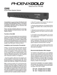
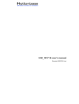
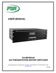
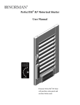
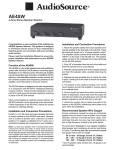
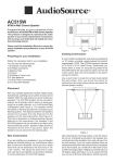
Owner's Manual
PreAmp/Tuner Two
Stereo PreAmplifier and
AM/FM Digital Tuner with Wireless
Remote Control
Power
Mute
1
Preset
11
Volume
Next
Tuning
FM/AM
Phono
C.D.
Tuner
Tape
Video 1
Video 2
Video 3
PreAmp/Tuner Two
Tuning
Model PreAmp/Tnr TWO
Stereo PreAmplifier
and Digital Tuner
Quartz PLL Digital Synthesiser
FM
1
MHz
Stereo
1
2
3
4 5
2
3
Tape
Video 1
Volume
Preset Station
Auto Memory
Bass
4
5
7
8
6
Phono
Min
AM/FM
Mono
Memory
Auto
+10
9
CD
Treble
Video 2
Remote Sensor
Tuner
Balance
Max
Min
Max
Left
Right
Min
Video 3
Max
Power
Congratulations on your new purchase, and welcome to the AudioSource family of
satisfied customers. We trust that you will continue to enjoy the value and quality of your
AudioSource PreAmp/Tuner Two. In order to make sure that you are experiencing the best
performance from your component, please take a few moments to read this manual before
you get started. Also, be sure to retain this manual should you need to refer to it in the future.
© 1996 AudioSource, Inc.
Model PreAmp/Tuner Two
Stereo PreAmplifier and AM/FM Digital Tuner
Volume
Auto
FM
AM
Remote Sensor
104.5
Stereo
Memory
MHz
KHz Tuned
Bass
1
2
3
Video 1
Tape
4
5
6
Video 2
CD
Tuning
Tuner
AM/FM
Mono
Memory
Auto
7
8
9
Video 3
Phono
Balance
15
Min
Power
Treble
+10
Max
Min
Max
Left
Right
Min
Max
Using The Controls
Power
Power : Press this button to Turn "ON" the A.C. power to the PreAmp/Tuner Two. The
Red LED indicator will remain lit when the unit is ON.
Tuning : Press the TOP END of this button to RAISE the frequency of the AM/FM tuner.
Press the BOTTOM END of this button to LOWER the frequency of the AM/FM tuner.
Tuning
Tuner : Press this button to select the Tuner as your input source. The Red LED will
indicate your selection.
Tuner
AM/FM : Press this button to select between AM and FM bands. The Red LED and
Display window will indicate your selection.
AM/FM
Mono
Memory
Auto
+10
5
Video 1
Video 2
Video 3
Mono : Press this button to receive a station in "Mono". This Button is useful for "weak"
or "hard to capture" FM stations.
Memory : Press this button when entering stations into the tuner's "Memory". When
you've found a station to store into the tuner's memory, Press this button once, and then
press the numbered buttons (#1 to #9)
Auto : Press this button to choose between "Automatic" or "Manual" tuning of radio
stations. In the "Auto" mode, the tuner will scan directly from station to station, every time
the "Tuning" button is pushed. In the "Manual" mode, the tuner will advance "up" or
"down" incrementally, every time the "Tuning" button is pushed.
+10 : Push this button "In" to access the Tuner Presets #11 to #19. Keep this button in the
"Out" position to access the Tuner Presets #1 to #9.
#1 to #9 : Push these numbered buttons to listen to "Memorized" stations, or to enter
stations into "Memory".
Video 1 : Press this button to select "Video 1" as your input source. The Red LED will
indicate your selection.
Video 2 : Press this button to select "Video 2" as your input source. The Red LED will
indicate your selection.
Video 3 : Press this button to select "Video 3" as your input source. The Red LED will
indicate your selection.
4.
Model PreAmp/Tuner Two
Stereo PreAmplifier and AM/FM Digital Tuner
Volume
Auto
FM
AM
Remote Sensor
104.5
Stereo
Memory
MHz
KHz Tuned
Bass
1
2
3
Video 1
Tape
4
5
6
Video 2
CD
Tuning
Tuner
AM/FM
Mono
Memory
Auto
7
8
9
Video 3
Phono
Balance
15
Min
Power
Treble
+10
Max
Min
Max
Left
Right
Min
Max
Using The Controls
Tape
Tape : Press this button to select "Tape" as your input source. The Red LED will indicate
your selection. Press this button simultaneously with any other "Input Source" button to
activate the "Tape Monitor" loop, allowing the signal to travel to a graphic equalizer or
outboard processor, and return to the PreAmp/Tuner Two.
CD
CD : Press this button to select "CD" as your input source. The Red LED will indicate
your selection.
Phono
Phono : Press this button to select "Phono" as your input source. The Red LED will
indicate your selection.
Bass : Turn this control to the right to increase the amount of "Bass" or "low frequencies".
Turn this control to the left to decrease the amount of "Bass" or "low frequencies".The
"12:00 Position" indicates a "Flat Response".
Bass
Treble : Turn this control to the right to increase the amount of "Treble" or "high
frequencies". Turn this control to the left to decrease the amount of "Treble" or "high
frequencies".The "12:00 Position" indicates a "Flat Response".
Treble
Balance
Balance : Turn this control to the left to increase the volume of the left channel, while
decreasing the volume of the right channel. Turn this control to the right to increase ther
volume of the right channel, while decreasing the volume of the left channel. The "12:00
position" indicates identical volume from both channels.
Volume : Turn this control to the right to increase the overall system volume. Turn this
control to the left to decrease the overall system volume. This function is also available
from the Wireless Remote Control.
Volume
5.
Using The
Wireless Remote Control
Power : Press this button to Turn "ON" the A.C. power to the PreAmp/Tuner
Two.
Mute : Press this button to "Mute" the volume of the system. All presets will
be remembered - including the previous system volume.
Power
Mute
Volume : Press the top button to raise the volume of the system. Press the
bottom button to lower the volume of the system. The motorized Volume
control's red LED and automatic movement will confirm your selection.
1
Preset
11
Volume
Next
Tuning
FM/AM
Phono
C.D.
Tuner
Tape
Video 1
Video 2
Video 3
PreAmp/Tuner Two
Tuning : Press the top button to raise the frequency of the AM/FM tuner.
Press the bottom button to lower the frequency of the AM/FM tuner.
Preset #1 & #11" : Press #1 to select a Tuner preset between #1 and #9 . Press
#11 to select a Tuner preset between #11 and #19.
Next : Used alongside the "Preset #1 & #11" buttons, this button will advance
to the "Next" Tuner preset station. For instance, either #1,2,3,4, etc., or
#11,12,13,14, etc.
FM/AM : Press this button to select between AM and FM bands on the Tuner.
Phono : Press this button to select the Phonograph as your input source.
C.D. : Press this button to select the C.D player as your input source.
Tuner : Press this button to select the Tuner as your input source.
Tape : Press this button to select the Tape Recorder as your input source.
Press this button simultaneously with any other "Input Source" button to
activate the "Tape Monitor" loop, allowing the signal to travel to a graphic
equalizer or outboard processor, and return to the PreAmp/Tuner Two.
Video 1 : Press this button to select "Video 1" as your input source.
Video 2 : Press this button to select "Video 2" as your input source.
Video 3 : Press this button to select "Video 3" as your input source.
6.
Hooking It All Up
All Components plug into the "RCA style" jacks on the rear panel of the PreAmp/Tuner Two.
L
Monitor
Record
Video 3
Video 2
Video 1
Switched
MODEL PreAmp/Tuner Two
Switched Unswitched AC 120 V 60 HZ
R
75 ohm
Phono
CD
Tape
Rec
Tape
Mon
Video 3
Rec
Video 3
Video 2
Video 1
Line
Out 2
300 ohm
GND
AM
Line
Out 1
Max Power Max Power Max Power
500 w
500 w
200 w
Power Consumption
17 w
THESE CONNECTIONS ARE PICTURED IN "SET-UP DIAGRAM #1
Audio Connections
Phono: Plug the "Line Out" jacks of your turntable into these jacks.
C.D. : Plug the "Line Out" jacks of your C.D. Player into these jacks.
Tape Mon. : Plug the "Line Out" (Play) jacks of your cassette deck into these jacks.
Tape Rec. : Plug the "Line In" (Rec.) jacks of your cassette deck into these jacks.
Video 1 : Plug the "Line Out (audio)" jacks of your "Video 1 component" (TV/Monitor) into these jacks.
Video 2 : Plug the "Line Out (audio)" jacks of your "Video 2 component" (Laserdisk) into these jacks.
Video 3 : Plug the "Line Out (audio)" jacks of your "Video 3 component" (Stereo VCR) into these jacks.
Video 3 Rec. : Plug the "Line In (audio)" jacks of your "Video 3 component" (Stereo VCR) into these jacks.
Line Out 1 : Plug these jacks into the "Line In" jacks of a stereo power amplifier.
Line Out 2 : These jacks are provided as a convenience. They may be used to send the original signal to
another amplifier, or a powered subwoofer.
Video Connections
Monitor : Plug the "Video In" jack of your T.V. Monitor into this jack.
Record : Plug the "Video In" jack of your "Video 3 component" into this jack.
Video 3 : Plug the "Video Out" jack of your "Video 3 component" into this jack.
Video 2 : Plug the "Video Out" jack of your "Video 2 component" into this jack.
Video 1 : Plug the "Video Out" jack of your "Video 1 component" into this jack.
Note: When using an outboard processor or graphic equalizer, follow the additional connections in
"Set-up Diagram #2". All other connections are identical to "Set-up diagram #1".
THESE CONNECTIONS ARE PICTURED IN "SET-UP DIAGRAM #2
Audio Connections
1. Tape Mon. : Plug the "Line Output" jacks of your outboard processor into these jacks.
2. Tape Rec. : Plug the "Line Input" jacks of your outboard processor into these jacks.
3. Plug the "Line in" jacks of your cassette deck into the "Tape 1 Rec" jacks of your outboard processor.
4. Plug the "Line Out" jacks of your cassette deck into the "Tape 1 Play" jacks of your outboard processor.
Note: In this type of system, you can listen to your cassette deck by pressing the "Tape Monitor" switch
on your outboard processor.
PreAmp/Tuner Two Specifications
Total Harmonic Distortion:----------------------------------------------------------------------------------<0.008%
Output with <0.008%:---------------------------------------------------------------------------------------------1.5 V
Frequency Response:-------------------------------------------------------------------10 Hz to 100K Hz, ±0.5 dB
Signal to Noise Ratio:------------------------------------------------------------------------------------100 dB Line
75 dB Phono
76 dB (FM/Mono)
70 dB (FM/Stereo)
60 dB (AM)
Input Sensitivity:--------------------------------------------------------------------------------------150 MV (Line)
2.5 MV (Phono)
Input Impedance:------------------------------------------------------------------------------------------------47K Ω
Alternate Channel Selectivity (FM) :---------------------------------------------------------------------------65 dB
Image Rejection (FM):--------------------------------------------------------------------------------------------70 dB
Capture Ratio (FM):------------------------------------------------------------------------------------------------1 dB
T.H.D.(FM):-------------------------------------------------------------------------------------------------Mono 0.2%
Stereo 0.4%
Image Rejection (AM) at 1000 kHz:----------------------------------------------------------------------------40 dB
IF Rejection (AM) at 1000 kHz:---------------------------------------------------------------------------------60 dB
Inputs:---------------------------------------------------------------------------------------------------------------Phono
CD
Tape
Video 1
Video 2
Video 3
Outputs:-----------------------------------------------------------------------------------------------Line Out 1 (L,R)
Line Out 2 (L,R)
Tape Rec.(Audio)
Video 3 Rec.(Audio)
Video 3 Rec.(Video)
Monitor Out (Video)
Dimensions: ...............................................................................................2 3/4" (H) x 16 1/2" (W) x 12" (D)
Weight:......................................................................................................................................................11 Lbs.
Designs and Specifications subject to change without notice
9300 North Decatur
Portland, OR 97203
(503) 286-9300 FAX(503) 978-3302
Printed in Taiwan
9.
Model PreAmp/Tuner Two
Stereo PreAmplifier and AM/FM Digital Tuner
Volume
Auto
FM
AM
Remote Sensor
104.5
Stereo
Memory
MHz
KHz Tuned
Bass
1
2
3
Video 1
Tape
4
5
6
Video 2
CD
Tuning
Tuner
AM/FM
Mono
Memory
Auto
7
8
9
Video 3
Phono
Balance
15
Min
Power
Treble
+10
Max
Min
Max
Left
Right
Min
Max
A Few Words About Your New PreAmp/Tuner Two
We at AudioSource would like to thank you for purchasing the PreAmp/Tuner Two. You can take pride
in owning this quality crafted unit; we take pride in having built it. We've combined the most useful features
of a Stereo PreAmplifier and AM/FM Digital Tuner into a single low profile unit, that will become the control
center for your Audio/Video system. You can connect a broad array of components to the PreAmp/Tuner
Two, and make your input selections from the front panel buttons, or the Wireless Remote Control.
The PreAmplifier section features versatile switching and dubbing capabilities, since we've included
Audio and Video jacks for the 3 Video sources. A Video Output jack for the TV Monitor is also provided.
Two sets of Master Line Outputs allow for direct Subwoofer connection, or multiple amplifiers within the
system. Three sets of A.C. power inputs permit direct connection of system components.
The Tuner section features 18 random station presets, with precise control over all parameters. Quartz
Digital Phase Lock Loop tuning assures pinpoint accuracy and absolute signal clarity. The Auto-Scanning
function switches to Manual tuning, and the 18 station presets can be accessed from the remote control. The
large Digital Display accurately shows all necessary parameters, such as Frequency, Signal Strength, Stereo
or Mono, Auto or Manual tuning mode, and Memory position.
All AudioSource electronic components carry a full Two-Year warranty. Please read your warranty. It
is valuable to you as well as any subsequent owner during the term of the warranty. The transferability of
the warranty is an unusual feature, and that is why we claim we warrant the product, not just the purchaser.
We have tried to supply as much information as possible, but if you need further assistance, please call our
Toll-Free customer service telephone line at 1-800-HELP-115.
3.
Hooking It All Up
Set-up Diagram #1
L
L
L
GND
R
R
PHONO
Line
Out
R
C.D. PLAYER
Line
Out
L
Monitor
Record
Video 3
Line
In
Video 2
CASSETTE DECK
Line
Out
Switched
Video 1
MODEL PreAmp/Tuner Two
Switched Unswitched AC 120 V 60 HZ
R
75 ohm
Phono
Tape
Rec
CD
Tape
Mon
Video 3
Rec
Video 3
Video 2
Video 1
Line
Out 2
300 ohm
GND
AM
Max Power Max Power Max Power
500 w
500 w
200 w
Line
Out 1
L
Video In
Power Consumption
17 w
L
Video Out
Video Out
R
VIDEO 2
‘LASERDISK PLAYER”
R
VIDEO 1
T.V. / Monitor
Variable
Line Out
Line
Out
SPEAKERS
R
L
LEFT
Line
In
L
Video In
R
Video Out
RIGHT
VIDEO 3
“STEREO VCR”
(Play + Record)
Line
Out
LINE IN
POWER AMPLIFIER
Set-up Diagram #2
TAPE 1
TAPE 2
LINE
L
L
R
PLAY
REC
PLAY
REC
INPUT
R
GRAPHIC
EQUALIZER
OUTPUT
L
Monitor
Record
Video 3
Line
In
Video 2
Video 1
CASSETTE DECK
Line
Out
Switched
MODEL PreAmp/Tuner Two
Switched Unswitched AC 120 V 60 HZ
R
75 ohm
Phono
CD
Tape
Rec
Tape
Mon
Video 3
Rec
Video 3
Video 2
Video 1
Line
Out 2
300 ohm
GND
AM
Line
Out 1
Note: All other connections are identical to "Set-up Diagram #1"
8.
Max Power Max Power Max Power
500 w
500 w
200 w
Power Consumption
17 w
Using the Antennas
FM "T" Type Antenna - If the PreAmp/Tuner two is to be used in a strong FM signal area, a "T" type antenna (dipole)
may provide adequate reception. To connect this antenna, attach its leads to the 300 Ohm terminals, fully extend the
upper sections of the "T", and position them for greatest sensitivity (maximum indication of the "Tuned" indicators
when tuned to a broadcast station). In weak signal areas, a roof-top FM antenna will be required. A 3-element antenna
is generally sufficient for medium distances and an antenna with 5 or more elements may be required for long distances
and fringe areas. Two types of outdoor antenna cables are available: 300 Ohm balanced antennas and 75 Ohm
unbalanced antennas. 300 Ohm antennas use the same flat twin lead used by most TV antennas. 75 Ohm antennas use
a coaxial cable: these antennas are recommended for use in high interference areas such as adjacent to a road where
ignition noise may be present. When installing a roof-top antenna, check that it is pointing in the direction from which
most stations are received. Do not connect antenna leads to both the 75 and 300 Ohm inputs at the same time.
Use only the terminals corresponding to the antenna cable being used.
AM Loop Antenna - In an area where signals are strong, near to the broadcast stations, the AM Loop antenna provided
on the rear panel may be adequate. This antenna is effective in all areas except those where the signal strength is very
low, or in buildings made from reinforced concrete. Position this antenna so that as many "Tuned" indicators as
possible are lighted when tuned to an AM broadcast.
Outdoor Antenna - If you have difficulty in receiving clear AM broadcasts usng the Loop antenna, connect an
external antenna to the AM terminals. Set this antenna outdoors, as high as possible. Do not disconnect the provided
AM Loop antenna.
Outdoor Antenna Grounding - If an outside antenna is to be used with the PreAmp/Tuner Two, be sure that the
antenna system is grounded so as to provide some protection against voltage surges and built up static charges. Section
810 of the National Electrical Code, ANSI/NFPA No. 70-1984, provides information concerning supporting structure,
grounding of the lead in wires to an antenna discharge unit, size of grounding conductors, location of antenna discharge
unit, connections to grounding electrodes, and requirements for the grounding electrode. See figure 1.
Antenna
Lead In
Wire
Figure 1
Antenna
Discharge Unit
(NEC Section 810-20)
Electric
Service
Equipment
Grounding Conductors
(NEC Section 810-21)
Ground
Clamps
Power Service
Grounding
Electrode System
(NEC Art 250, Part H)
2.