1
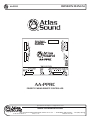
OWNER'S MANUAL
AA-PPRC
AA-PPRC
PRIORITY PAGING REMOTE CONTROLLER
Specifications are subject to change without notice
www.AtlasSound.com
1601 JACK MCKAY BOULEVARD ENNIS, TEXAS 75119 U.S.A. •
© 2007 ATLAS SOUND LP
Printed in U.S.A.
TELEPHONE: (800) 876-3333 • FAX: (800) 765-3435
ATS002915 RevA 9/07
1
OWNER'S MANUAL
AA-PPRC
ATLAS SOUND AA-PPRC
PRIORITY PAGING REMOTE CONTROLLER
TABLE OF CONTENTS
1.0 Important Safety Instructions .................................................................. 3
2.0 Introduction ............................................................................................. 4
3.0 Connection and Adjustment Identification .............................................. 5
4.0 Specifications ......................................................................................... 8
LIMITED WARRANTY
All products manufactured by Atlas Sound are warranted to the original dealer/installer, industrial or commercial purchaser
to be free from defects in material and workmanship and to be in compliance with our published specifications, if any.
This warranty shall extend from the date of purchase for a period of three years on all Atlas Sound products, including
SOUNDOLIER brand, and ATLAS SOUND brand products except as follows: one year on electronics and control systems;
one year on replacement parts; and one year on Musician Series stands and related accessories. Additionally, fuses and
lamps carry no warranty. Atlas Sound will solely at its discretion, replace at no charge or repair free of charge defective
parts or products when the product has been applied and used in accordance with our published operation and installation
instructions. We will not be responsible for defects caused by improper storage, misuse (including failure to provide reasonable
and necessary maintenance), accident, abnormal atmospheres, water immersion, lightning discharge, or malfunctions when
products have been modified or operated in excess of rated power, altered, serviced or installed in other than a workman like
manner. The original sales invoice should be retained as evidence of purchase under the terms of this warranty. All warranty
returns must comply with our returns policy set forth below. When products returned to Atlas Sound do not qualify for repair or
replacement under our warranty, repairs may be performed at prevailing costs for material and labor unless there is included
with the returned product(s) a written request for an estimate of repair costs before any nonwarranty work is performed. In the
event of replacement or upon completion of repairs, return shipment will be made with the transportation charges collect.
EXCEPT TO THE EXTENT THAT APPLICABLE LAW PREVENTS THE LIMITATION OF CONSEQUENTIAL DAMAGES
FOR PERSONAL INJURY, ATLAS SOUND SHALL NOT BE LIABLE IN TORT OR CONTRACT FOR ANY DIRECT,
CONSEQUENTIAL OR INCIDENTAL LOSS OR DAMAGE ARISING OUT OF THE INSTALLATION, USE OR INABILITY
TO USE THE PRODUCTS. THE ABOVE WARRANTY IS IN LIEU OF ALL OTHER WARRANTIES INCLUDING BUT NOT
LIMITED TO WARRANTIES OF MERCHANTABILITY AND FITNESS FOR A PARTICULAR PURPOSE.
Atlas Sound does not assume, or does it authorize any other person to assume or extend on its behalf, any other warranty,
obligation, or liability. This warranty gives you specific legal rights and you may have other rights which vary from state to state.
SERVICE
Should your AA-PPRC amplifier require service, please contact the
Atlas Sound warranty department at 1-877-689-8055, ext. 277 to obtain an RA number.
Atlas Sound Tech Support can be reached at 1-800-876-3333.
Visit our website at www.AtlasSound.com to see other Atlas products.
Specifications are subject to change without notice
www.AtlasSound.com
1601 JACK MCKAY BOULEVARD ENNIS, TEXAS 75119 U.S.A. •
© 2007 ATLAS SOUND LP
Printed in U.S.A.
TELEPHONE: (800) 876-3333 • FAX: (800) 765-3435
ATS002915 RevA 9/07
2
OWNER'S MANUAL
AA-PPRC
1.0 IMPORTANT SAFETY INSTRUCTIONS
The lightning flash with arrowhead symbol within an
equilateral triangle, is intended to alert the user to the
presence of uninsulated “dangerous voltage “ within the
product’s enclosure that may be of sufficient magnitude
to constitute a risk of electric shock to persons.
�������
�����������������������
�����������
���������
W
eered
�
������������������������������
���������������
The exclamation point within an equilateral triangle is
intended to alert the user to the presence of important
operating and maintenance (servicing) instructions in the
literature accompanying the product.
�������
��������������������������������������������
��������������������������������������������������
1.
2.
3.
4.
5.
6.
7.
8.
9.
10.
11.
12.
13.
14.
15.
16.
17.
Read these instructions.
Keep these instructions.
Heed all warnings.
Follow all instructions.
Do not use this apparatus near water.
Clean only with dry cloth.
Do not block any ventilation openings. Install in accordance with the manufacturer’s instructions.
Do not install near any heat sources such as radiators, heat registers, stoves, or other apparatus (inlcuding
amplifiers) that produce heat.
Do not defeat the safety purpose of the polarized or grounding-type plug. A polarized plug has two blades with one
wider than the other. A grounding type plug has two blades and a third grounding prong. The wide blade or the
third prong are provided for your safety. If the provided plug does not fit into your outlet, consult an electrician for
replacement of the obsolete outlet.
Protect the power cord from being walked on or pinched particularly at plugs, convenience receptacles, and the
point where they exit from the apparatus.
Only use attachments/accessories specified by the manufacturer.
Use only with the cart, stand, tripod, bracket, or table specified by the manufacturer, or sold with the apparatus.
When a cart is used use caution when moving the cart/apparatus combination to avoid injury from tip-over.
Unplug this apparatus during lightning storms or when unused for long periods of time.
Refer all servicing to qualified service personnel. Servicing is required when the apparatus has been damaged
in any way, such as power-supply cord or plug is damaged, liquid has been spilled or objects have fallen into the
apparatus, the apparatus has been exposed to rain or moisture, does not operate normally, or has been dropped.
WARNING: To reduce the risk of fire or electric shock, this apparatus should not be exposed to rain or moisture and
objects filled with liquids, such as vases, should not be placed on this apparatus.
To completely disconnect this equipment from the mains, disconnect the power supply cord plug from the receptacle.
The mains plug of the power supply cord shall remain readily operable.
CAUTION
•
•
•
•
WHEN INSTALLING THE PRODUCT
Plugging in or unplugging the power cord with wet hands may result in electric shock.
Never move the unit with the power cord plugged into the wall, as damage to the power cord may result.
When unplugging the cord from the wall, grasp the plug, NOT the cord.
Never install this product in humid or dusty locations, nor in direct sunlight, near sources of heat, or in areas
where sooty smoke or steam are present. Fire and electric shock may result.
Keep all sides of the unit at least 31⁄2" away from objects that may obstruct air flow to prevent the unit's internal
temperature rise.
Specifications are subject to change without notice
www.AtlasSound.com
1601 JACK MCKAY BOULEVARD ENNIS, TEXAS 75119 U.S.A. •
© 2007 ATLAS SOUND LP
Printed in U.S.A.
TELEPHONE: (800) 876-3333 • FAX: (800) 765-3435
ATS002915 RevA 9/07
3
OWNER'S MANUAL
AA-PPRC
WARNING
•
•
•
•
•
•
•
•
•
•
•
WHEN THE DEVICE IS IN USE
To prevent electric shock, do not remove the product cover as there are high voltage components inside. Refer all
servicing to Atlas Sound.
Should any of the following irregularities occur during use, immediately switch off the power,
disconnect the power cord from the AC outlet and contact Atlas Sound. Do not to attempt to continue operation with the
product as this may cause fire or electric shock:
•
Smoke or strange smell coming from the unit.
•
If the product falls or the case is damaged.
•
If water or any metallic objects falls into the product.
•
If the power supply cord is damaged in any way.
•
If the unit is malfunctioning.
Do not insert or drop metallic objects or flammable materials into the ventilation holes of the product's cover, as this
may result in electric shock or fire.
Do not place any containers with liquid or metallic objects on the top of the product. If any liquid spills into the unit, fire
or electric shock may result.
Never operate this product or touch the power supply cord during an electrical storm, electric shock may result.
Never exceed the wattage on the product when connecting equipment. Fire and/or property damage may result.
Operate the product only with the voltage specified on the unit. Fire and/or electric shock may result if a higher
voltage is used.
Do not modify, kink, or cut the power cord. Do not place the power cord in close proximity to heaters and do not place
heavy objects on the power cord, including the product itself, doing so may result in fire or electrical shock.
Replace the protective cover over the speaker terminals after installation. Do not touch the 70V speaker terminals as
electric shock may result.
Ensure that the safety ground terminal is connected to a proper ground. Never connect the ground to a gas pipe as a
catastrophic disaster may result.
Be sure the installation of the product is stable, avoid slanted surfaces as the product may fall and cause injury or
property damage.
2.0 INTRODUCTION
The Atlas Sound Priority Pager Relay Controller is a two input by two output speaker level relay switcher. The AA-PPRC
is designed to be placed between an amplifier output and the speaker load. It can be used with 70V or low impedance
systems. Each channel can handle up to 350 W @ 70V. Placement of the relay controller is not critical because the
systems switching can be triggered from a variety of sources. Both High Level and Line Level signals can trigger the
relay control circuit as well as a wide range of DC voltages. Contact closer terminals have also been incorporated for your
convenience. Relay release can also be adjusted allowing for proper paging override tuning. The AA-PPRC can be used in
variety of installs such as board room applications where an audio presentation system needs to be muted so the page can
be heard. The presentation system will resume when the page has completed. It is also ideal for zone paging management
for new or existing systems.
FEATURES
•
•
•
•
•
•
•
•
•
•
•
•
•
Speaker Line Remote Switcher
2 Channel
350 W @ 70V per channel
Wiring configuration for connecting or disconnecting a speaker load.
Audio High Level Trigger sense with threshold adjust
Audio Line Level Trigger sense with threshold adjust
DC Trigger
Contact Closure Trigger
Relay Trigger threshold adjust
12V DC UL power supply
Phoenix type I/O connectors
Metal housing
Compact H 1.5" x W 4" x L 4.5"
Specifications are subject to change without notice
www.AtlasSound.com
1601 JACK MCKAY BOULEVARD ENNIS, TEXAS 75119 U.S.A. •
© 2007 ATLAS SOUND LP
Printed in U.S.A.
TELEPHONE: (800) 876-3333 • FAX: (800) 765-3435
ATS002915 RevA 9/07
4
OWNER'S MANUAL
AA-PPRC
3.0 CONNECTION AND ADJUSTMENT IDENTIFICATION
1
12
2
11
10
3
4
5
6
7
8
9
1.
Amplifier Input - Normally Closed Relay Contacts (NC)
Connect an amplifier power output to this input if you need the amplifier load to be disconnected when the trigger
circuit is activated. Note: “NC” stands for Normally Closed relay contacts, thus meaning it WILL pass signal thru to the
relay output contacts without power or circuit activation. Two amplifiers channels can be switch simultaneously but is
not required to use both inputs for operation.
2.
Amplifier Input - Normally Open Relay Contacts (NO)
Connect an amplifier power output to this input if you need the amplifier load to be connected when the trigger circuit
is activated. Note: “NO” stands for Normally Open relay contacts, thus meaning it will NOT pass signal thru to the relay
output contacts without power or circuit activation. Two amplifiers channels can be switch simultaneously but is not
required to use both inputs for operation.
3.
DC Trigger
This input allows the units trigger circuitry to be activated by supplying an external DC voltage to this input. The voltage
range is rated from 3V to 24V DC. Polarity does not matter.
4.
External Switch Trigger
This input allows the units trigger circuitry to activate by an external contact closure. To activate, short these two points
together.
Specifications are subject to change without notice
www.AtlasSound.com
1601 JACK MCKAY BOULEVARD ENNIS, TEXAS 75119 U.S.A. •
© 2007 ATLAS SOUND LP
Printed in U.S.A.
TELEPHONE: (800) 876-3333 • FAX: (800) 765-3435
ATS002915 RevA 9/07
5
OWNER'S MANUAL
AA-PPRC
5.
Trigger Delay Adjustment
This screw driver adjust potentiometer determines the amount of time needed to keep the circuitry activated to
complete a page. Follow the indicator arrow to adjust the time. Note: There are a few milliseconds of delay even if the
unit is set to zero. It is suggest not to set to Zero for paging application due to pauses in ones message during a page.
This will prevent annoying repeated triggering before a page is completed.
6.
Line Level Trigger Threshold Adjustment
When using the Line Level input for circuit trigger activation, you can set the threshold voltage to activate the relay
trigger. The trigger range is from 10mV to 3V AC. To adjust, turn the screw driver trim pot to the desired setting as per
the information on the cover.
7.
Line Level Trigger Input
This input allows the unit to be activated by a audio line level signal. The input can receive signals from 10mV
to 3V AC. Wire as per the information on the box. To adjust the threshold trigger point use the Line Level Trigger
potentiometer adjustment.
8.
Speaker Level Trigger Input
This input allows the unit to be activated by a audio speaker levels. The input can receive signals from 3V to 100V
AC. Wire as per the information on the box. To adjust the threshold trigger point use the Speaker Level Trigger
potentiometer adjustment. Note: This input has a high input impedance of 47 KΩ and will not load down existing
speaker systems.
9.
Speaker Level Trigger Threshold Adjustment
When using the Speaker Level input for circuit trigger activation, you can set the threshold voltage to activate the relay
trigger. The trigger range is from 3V to 45V AC. To adjust, turn the screw driver trim pot to the desired setting as per
the information on the cover.
10. Status LED
A Bi-Color Led has been incorporated to inform you when the units has power and when the trigger circuits have been
activated. RED means power is present and Green means the unit is activated.
11. Power Supply Input
The AA-PPRC was supplied with an approved UL external 12V DC supply. Plug the supply into the DC jack supplied.
12. Speaker Load
Connect these terminals to the speaker load that you are connecting or disconnecting to. Since this a two channel
unit you can use this to control two zones. You can use one channel in the “NC” and the other in the “NO” contacts if
needed. The Left and Right contacts are independent of each other as well. Note: The AA-PPRC internal contacts are
rated at 5 Amps. Please refer to the load rating chart for maximum power handling capability.
Specifications are subject to change without notice
www.AtlasSound.com
1601 JACK MCKAY BOULEVARD ENNIS, TEXAS 75119 U.S.A. •
© 2007 ATLAS SOUND LP
Printed in U.S.A.
TELEPHONE: (800) 876-3333 • FAX: (800) 765-3435
ATS002915 RevA 9/07
6
OWNER'S MANUAL
AA-PPRC
POWER HANDLING CHART
AA-PPRC LOAD RATING
5 Amps. Max Per Channel
Load
Watts
Amps
100V (20 Ω)
500 W
5 Amps.
70V (14 Ω)
350 W
5 Amps.
25V (5 Ω)
125 W
5 Amps.
8Ω
200 W
5 Amps.
4Ω
100 W
5 Amps.
2Ω
50 W
5 Amps.
INSTALLATION DIAGRAM
RIGHT + NC
RIGHT + OUT
RIGHT + NO
From Amplifier
RIGHT - NC
RIGHT - OUT
RIGHT - NO
LEFT + NC
To Speaker Load
LEFT + OUT
LEFT + NO
LEFT - NC
LEFT - OUT
LEFT - NO
RECOVER
ADJUST
CIRCUIT
1 - 30 SEC
RELAY
TRIGGER
CIRCUIT
LINE LEVEL
SENCE
CIRCUIT
CONTACT
CLOSURE
CIRCUIT
VOLTAGE
SENCE
CIRCUIT
5 - 24VDC
TRIGGER
CONTACT
CLOSURE
-
+
LINE LEVEL
20mV - 2V
SPKR LEVEL
SENCE
CIRCUIT
-
+
SPEAKER LEVEL
3V - 100V
Specifications are subject to change without notice
www.AtlasSound.com
1601 JACK MCKAY BOULEVARD ENNIS, TEXAS 75119 U.S.A. •
© 2007 ATLAS SOUND LP
Printed in U.S.A.
TELEPHONE: (800) 876-3333 • FAX: (800) 765-3435
ATS002915 RevA 9/07
7
OWNER'S MANUAL
AA-PPRC
4.0 SPECIFICATIONS
Type
Speaker Line Remote Switcher
Channels
2
Circuit Design
Relay Switching
Load Rating Watts
350 W @ 70V (See Load Chart for other Load Ratings)
Load Rating Amps
5 Amps. per channel MAX
Indicators
One Bi-color LED Red/Green
Inputs
Qty. 4 Four Position Detachable Phoenix Connectors
Maximum Input Level
100V AC
Outputs
Qty. 1 Four Position Detachable Phoenix Connector
Maximum Output Level
100V AC
Trigger Inputs
DC Trigger 3V-24V DC Auto Sense
External Switch Trigger – Contact Closure
Line Level Trigger Input – Min 10mV, Max 5V
Speaker Level Trigger Input – Min 3V, Max 100V
Threshold Adjustments
Line Level Trigger Threshold – 10mV - 3V AC
Speaker Level Trigger Threshold – 3V - 45V AC
Trigger Delay Adjustment – 500 ms - 30 sec
Frequency Response
20 Hz – 20 kHz Flat
Enclosure
Metal
Finish
Powder Coat Black with White Lettering
Mounting
Screw hole tabs
Power Requirement
115/230V 50/60 Hz External UL Rated 12V DC Supply
Power Consumption
10 mA, .3 W
Dimensions (H x W x D)
1.5” (3.81 cm) x 4” (10.16 cm) x 4.5” (11.43 cm)
Weight
Unit 1 lbs (.45 kg) Shipping 2 lbs (.9 kg)
Specifications are subject to change without notice
www.AtlasSound.com
1601 JACK MCKAY BOULEVARD ENNIS, TEXAS 75119 U.S.A. •
© 2007 ATLAS SOUND LP
Printed in U.S.A.
TELEPHONE: (800) 876-3333 • FAX: (800) 765-3435
ATS002915 RevA 9/07
8