1
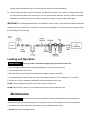
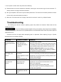
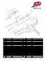
ATD-2112 1/2” TWIN HAMMER IMPACT WRENCH WARNING: Always read instructions before using power tools Always wear safety goggles Wear hearing protection Avoid prolonged exposure to vibration The instructions and warnings contained in this manual should be read and understood before operating. Keep this manual for future reference. • Technical Data Square drive………………………………………………………………………1/2” (13MM) Free speed…………………………………………………………………………7,500 RPM Max torque…………………………………………………………………………420 FT-LB Avg. air consumption…………………………………………….………………..5 CFM Operating pressure…………………………………………………………….…90 PSI Air inlet ………………………………………………………………………….…1/4” NPT Weight……………………………………………………………………………...5.70 LBS Sound pressure level……………………………………………………………. 91.6 dB(A) Sound power level………………………………………………………………..102.6 dB(A) Vibration in the handle……………………………………………….…….……..4.35 M/S2 • Important Safety Rules 1. Only use impact sockets which are specifically designed for use with an impact wrench. 2. Prolonged exposure to vibration may cause injury. 3. Read all instructions before using this tool. All operators must be fully trained in its use and aware of these safety rules. 4. DO NOT exceed the maximum working air pressure. 5. Use personal protection equipment as recommended. 6. Some dust created by power sanding, sawing, grinding, drilling, and other construction activities contains chemicals known to cause cancer, birth defects and other reproductive harm. 7. Use only compressed air at the recommended conditions. 8. If the tool appears to malfunction, remove from use immediately and arrange for service and repair. If it is not practical to remove tool from service, then shut off the air supply to the tool and write or have written a warning note and attach it to the tool. 9. If tool is to be used with a balancer or other suspension device, ensure that the tool is firmly attached to the suspension/support device. 10. When operating the tool, always keep the body and particularly the hands away from the working attachment fixed to the tool. 11. The tool is not electrically insulated. Never use the tool if there is any chance of coming into contact with live electricity. 12. Always when using the tool, adopt a firm footing and/or position and grip the tool sufficiently only to overcome any reaction forces that may result from the tool doing work. DO NOT over grip. 13. Use only correct spare parts for maintenance and repair. DO NOT improvise or make temporary repairs. Major servicing and repairs should only be carried out by a qualified person. 14. DO NOT lock, tape, wire, etc the “ON/OFF” valve in “ON” position. The throttle/lever, etc must always be free to return to the “OFF” position when released. 15. Always shut off the air supply to the tool and press the ‘ON/OFF” valve to exhaust the air from the feed hose before fitting, removing or adjusting the working attachment fitted to the tool. 16. Before using the tool, make sure that a shut off device has been fitted to the air supply line and the position is known and easily accessible so that the air supply to the tool can be shut off in an emergency. 17. Check hose and fittings regularly for wear. 18. Take care against entanglement of the moving parts of the tool with clothing, hair, ties, cleaning rags, rings, jewelry, watches, bracelets, etc. This could cause the body or parts of the body to be drawn towards and in contact with the moving parts of the tool and could be very dangerous. 19. It is expected that users will adopt safe working practices and observe all local, regional and country legal requirements when installing, using or maintaining the tool. 20. Take care that the exhaust air does not point towards any other person or material or substance that could be contaminated by oil droplets. When first lubricating the tool or if the tool exhaust has a high oil content, DO NOT allow the exhaust air to come near very hot surfaces or flames. 21. Never lay the tool down until the working attachment has stopped moving. 22. When the tool is not in use, shut off the air supply and press trigger/lever to drain the supply line. If the tools is not to be used for a period of time, first lubricate, disconnect from air supply and store in a dry average room temperature environment. 23. If the tool is passed from one user to a new or inexperienced user, make sure these instructions are passed with the tool. 24. DO NOT remove any manufacturer fitted safety devices where fitted, i.e. wheel guards, safety trigger, speed governors, etc. 25. Whenever possible, secure work piece with clamps, a vise, etc. to make it rigid so it does not move during the work operation. Keep good balance at all times. DO NOT stretch or overreach. 26. Try to match the tool to the work operation. DO NOT use a tool that is too light or heavy for the work operation. If in doubt, seek advice. 27. This tool is not suitable for underwater use or use in explosive environments. 28. Always make sure that the work area is clear to enable the work task to be performed safety. 29. Always use air hose and couplings with minimum working pressure rating at 1-1/2 times the maximum working pressure rating of the tool. Operating Instructions Air supply 1. Ensure wrench air valve (or trigger) is in the “OFF” position before connecting to the air supply. 2. You will require an air pressure of 90psi, and an air flow according to specification. 3. The air supply should be lubricated. It is strongly recommended that an air filter, regulator, lubricated is used. 4. WARNING! Ensure the air supply is clean and does not exceed 90psi while operating the wrench. Too high air pressure and unclean air will shorten the product life, and may be cause personal injury. 5. Drain the air tank daily. Water in the air line will damage the wrench. 6. Clean air inlet filter weekly. 7. Use recommended hose size and length. Line pressure should be increased to compensate for unusually long air hoses (over 25 feet). 8. Keep hose away from heat, oil and sharp edges. Check hose for wear, and make certain that all connections are secure. Lubrication An automatic in-line filter-regulator-lubricator is recommended (Fig 4) as it increases tool life and keeps the tool in sustained operation. The in-line lubricator should be regularly checked and filled with air tool oil. Proper adjustment of the in-line lubricator is performed by placing a sheet of paper next to the exhaust ports and holding the throttle open approximately 30 seconds. The lubricator is properly set when a light stain of oil collects on the paper. Excessive amounts of oil should be avoided. In the event that it becomes necessary to store the tool for an extended period of time (overnight, weekend, etc.), it should receive a generous amount of lubrication at that time. The tool should be run for approximately 30 seconds to ensure oil has been evenly distributed throughout the tool. The tool should be stored in a clean and dry environment. z It is most important that the tool be properly lubricated by keeping the air line lubricator filled and correctly adjusted. Without proper lubrication the tool will not work properly and parts will wear prematurely. z Use the proper lubricant in the air line lubricator. The lubricator should be of low air flow or changing air flow type, and should be kept filled to the correct level. Use only recommended lubricants, specially made for pneumatic applications. Substitutes may harm the rubber compounds in the tools O-rings and other rubber parts. IMPORTANT!!! If a filter/regulator/lubricator is not installed on the air system, air operated tools should be lubricated at least once a day or after 2 hours work with 2 to 6 drops of oil, depending on the work environment, directly through the male fitting in the tool housing. Loading and Operation )WARNING: Ensure you read, understand and apply safety instructions before use. 1. Only use impact sockets which are specifically designed for use with an impact wrench. 2. Connect the wrench to the air hose. 3. Place the socket over the subject nut and depress the trigger to operate the wrench. 4. To change direction, push the button at the top of the handle. Direction of “R” for reverse and “F” for forward 5. The flow of air may be regulated by adjusting flow valve at the base of the handle. DO NOT use any additional force upon the wrench in order to remove a nut. DO NOT allow wrench to free run for an extended period of time as this will shorten its life. Maintenance )WARNING: Disconnect wrench from air supply before changing accessories, servicing or performing maintenance. Replace or repair damaged parts. Use genuine parts only. Non-authorized parts may be dangerous 1. Lubricate the air wrench daily with a few drops of air tool oil dripped into the air inlet 2. DO NOT use worn or damaged sockets. 3. Loss of power or erratic action may be due to the following: a) Excessive drain on the air line. Moisture or restriction in the air pipe. Incorrect size or type of hose connectors. To remedy check the air supply and follow instructions. b) Grit or gum deposits in the wrench may also reduce performance. This tool has an air strainer (located in the area of the air inlet), remove the strainer and clean it. c) When not in use, disconnect from air supply, clean wrench and store in a safe, dry, childproof location. Troubleshooting The following form lists the common operating system with problem and solutions. Please read the form carefully and follow it. )WARNING: If any of the following symptoms appears during your operating, stop using the tool immediately, or serious personal injury could result. Only a qualified persons or an authorized service center can perform repairs or replacement of tool. Disconnect tool from air supply before attempting repair or adjustment. When replacing O-rings or Cylinder, lubricate with air tool oil before assembly. PROBLEM Tool runs at normal speed but loses under load POSSIBLE CAUSES REMEDIES Motor parts worn. ■ Cam clutch worn or sticking due to lack of lubricant. Lubricating clutch housing. ■ Check for excess clutch oil. Clutch cases need only be half full. Overfilling can cause drag on high speed clutch parts, i.e. a typical oiled/lubricated wrench requires 1⁄2 ounce of oil. ■ ■ GREASE LUBRICATED NOTE: Heat usually indicates insufficient grease in chamber. Severe operating conditions may require more frequent lubrication. Tool runs slowly. Air flows slightly from exhaust Motor parts jammed with dirt particles ■ Power regulator in closed position ■ Air flow blocked by dirt. Tools will not run. Air flows freely from exhaust One or more motor vanes stuck due to material build up. Tool will not shut off ‘O’ rings throttle valve dislodged from seat inlet valve. ■ ■ ■ Check air inlet filter for blockage. Pour air tool lubricating oil into air inlet as per instructions. ■ Operate tool in short bursts quickly reversing rotation back and forth where applicable. ■Repeat above as needed. ■ ■ Pour air tool lubricating tool into air inlet. ■ Operate tool in short bursts of forward and/or reverse rotation where applicable. ■ Tap motor housing gently with plastic mallet. ■ Disconnect supply. Free motor by rotating drive shank manually where applicable ■ ■ Replace ‘O’ ring. : Repairs should be carried out by a qualified person. ITEM# ORDERING PART# PART DESCRIPTION 1 2 3 4 5 6 7 8 9 10 11 12 13 14 15 16 17 18 19 20 21 22 PRT2112-01 PRT2112-02 PRT2112-03 PRT2112-04 PRT2112-05 PRT2112-06 PRT2112-07 PRT2112-08 PRT2112-09 PRT2112-10 PRT2112-11 PRT2112-12 PRT2112-13 PRT2112-14 PRT2112-15 PRT2112-16 PRT2112-17 PRT2112-18 PRT2112-19 PRT2112-20 PRT2112-21 PRT2112-22 WARNING LABEL OIL INLET CUP STEEL BALL ADJ. SPRING REGULATING SCREW O-RING 10.6×1.8 VALVE SLEEVE PIN VALVE STEM THROTTLE VALVE BUSHING O-RING 7.6×1.8 VALVE STEM SCREW INLET SPRING AIR INLET PLUG DUST GUARD COVER HOUSING BOLT M8×8 TRIGGER ADJ. SCREW CAP BOLT M6×10 SEAL WASHER RETAINER RING ITEM# ORDERING PART# PART DESCRIPTION 23 24 25 26 27 28 29 30 31 32 33 34 35 36 37 38 39 40 41 42 43 44 PRT2112-23 PRT2112-24 PRT2112-25 PRT2112-26 PRT2112-27 PRT2112-28 PRT2112-29 PRT2112-30 PRT2112-31 PRT2112-32 PRT2112-33 PRT2112-34 PRT2112-35 PRT2112-36 PRT2112-37 PRT2112-38 PRT2112-39 PRT2112-40 PRT2112-41 PRT2112-42 PRT2112-43 PRT2112-44 BEARING END PLATE ROTOR ROTOR BLADE PIN CYLINDER FRONT PLATE BEARING GASKET WASHER HAMMER DOG HAMMER CAGE HAMMER PIN ANVIL O-RING7.65×1.78 ANVIL COLLAR ANVIL BUSHING FIXING RING GASKET HAMMER CASE WASHER BOLT