1
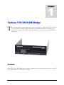
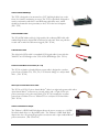
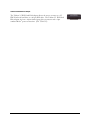
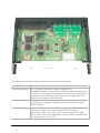
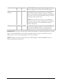
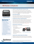
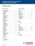
1 Volume FORENSIC COMPUTERS Tableau T35i SATA/IDE Bridge USER GUIDE FORENSIC C OMPUTERS RESEARC H AND D EVELOPMENT Forensic Write Protection Guide 2007 Forensic Computers, Inc. 110 Forensic Lane, Glen Lyn, VA 24093 Phone 540.726.9530 • Fax 540.726.9530 Apple, Mac, Macintosh, and Power Macintosh are trademarks of Apple Computer Inc., registered in the United States and other countries. Microsoft, MS-DOS, Windows, and Windows NT are either registered trademarks or trademarks of Microsoft Corporation in the United States and/or other countries. Tableau Product Images and Technical Data courtesy of Tableau, LLC © 2003-2007 Tableau, LLC Tableau is a registered trademark of Tableau, LLC. Table of Contents C H A P T E R 1 Tableau T35i SATA/IDE Bridge 4 Tableau IDE Ribbon Cable 4 8” Red SATA Flat Cable 4 Female to Female Molex® Power Cables (6” or 12”) 4 SATA 15-pin to Female Molex® Power Cable 4 Tableau 1.8 IDE Notebook Adapter 4 Tableau 2.5 IDE Notebook Adapter 5 C H A P T E R 2 TABLEAU T35I SATA/IDE BRIDGE INTRODUCTION BRIDGE OVERVIEW CONFIGURATION SWITCHES NOTES 6 7 7 10 14 1 Chapter Tableau T35i SATA/IDE Bridge T he T35i is designed to mount directly in a forensic workstation. Internally the T35i connects to the workstation through a high-performance FireWire800 connection. Externally, the T35i can be connected to SATA or IDE hard disks one at a time for write-blocked forensic acquistions. Contents In the T35i SATA/IDE bridge there are three categories of items that make up the system: the T35i SATA/IDE bridge, the cables and the adapters. 3 Tableau T35i SATA/IDE Bridge The T335 is designed to be mounted in a 5.25" half-height drive bay on the front of a forensic workstation or tower. The T335 is specifically designed to work in conjunction with SATA and IDE removable drive trays, which should be mounted in close proximity to the T335 in the host computer. (PN: T335) Tableau IDE Ribbon Cable The TC6-8 IDE ribbon cable is a high-quality, 80-conductor IDE cable with standard high-density 40-pin IDE connectors at each end. There are pull tabs at each end to make the cable more rugged. (PN: TC6-8) 8” Red SATA Flat Cable The eight inch SATA cable is a standard SATA signal cable for use with the Tableau T3u SATA Bridge or the T35e SATA/IDE Bridge. (PN: TC3-8) Female to Female Molex® Power Cables (6” or 12”) The TC2-8 or female to female Molex® power cable is designed to conduct power from a Tableau T3u, T35e, T4, or T5 forensic bridge to a subject hard drive. (PN: TC2-8) SATA 15-pin to Female Molex® Power Cable The TC5-8 or SATA 15-pin to female Molex® cable is an eight inch power cable with a 4-pin female Molex® connector on one end (white) and a 15-pin SATA style power connector at the other end (black). The TC5-8 is intended to conduct power from a Tableau T3u or a Tableau T35e to a subject SATA hard drive. (PN: TC5-8) Tableau 1.8 IDE Notebook Adapter The Tableau 1.8 IDE Hard Disk adapter allows the user to connect to a 1.8 IDE Notebook hard drive to a 40-pin IDE cable. The Tableau 1.8 IDE Hard Disk adapter also has a 50-pin male laptop drive connector and a 4-pin standard Molex® power connection. (PN: TDA5-18) 4 Tableau 2.5 IDE Notebook Adapter The Tableau 2.5 IDE Hard Disk adapter allows the user to connect to a 2.5 IDE Notebook hard drive to a 40-pin IDE cable. The Tableau 2.5 IDE Hard Disk adapter also has a 44-pin female laptop drive connector and a 4-pin standard Molex® power connection. (PN: TDA5-25) 5 2 Chapter Tableau T35i SATA/IDE Bridge T ableau's newest OEM product, the T35i, continues Tableau's heritage of industry leading innovation. The T35i offers an economical, high-performance alternative to the T345 for forensics professionals whose acquisition needs focus on IDE and SATA subject drives. The T35i is designed to mount directly in a forensic workstation. Internally the T35i connects to the workstation through a high-performance FireWire800 connection. Externally, the T35i can be connected to SATA or IDE hard disks (one at a time) for write-blocked forensic acquisitions. The T35i bundle price includes the T35i and one each of the following: TC2-8 (traditional power cable), TC5-8 (SATA style power cable), TC3-8 (SATA signal cable), TC6-8 (IDE signal cable), TDA5-25 and TDA5-18 (2.5" and 1.8" IDE notebook hard disk adapters, respectively). 6 INTRODUCTION This document provides technical information for the Tableau T35i combination Forensic SATA/IDE Bridge. The T35i combines two separate forensic bridges (IDE, and SATA) into one convenient package while providing native support for each hard disk technology. The T35i is designed to be installed permanently in the front of a forensic workstation or tower which has an open 5.25" half-height drive bay. The T35i connects to the host computer through a FireWire800 (1394B) interface. Using FireWire as the interface to the host computer allows modern operating systems to recognize that the drives themselves are hot-swappable. This, in turn, eliminates the need to turn the host computer ON and OFF each time a new hard disk is attached or removed; only the T35i needs to be power cycled. The combination of hot-swapping and the READ-ONLY forensic mode of operation make the T35i ideally suited for use in high-volume forensic applications. BRIDGE OVERVIEW The picture below is a close-up front view of the T35i. The Table below describes each of the elements visible on the front of the T35i. Front Element Power Switch/LED Description The Power switch controls power to the T35i as well as to the DC OUT connector used for powering the connected hard disk. The Power LED will be illuminated when there is power to the T35i and the power switch is in the "ON" position. 7 SATA Det LED The SATA Det LED (SATA Detect) illuminates when a hard disk attached to the SATA interface connector has been properly recognized. Only one hard disk may be connected to the T35i at a time. IDE Det LED The IDE Det LED (IDE Detect) illuminates when a hard disk attached to the IDE interface connector has been properly recognized. Only one hard disk may be connected to the T35i at a time. Host Det LED The Host Det LED (Host Detect) indicates when the connected hard disk has been recognized by the host computer. The Host Detect LED will illuminate only after the T35i has successfully identified a hard disk connected to the front of the T35i and after the host computer has "logged in" to the coresponding T35i channel using the FireWire/1394 SBP-2 protocol. Wrt Blk LED The Wrt Blk LED (Write Block) is illuminated whenever the Tableau bridge is in READ-ONLY mode. This LED provides a positive indication that the bridge may be used to capture a forensically sound image from a subject hard disk. Activity LED The Activity LED indicates that the host is performing some kind of I/O to the connected hard disk. DC OUT Connector The DC Out connector may be used to provide power from the Tableau bridge to the subject hard disk. The DC Out output is controlled by the power switch. So, using the DC Out connector guarantees that the drive will be powered ON/OFF simultaneously with the T35i bridge. Disk interface The disk interface connectors attach the subject hard disk to the T35i. Connectors (SATA and Tableau recommends the following cables: IDE) Interface Cable SATA TC3-8 IDE TC6-8 or TC6-2 The next image is a rear view of the T35i. Captions identify each internal T35i connector and the location of the configuration switches. 8 The following table describes each of the elements shown in the above picture. Internal Element 1394B (FireWire 800) DIP Switch Bank Power Description The T35i must be connected to the host computer via a FireWire800/1394B connection. This is the interface through which each of the T35i's two I/O channels will communicate with the host computer. It is acceptable to use FireWire400/1394A instead (with an appropriate cable adapter), but performance will be reduced. The T35i has one DIP switch bank with four switches. The next section in this document, Configuration Switches, describes the function of these switches in detail. Power should be provided to the T35i through the standard 4-pin "Molex"style power connector shown in the picture. The T35i requires approximately 450mA @ +5VDC for its internal operation. This figure does not include the power requirements of the hard disk connected to the DC OUT connector on the T35i. 9 IMPORTANT: Tableau strongly recommends that the T35i be on a dedicated power supply lead. Switching the T35i on/off can lead to large current/voltage surges which can interrupt the operation of other devices which share a power supply connection with the T35i. CONFIGURATION SWITCHES The following table summarizes the function of the four position DIP switch. Operation Switch Switch OFF Switch ON 1 Bridge operates in forced READ-ONLY Bridge operates in READ-WRITE mode. mode and may be used to capture forensically sound images from subject hard disks. 2 Bridge reports errors if host computer Bridge does not report write errors when in attempts to write when bridge is in READ- READ-ONLY mode. (The bridge discards ONLY mode. write data without returning an error.) 3 Bridge reports that it is WRITEBridge does not report that it is WRITEPROTECTED to the host computer when PROTECTED when in READ-ONLY in READ-ONLY mode. mode. 4 This switch is RESERVED as must remain in the OFF position for correct operation. The following table summarizes the recommended Tableau bridge configuration depending on the operating system you are using. These recommendations apply only when using the Tableau bridge in READ-ONLY mode to capture forensic images from subject hard drives (i.e., when the Write Block LED is illuminated). O/S Windows XP Windows 2000 SW2-1 OFF ON SW2-2 Comments OFF In most situations, Windows XP handles READ-ONLY bridges correctly and will work optimally when leaving switches 2 and 3 in the OFF (default) state. ON However, Tableau has seen cases where Windows XP will not allow a user to access a READ-ONLY partition. If you encounter a situation in which Windows XP reports that a volume is "write protected" and will not allow you to access the partition, then try the switch setting recommended for Windows 2000, below. Windows 2000 does not mount NTFS volumes correctly when the bridge declares that it is READ-ONLY. These settings make Windows 2000 believe the bridge is in 10 Windows ME/98se Other ON OFF OFF OFF READ-WRITE mode (even though it is not), and Windows 2000 will successfully mount NTFS volumes. Windows ME/98se may not recognize that a bridge is READ-ONLY and may attempt to write to the bridge anyway. If this happens, Windows ME/98se will generate a "blue screen" error. The recommended settings to the left eliminate the "blue screen" error. NOTE: Some forensic users prefer to see the Windows "blue screen" error if a write is attempted. Users with this preferences should use the recommended settings for Windows XP instead. Most other modern operating systems handle READONLY forensic bridges correctly, so the default OFF settings are best for users of these operating systems. IMPORTANT: As long as the Write Block LED is illuminated, the Tableau bridge will never permit writes or other modifications to the subject hard disk. Switches 2 and 3 only affect the way the bridge appears to behave from the perspective of the host computer. NOTE: Switches 2 and 3 are ignored when the Tableau bridge is in READ-WRITE mode (i.e., when the Write Block LED is off). 11 Glossary A ATA – AT Attachment is a standard interface for connecting storage devices such as hard disks and CD-ROM drives inside of personal computers. B C D DIN- the abbreviated name of the German Institute for Standardization (Deutches Institut fur Normung) and is used in the names of its standards. There are a variety of DIN connectors in existence today. The one mentioned in this text is a 5-pin DIN connector. DIP – as in DIP Switch, is an electric switch that is packaged in a group of standard dual in-line package and is designed to be used on a printed circuit board along with other electronic components and is commonly used to customize the behavior of an electronic device for specific situations. E F FireWire Symbols - a. b. The above symbols represent the IEEE1394 standard. These symbols will help you identify products that are compatible with computers and cameras that use this standard. The FireWire symbol on the left (a) is a trademark of the Apple Corporation. The i. Link symbol on the right (b) is a trademark of Sony Corporation. G H Hot swapping or hot plugging is the ability to remove and replace components of a machine, usually a computer, while it is operating. I IDE – Integrated Drive Electronics, a synonym for an ATA storage device. 12 iPOD – a brand of portable media players designed and marketed by Apple Computer. J K L M Molex® - A type of power connection used the computer industry, which has a plastic end attached to four wires: one yellow (12V), one red (5V) and two black (ground). There are female and male Molex® connectors. N O P Q R S SATA – is a traditional dish from the Malaysian state of Terenngganu, consisting of spiced fish meat wrapped in banana leaves and cooked on a grill. NO REALLY -Serial ATA, a computer bus technology primarily designed for the transfer of data from a hard disk. SCSI – Small Computer System Interface is a standard interface and command set for transferring data between devices on both internal and external computer buses. (pronounced skuzzy) T U USB – Universal Serial Bus is a serial bus standard to interface devices. It was designed for computers such as PCs and the Apple Macintosh, but its popularity has prompted it to also become commonplace on video game consoles, PDAs, cell phones and even devices such as televisions and home stereo equipment (mp3 players) and portable memory devices. V W X Y Z 13 NOTES 14