1
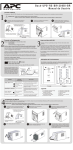
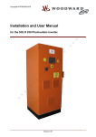
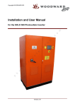
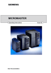
User manua l
Back-UPS ® RS B R 120 0 B I -B R
www.apc.com
Connect Battery
Problem
For your security, Back-UPS RS is provided with the battery cable disconnected. The UPS only will work after the cable is connected to the battery terminal.
1
NOTE: Small sparks may occur during battery connection.
Before connecting the battery, unplug the Back-UPS from wall outlet and also all equipement connected to the UPS. This is not a hot swap unit.
1
Press the lock that is under the UPS
and pull the bezel at the bottom.
2
Connect the battery cable to its terminal
(positive pole)
Engage the superior part of the panel in the
holes and gently push it till it locks.
3
Troubleshooting
Use the table below to solve minor Back-UPS RS installation or operation problems.
Consult APC on-line support or call APC Technical Support for assistance with problems
that cannot be resolved using the table below.
Possible Cause
Corrective Action
Back-UPS RS do not switch on.
Battery is disconnected and/or Unit is not connected
to the power source.
Connect the battery (Consult Connect the Battery section) and ensure
that is connected on ac outlet.
Connected equipment out off
power.
Circuit suit is tripped off
Reduce number of equipment connected to UPS outlets.
Retrip the circuit breaker, pushing in it.
Equipment is connected
to power
Back-UPS is heavily loaded.
Ensure the equipment switched on UPS outlets are not overloading its capacity.
Disconnect some equipment if necessary.
It is a regular operation. Reset software.
2) Press the top of the plastic panel
and twist the bottom part as shown
in the picture.
PowerChute Personal Edition software executed
UPS automatic shutdown
Some resistance to
dismount the plastic
panel will be noticed.
This is normal.
1) Press the lock that is
under the product.
Back-UPS RS discharged available power
of your battery.
Connect the Equipment
2
The Back-UPS battery wave outs were designed for computers and peripherals,
not for equipment with motor.
Switch on your Back-UPS RS
3
Place the Back-UPS to avoid:
- Direct sunlight;
- Excessive heat;
- Excessive humidity or contact with fluids.
If you want to use the management function of your Back-UPS, you shall acquire the
communication kit (part number AP9937).
Equipment does not accept sinusoidal waves
because of UPS approximation.
Press the ON/OFF switch to power the unit.
This will initiate an automatic test.
A single short beep and the green On-Line indicator confirms that Back-UPS is on
and ready to protect your equipments. The Back-UPS RS is on and ready to
provide protection.
The Back-UPS RS should charge for at least 12 hours to ensure sufficient runtime.
The unit is being charged whenever it is connected to utility power, whether the
unit is turned ON or OFF.
The supplied cable and software provide automatic file saving and shutdown of the
operating system in the case of a sustained power outage.
In case you have the AP9937 Communication Kit, install PowerChute Personal
Edition® software
If you have the communication kit, connect the interface cable to the data port at the
Back-UPS rear and the other end of the cable to the USB port of your computer.
Connect Fax / modem (ADSL) / phone
Back-UPS RS protects a single line (2-wire) fax, modem or phone from surges when it is
connected through the Back-UPS RS as shown.
To install the software, insert the CD-ROM into the drive and follow the on-screen
instructions. Refer to the software documentation to get further using instructions
and functionality.
Operation indication
Battery Back-up plus
The Back-UPS RS indicates operating status using a combination of audible
and visual indicators (leds). Refer to the “Troubleshooting”
section to get further information.
Surge Protection
Back-UPS only can run with battery power during a limited period.
UPS will be shutdown when available battery power is totally empty.
Recharge for 12 hour before continue to use them. Batteries are recharged
when the UPS is connected to power source.
These outlets are powered whenever the Back-UPS RS is switched ON. During a power outage
or other utility problems (brownouts,
over-voltages), these outlets will be
powered for a limited time by the
Back-UPS RS. Plug your computer,
Data Port Modem
Wall
Phone / FAX Outlet
monitor, and one other data-sensitive
Wall Outlet
device (external disk or tape drive)
into these outlets.
Computer
Back-UPS beep 4 times
every 30 seconds
Back-UPS is using the battery to provide
power to connected equipment.
Back-UPS is using the battery to provide power to connected equipment.
UPS is regularly working. You have to save your documents, shutdown
your equipment and the UPS. When the power supply regularly return on,
you can restart the UPS and your equipment.
The power indicator is on and
Back-UPS RS is buzzing with
continuous and short tones.
UPS is overloaded
Disconnect non-essential equipment
The overload/verify battery
indicator flashes and
Back-UPS RS buzzes with
continuous and short tones.
Unit could be not correctly connected.
Consult “Connect the Battery” section.
Batteries must be charged.
Recharge UPS, at least, 12 hours. Restarting the UPS, an automatic test will be run.
Battery has reached the end of its useful life.
If the overload/verify battery indicator still flashing and beeping a continuous and
short tons after the automatic test, batteries must be replaced.
Specifications
USB port
Warranty
Modem/Phone/Fax
Item
Status
Online – Operation is normal
(Green indicator).
Indicación
Visual / Audible
Definición
Led on.
The utility power is on security levels.
Beeping 4 times every
30 seconds.
UPS is running on battery mode and utility
power is not available at the power outlet.
Surge capacity (8 outlets)
Led on.
The power from the utility power is above or
under the range specified for product.
UPS is automatically regulating voltage
for security levels.
Overload –
(Red indicator)
ELed on, constant tone
UPS is overloaded: disconnect part
of the load connected.
Check battery
Flashing once every
second.
The battery automatic test was not successfully
completed or battery is disconnected.
Consult “troubleshooting” section.
12 Amps (including outlet UPS)
Voltage on battery
Frontal
Beeping once every second. UPS will shutdown in one minute.
Voltage Regulation –
(Yellow indicator).
Specification
Rear
Legend:
1 – Power LED
2 – Tension adjustment LED
3 – Overloaded/verify LED
4 – Power switch
5 – 220V Circuit breaker
6 – 110V Circuit breaker
7 – Power cable
8 - Data Port
9 - Modem / Phone / Fax Port
10 -Wall Outlet
115 Vac ms+/- 6%
Frequency on battery
60 Hz+/- 1Hz
Transfer time
5 ms typical
AC surge protection (Full time)
450 joules
Telephone surge protection
1 line (2 wires)
UPS automatically shuts down
if exceeds 110% of evaluated nominal
Service
Circuit breaker resettable of AC input
7A(22AV) / 15 A(115v)
NOTE: Small sparks may occur during battery connection.
Before connecting the battery, unplug the Back-UPS from wall outlet and also all equipement connected to the UPS. This is not a hot swap unit.
1
2
3
Disconnect the battery and, then, unscrew
the frontal metallic panel
2) Press the top of the plastic panel
and twist the bottom part as shown
in the picture.
Note:
Battery type
Sealed, maintenance-free lead acid
Average life
2 to 4 years, depending on number of
discharge cycles and enviromental temperature.
Usually 12 hours, maximum of 16 hours
Recharge time
Size (HxWxD)
4
Please DO NOT RETURN Back-UPS RS to the place of purchase
under any circumstances.
1. Consult the “Troubleshooting section” to eliminate common problems.
2. Verify the battery is connected according to “Connect the Battery” and that the Circuit Breaker is not
33 lb
15,0 kg
If you still have questions, please contact APC via www.apc.com/br or at one of the phone numbers
7.87x6.50x13.0 inch
20.0x16.5x33.0 cm
3. Before contacting APC, please be sure to keep at hands the date purchased, UPS model, and serial
Operating temperature
+32º to 104ºF
0º to 40ºC
Storage temperature
+5º to 113ºF
15º to 45ºC
listed below.
number (on rear part of unit).
4. If necessary, Technical Support Representative will issue a Return Material Authorization Number
(RMA#).
5. Pack the unit properly to avoid shipment damage. Never use foam beads for packaging. Damage
Some resistance to
dismount the plastic
panel will be noticed.
This is normal.
Turn the cap down and remove it.
UPS detailed specifications are available on www.apc.com/br.
tripped (see “Troubleshooting section”).
Net weight
1) Press the lock that is
under the product.
Battery must be recycled. Please delivery spent batteries
on APC reseller.
Full time
UPS for overload protection
Disconnect the central wires and the protection
fuses from battery terminals.
How to order replacement battery
New package battery can be bought from your local dealer. Hold your Back-UPS RS model
number that can be found on rear part of the equipment. Use always APC certified batteries.
When Back-UPS indicates the need of replacing battery, you should order an APC certified battery pack and proceed as following described:
1 Press the lock that is under the UPS
and pull the bezel by the bottom.
How to buy a AP9937 Communication Kit
The AP9937 Communication Kit can be purchased at any APC dealer or local dealer.
EMI/RFI filter
Replacing the battery
The standard warranty is 2 years from the date of purchase. APC’s standard procedure is to replace
the original unit with a factory reconditioned unit. Customers who must have the original unit back
due to assigned asset tags and set depreciation schedules must declare such a need at first contact
with APC Technical Support. APC will ship the replacement unit once the defective unit is received
by the repair department or cross-ship upon the provision of a valid credit card number. The
customer pays for shipping to APC, and APC pays ground freight transportation costs back to the
customer.
Remove battery package from the product and
replace it. UPS is supplying battery power to
the load connected to the Battery outlets.
6
Reconnect all cables in the inverse order of
disassembling. Engage the metal cap and
screw it again. Engage the plastic panel superior
part and press it softly on rear until it locks.
0 to 10000 feet
0 to 3000m
Operating elevation
86 – 149 Vac (115V)
170-260Vac(220V)
Input nominal voltage and
adjustment range
Output voltage and adjustment range
Nominal power
mended).
0 to 95% non-condensing
Operating relative humidity
5
sustained in transit is not covered under warranty (insuring the package for full value is recom-
115V+/-6%
1200VA / 600 W
APC Contact Information
USA/Canada
Mexico
Brazil
Worldwide
Web Site
Online Technical Support
1.800.800.4272
+52.292.0253 / 52.292.0255
+0800.555.272
+1.401.789.5735
www.apc.com/br
http://support.apc.com
990-2767 Rev5 Copyright © 2006 American Power Conversion Corp. All other trademarks are property of their respective owners.
APC, Back-UPS and PowerChute are registered trademarks of American Power Conversion Corp.