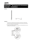
1
InfraStruXure™
Installation and Start-Up
Large Data Centers
415 and 200V Input
This manual is available in English on the enclosed CD.
About this Manual
This manual is intended for APC Field Service Engineers or APC-trained installers of an
InfraStruXure system for large data centers. It covers basic installation and start-up.
For information about installing specific components in your InfraStruXure system, see the
documentation included with each component. Before installing or operating any component, refer to
the safety instructions in the component’s manual.
The illustrations of products in this manual may vary slightly from the products in your InfraStruXure
system.
You can check for updates to this manual by clicking on the User Manuals link on the
Support page of the APC website (www.apc.com). In the list of InfraStruXure
manuals, look for the latest letter revision (A, B, etc.) of the part number on this manual.
InfraStruXure Site Planning, Installation, Start-Up
i
Contents
Safety ......................................................................1
Overview . . . . . . . . . . . . . . . . . . . . . . . . . . . . . . . . . . . . . . . . . 1
Save these instructions . . . . . . . . . . . . . . . . . . . . . . . . . . . . 1
Safety symbols used in this manual . . . . . . . . . . . . . . . . . . . 1
Cross-reference symbols used in this manual . . . . . . . . . . . . . 1
Warnings . . . . . . . . . . . . . . . . . . . . . . . . . . . . . . . . . . . . . . . . . 2
Installation/Maintenance . . . . . . . . . . . . . . . . . . . . . . . . . . 2
Maintenance performed while the PDU is
receiving input power . . . . . . . . . . . . . . . . . . . . . . . . . . . . 2
Total power off procedure . . . . . . . . . . . . . . . . . . . . . . . . . 2
Register equipment with the fire department . . . . . . . . . . . . . 2
Site Preparation........................................................3
Dimensions . . . . . . . . . . . . . . . . . . . . . . . . . . . . . . . . . . . . . . . . 3
InfraStruXure PDU . . . . . . . . . . . . . . . . . . . . . . . . . . . . . . . 3
NetShelter VX Seismic Enclosure . . . . . . . . . . . . . . . . . . . . . 3
NetShelter VX Enclosure . . . . . . . . . . . . . . . . . . . . . . . . . . . 4
Space Considerations . . . . . . . . . . . . . . . . . . . . . . . . . . . . . . . . 5
Weight Considerations . . . . . . . . . . . . . . . . . . . . . . . . . . . . . . . 6
Heat Output . . . . . . . . . . . . . . . . . . . . . . . . . . . . . . . . . . . . . . . 7
Electrical Requirements and Specifications . . . . . . . . . . . . . . . . . 8
Procedures requiring a licensed electrician . . . . . . . . . . . . . . 8
Electrical requirements . . . . . . . . . . . . . . . . . . . . . . . . . . . . 8
Basic Installation Procedure . . . . . . . . . . . . . . . . . . . . . . . . . . . . 9
Installation Procedures ...........................................11
Join Adjacent Enclosures and Bolt Enclosures to the Floor . . . . 11
Join adjacent enclosures . . . . . . . . . . . . . . . . . . . . . . . . . . 11
Bolt Enclosures to the Floor . . . . . . . . . . . . . . . . . . . . . . . 11
InfraStruXure Site Planning, Installation, Start-Up
iii
Ensure Total Power Off . . . . . . . . . . . . . . . . . . . . . . . . . . . . . . 12
Connect the Power Source to the PDU . . . . . . . . . . . . . . . . . . . 13
Access the PDU Main Input switch . . . . . . . . . . . . . . . . . . . 13
Attach conduit to the PDU for the input conductors . . . . . . . 13
Install a circuit breaker . . . . . . . . . . . . . . . . . . . . . . . . . . . 15
Route the input conductors to the main input circuit switch . 15
Torque specifications and tools required . . . . . . . . . . . . . . . 15
Connect input conductors . . . . . . . . . . . . . . . . . . . . . . . . 16
Connect User Contact Inputs and Output Relays to
the User Connection Plate . . . . . . . . . . . . . . . . . . . . . . . . . . . . 17
Overview . . . . . . . . . . . . . . . . . . . . . . . . . . . . . . . . . . . . 17
How to connect contacts to the PDU Monitoring Unit . . . . . . 18
Install Shielding Troughs, Shielding Partitions,
and Cable Ladders . . . . . . . . . . . . . . . . . . . . . . . . . . . . . . . . . . 19
Shielding Troughs and Shielding Partitions for overhead
wiring along rows . . . . . . . . . . . . . . . . . . . . . . . . . . . . . . 19
Cable Ladders for overhead wiring across rows . . . . . . . . . . 20
Install InfraStruXure Rack-Mount Devices . . . . . . . . . . . . . . . . . 21
Install the Rack Automatic Transfer Switches (ATS) . . . . . . . . 21
Install the Rack Power Distribution Units (PDU) . . . . . . . . . . 21
Install the InfraStruXure Manager and Hub (or Switch) . . . . . 21
Install the APC Environmental Monitoring Unit . . . . . . . . . . 21
Route and Attach Overhead Wiring . . . . . . . . . . . . . . . . . . . . . 22
Route and attach power cables to equipment racks . . . . . . . 22
Wiring Under the Floor (Alternative) . . . . . . . . . . . . . . . . . . . . 25
Route Data Cables to the InfraStruXure
Manager Hub (or Switch) . . . . . . . . . . . . . . . . . . . . . . . . . . . . . 27
Connect network cables to InfraStruXure components . . . . . 27
Route network cables to the InfraStruXure
Manager hub (or switch) . . . . . . . . . . . . . . . . . . . . . . . . . 28
Start-Up Procedure ................................................ 29
Safety warnings . . . . . . . . . . . . . . . . . . . . . . . . . . . . . . . 29
Ensure that all power is off . . . . . . . . . . . . . . . . . . . . . . . . 29
Apply power to the system . . . . . . . . . . . . . . . . . . . . . . . . 30
iv
InfraStruXure Site Planning, Installation, Start-Up
Configuration.........................................................33
Configure the InfraStruXure Manager . . . . . . . . . . . . . . . . . . . 33
Appendix A—System Operation .............................35
How to Apply Power to the System . . . . . . . . . . . . . . . . . . . . . 35
How to Ensure Total Power Off . . . . . . . . . . . . . . . . . . . . . . . . 36
InfraStruXure Site Planning, Installation, Start-Up
v
Safety
Overview
Save these instructions
This manual contains important instructions that must be followed during installation, operation, and
maintenance of the InfraStruXure System.
Safety symbols used in this manual
Indicates an electrical hazard, which, if not avoided, could result in injury or
death.
Indicates a hazard, which, if not avoided, could result in personal injury or
damage to product or other property.
Indicates a potential hazard which could result in damage to product or other property.
Indicates important information.
Indicates a heavy load that should not be lifted without assistance.
Indicates a standby state. When in standby, the unit is not operating, but it may still
contain hazardous voltage. It is not safe to service until the equipment is
disconnected from all sources of electrical power.
Cross-reference symbols used in this manual
Indicates that more information is available on the same subject in a different manual.
See also
Indicates that more information is available on the same subject in a different section
of this manual.
InfraStruXure Site Planning, Installation, Start-Up
1
Warnings
Installation/Maintenance
Only a certified electrician can do following:
• Connect the PDU to its power source
• Install a customer-specified, hard-wired power cable
Only a certified electrician or an APC Field Service Engineer can perform maintenance of the PDU.
When connecting the PDU to utility, a circuit breaker must be installed to protect the PDU against
short-circuit current. Determine the type of circuit breaker that you need to install:
Input Voltage
Circuit Breaker Size
200V
200A
415V
100A
Maintenance performed while the PDU is receiving input power
APC does not recommend that you perform maintenance of the PDU while it is receiving input
power. However, due to the critical nature of data center loads, this may occur. If you must perform
maintenance while the PDU is receiving input power, observe the following precautions to reduce the
risk of electric shock:
1. Never work alone.
2. Perform the maintenance only if you are a certified electrician who is trained in the hazards of
live electrical installation.
3. Know the procedure for disconnecting electricity to the PDU and the data center in case of an
emergency.
4. Wear appropriate personal protective equipment.
5. Use double-insulated tools.
6. Always follow local and site regulations when working on the PDU.
Total power off procedure
1. Set the PDU Main Input to Off.
2. Set the upstream power source circuit breaker to Off.
Register equipment with the fire department
Follow local code ordinances and register all fire code-compliant equipment with the fire department.
2
InfraStruXure Site Planning, Installation, Start-Up
Site Preparation
Dimensions
InfraStruXure PDU
Shielding Partitions
With trough: 2243mm
580mm
120mm
Shielding Trough
Without trough: 2058mm
185mm
580mm
597mm
871mm
NetShelter VX Seismic Enclosure
Base Enclosure
Shielding Partitions
580mm
2070mm
120mm
Shielding Trough
185mm
580mm
597mm
1072mm
InfraStruXure Site Planning, Installation, Start-Up
3
Site Preparation: Dimensions
NetShelter VX Enclosure
Base Enclosure
597mm
Shielding Partitions
597mm
122mm
2070mm
Shielding Trough
183mm
597mm
1071.9mm
4
InfraStruXure Site Planning, Installation, Start-Up
Space Considerations
Study the figures below to determine your space requirements for installing the InfraStruXure PDU,
Symmetra PX UPS, and XR Battery Enclosure. Consult your local and national codes for additional
requirements.
>300mm
Ceiling Clearance
300
>600mm
Rear Clearance
>1000mm
Front Clearance
InfraStruXure Site Planning, Installation, Start-Up
5
Weight Considerations
Use the “Maximum Packaged” weights to determine what methods you will use to move equipment
into your data center.
Use the “Maximum Unpacked” weights to ensure that the floor and subfloor can support the total
weight of the configuration. If you are placing equipment on a raised floor, consult the flooring
manufacturer for loading requirements before installing equipment. For assistance in planning your
configuration, call APC Customer Support in Japan at the number listed on the back cover of this
manual.
Component
6
Maximum Unpacked
Maximum Packaged
InfraStruXure PDU
550kg
591kg
NetShelter VX Seismic Enclosure (empty)
235kg
253kg
NetShelter VX Enclosure (empty)
163kg
180kg
InfraStruXure Site Planning, Installation, Start-Up
Heat Output
Consider the heat dissipation ratings of equipment to determine cooling requirements. Additional
cooling equipment may be required. Heat output of the InfraStruXure PDU is shown below.
InfraStruXure PDU
Heat Output
200V input
3496 BTU/hr (1.025kW)
415V input
3746 BTU/hr (1.098kW)
InfraStruXure Site Planning, Installation, Start-Up
7
Electrical Requirements and Specifications
Procedures requiring a licensed electrician
A licensed electrician must connect utility power. The following procedures
require a licensed electrician:
• connection of utility conductors
• installation of a 200- or 100-amp circuit breaker
• connection to the main input switch
• connection to a branch circuit
To connect utility power, see the utility connection instructions included with your
documentation.
See also
Electrical requirements
200V Input
415V Input
Service distribution breaker 1,2
200A
100A
Conductors to Main Input switch1
3W + G
3W + G
L1, L2, L3
60mm2
38mm2
G
14 mm2
8 mm2
Recommended wire sizing 2,3
8
1
Provided by customer
2
Consult national and local codes for requirements specific to your installation.
3
CV or CVT cable
InfraStruXure Site Planning, Installation, Start-Up
Basic Installation Procedure
This section provides the basic steps that you need to perform when installing InfraStruXure power
and rack components. Follow the references provided with each step for detailed instructions.
Do not begin installing your InfraStruXure system without an APC Field Service
Engineer present.
1. Unpack the components according to the unpacking instructions included on the outside of the
packaging or in the installation manual included with the component.
Make sure that all boxes and packaging are empty before discarding them.
2. Determine the correct placement of your system components by studying your APC
InfraStruXure configure-to-order (CTO) report. Move the InfraStruXure PDU and enclosures to
their final location.
If installing InfraStruXure on a raised floor, make sure that the raisedfloor structure has a kg/m2 rating that will support the full weight of the
InfraStruXure installation. See “Weight Considerations” on page 6.
3. Join adjacent NetShelter enclosures.
For instructions on joining adjacent NetShelter VX Seismic Enclosures, see the
installation manual included with your enclosures.
See also
4. Bolt enclosures to the floor.
See page 11 for detailed instructions.
5. Ensure total power off.
See page 12 for detailed instructions.
InfraStruXure Site Planning, Installation, Start-Up
9
Site Preparation: Basic Installation Procedure
6. Connect the power source to the PDU.
A licensed electrician must connect the power source.
See page 13 for detailed instructions.
7. Connect user contact inputs and output relays to the user connection plate.
See page 17 for detailed instructions.
8. Install Shielding Troughs, Shielding Partitions, and Cable Ladders.
For instructions, see the manuals included with your Shielding Troughs,
Shielding Partitions, and Cable Ladders.
See also
9. Install the Rack Automatic Transfer Switches (ATS), Rack Power Distribution Units, and other
InfraStruXure rack-mount devices.
For instructions, see the manuals included with your Rack ATS, Rack PDU, or
other InfraStruXure rack-mount device.
See also
10. Route and attach PDU power cables to each Rack ATS and/or Rack PDU.
See page 22 for detailed instructions.
11. Route and attach communication cables to the InfraStruXure Manager hub (or switch).
See page 27 for detailed instructions.
12. Start the system.
Only qualified, APC-trained personnel may perform a system start-up.
See page 29 for detailed instructions.
13. Configure the InfraStruXure Manager.
For instructions, see the manual included with your InfraStruXure Manager.
See also
10
InfraStruXure Site Planning, Installation, Start-Up
Installation Procedures
Join Adjacent Enclosures and Bolt
Enclosures to the Floor
Join adjacent enclosures
To join NetShelter VX Enclosures, see the installation manual included with your
enclosures.
See also
Bolt Enclosures to the Floor
Proper anchoring hardware must be in place before starting this procedure.
To bolt the PDU and enclosures to the floor, follow these steps for each enclosure:
1. Remove the front and rear skirts on the enclosure.
2. Insert two bolts through each plate and the holes in the plinth, using the bolt plate (included).
Screw the bolts into the pre-installed anchoring hardware in the floor.
3. Tighten the bolts to 81 n·m, using a torque wrench.
InfraStruXure Site Planning, Installation, Start-Up
11
Ensure Total Power Off
1. Set the main input switch on the PDU to OFF.
2. Open (turn OFF) the main output circuit breaker on the PDU.
3. Set the power source circuit breaker to OFF.
12
InfraStruXure Site Planning, Installation, Start-Up
Connect the Power Source to the PDU
Access the PDU Main Input switch
Open the back doors of the PDU, unlock the top, smaller door, using the provided red key. Loosen the
two captive screws holding the larger, hinged door in place, using a Phillips or standard screw driver.
Attach conduit to the PDU for the input conductors
1. Remove the rectangular input gland plate by loosening the captive screws, using a Phillips or
standard screwdriver:
– In the top of the PDU for overhead wiring
– In the bottom of the PDU for wiring under a raised floor
InfraStruXure Site Planning, Installation, Start-Up
13
Installation Procedures: Connect the Power Source to the PDU
2. Create an appropriately-sized hole in the gland plate for the
conduit.
The input gland plate has two knock-outs. Use
either as starter hole for creating a hole for your
conduit. Use a knock-out punch to create a
larger hole.
3. Re-attach the gland plate.
4. Install a lock-nut and bushing to the conduit.
5. Thread the conduit through the hole.
14
InfraStruXure Site Planning, Installation, Start-Up
Installation Procedures: Connect the Power Source to the PDU
Install a circuit breaker
Make sure the cables used for power input are sufficiently protected by a
appropriately-rated circuit breaker. See “Electrical Requirements and
Specifications” on page 8.
Route the input conductors to the main input circuit switch
1. Route the input conductors to the main input circuit switch of the PDU, as follows:
– For overhead wiring, run the input conductors directly to the main input switch.
– For wiring under a raised floor, run the input conductors through
the wireway (,) within the PDU to the main input switch.
,
Torque specifications and tools required
Before connecting to the terminals, verify the torque specifications below by checking the
specifications on the main input switch.
Terminal
Torque
Tools
200V input: 8–13N·m
415V input: 5–7 N·m
6-mm Allen wrench
#3 Plus Driver
14N·m
3/16-mm Allen wrench
L1, L2, L3
PE
InfraStruXure Site Planning, Installation, Start-Up
15
Installation Procedures: Connect the Power Source to the PDU
Connect input conductors
A licensed electrician must connect input conductors to the PDU!
At the main input switch, connect the input
wiring according to the labels on the switch and
the illustration on this page. See the table,
“Torque specifications and tools required” on
page 15 for information about connecting to
each terminal.
Connect the conductors to the
terminals according to the labels
on the terminals. Use copper
conductors only.
Note: This image is of a PDU with 200V input.
16
InfraStruXure Site Planning, Installation, Start-Up
Connect User Contact Inputs and Output
Relays to the User Connection Plate
Overview
4
Contact Outputs
ATS 1
2
3
Contact Inputs
ATS 2
1
ATS 0
USER INTERFACE
© 2001 APC
MADE IN USA
ATS EN
Make contact closure connections (NO
or NC) at the user connection plate to
monitor dry contacts. You can make
eight connections—four contact inputs
and four output relays.
– +
EPO 24V EPO
AC/DC Contact
The figure at the right shows the location
of the user connection plate on the roof
of the PDU enclosure.
You can make connections from inside
the enclosure, or you can remove the
user connection plate and make your
connections.
Remove the plate using a Phillips or
standard screw driver to loosen the two
captive screws. Use the knockout in the
plate to route cables to and from the user
connections on the plate. If you remove
the plate, make sure that you do not
disturb the existing connections.
Output relay specifications
Nominal switching capacity:
Maximum switching power:
Maximum switching voltage:
Maximum switching current:
Maximum carrying current:
Surge ratings:
1A at 30VDC
30W
60VDC
2ADC
2ADC
2kV per Bellcore TA-NWT-001089
1.5kV per FCC part 68
InfraStruXure Site Planning, Installation, Start-Up
17
Installation Procedures: Connect User Contact Inputs and Output Relays to the User Connection Plate
How to connect contacts to the PDU Monitoring Unit
To connect and monitor your contacts:
1. Choose the numbers of the contacts to which you will connect.
2. From the PDU display interface:
a. Press the ESC or ENTER key to go to the top-level menu screen.
b. Select Contacts on the top-level menu screen and press the ENTER key.
c. Press the ENTER key to select the number of the contact you are connecting. The continue
arrow will appear next to the contact number.
d. Press the Up or Down arrow key to select the appropriate contact number and press the ENTER
key.
e. Press the Down arrow key to enter a unique Name for the contact and to configure the
Normal state of the contact (Open or Closed). The default Normal state is Open. Press the
ENTER key to select the item you wish to configure.
You will be prompted for your password to configure these items.
3. Connect contact wires (300V-rated cabling required) to the terminal block on the user
connection plate. You will need a 2.5-mm standard screwdriver.
4. Run the wires from the terminal block out the roof or under the floor of the PDU to your
contact’s location.
Ensure that wires are properly retained and away from high voltage lines
and breakers.
18
InfraStruXure Site Planning, Installation, Start-Up
Install Shielding Troughs, Shielding Partitions,
and Cable Ladders
Shielding Troughs and Shielding Partitions for overhead wiring along rows
If you ordered APC Shielding Troughs, Shielding Partitions, and Cable Ladders to route overhead
wiring for your system, assemble the Shielding Troughs and the Shielding Partitions along the rows
of enclosures and assemble the Cable Ladders between rows.
See also
For information on grounding the Shielding Troughs and Shielding Partitions, see the
instruction sheet (990-1393B) included with the Shielding Troughs and Shielding
Partitions.
Shielding Troughs. There are two types of Shielding Troughs:
• The PDU Shielding Trough, 610mm in length, is not adjustable. The trough attaches to the top
of the PDU and accommodates power cables as they exit from the roof of the PDU.
• The NetShelter Shielding Trough is 610mm in length and is not adjustable. Each Shielding
Trough has an opening in each side through which you route data cables to the Shielding
Partitions.
Shielding Trough accessories. APC offers the following accessories for Shielding troughs:
• Shielding Trough Covers for both 600-mm wide (AR8174BLK) and 750-mm wide
(AR8175BLK) enclosures. Contact APC for more information.
• Shielding Trough End Caps (AR8167BLK) to place on the ends of Shielding Troughs at the
end of rows. Contact APC for more information.
InfraStruXure Site Planning, Installation, Start-Up
19
Installation Procedures: Install Shielding Troughs, Shielding Partitions, and Cable Ladders
Shielding Partitions. There are two types of Shielding Partitions, each of which forms a side wall
of a trough for data cables. You can customize the width of the trough for each row of your system —
wider for rows carrying many data cables, narrower for rows carrying fewer.
• As the back wall, use a Shielding Partition that
contains an opening for routing data cables.
• As the front wall, use a solid Shielding Partition to
hide data cables for a clean appearance.
Cable Ladders for overhead wiring across rows
After installing the Shielding Troughs and Shielding Partitions, install the Cable Ladders between
rows of enclosures. You can also run Cable Ladders across Shielding Troughs in the same row, using
the hardware provided in the ladder kit.
For more information on installing the Cable Ladders, see the instruction sheet included
with the cable ladders (990-1576).
See also
Use wide Cable Ladders (305 mm) where many power cables or data cables will run between rows;
use narrow Cable Ladders (152 mm) where few power cables or data cables will run between rows.
The Cable Ladders are 2946 millimeters long. You can adjust the length of the Cable Ladders in the
following ways:
• Cut the ends with a hacksaw to shorten them.
• Insert the connectors only partially into the side rails to extend them.
Do not change the spacing between rows or the length and position of the Cable
Ladders from the layout you planned with your APC representative when you placed
your order. For overhead wiring, each PDU power cable is provided at a pre-determined
length. Changes to the physical configuration of your system could cause some PDU
power cables to be too short or too long.
20
InfraStruXure Site Planning, Installation, Start-Up
Install InfraStruXure Rack-Mount Devices
Install the Rack Automatic Transfer Switches (ATS)
Install a Rack ATS in the top of each enclosure for overhead wiring, and in the bottom of each
enclosure for wiring under the floor.
See the installation instructions in the manual included with your Rack ATS.
See also
The Rack ATS is an optional component, and not all InfraStruXure systems will include it.
Install the Rack Power Distribution Units (PDU)
Install Rack PDUs in the rear of the NetShelter VX enclosure, in the channel directly behind the rear
vertical mounting rails. For overhead wiring, make sure that the power cord is pointing toward the
roof of the enclosure. For wiring under the floor, make sure that the power cord is pointing toward the
floor.
See the installation instructions in the manual included with your Rack PDU.
See also
The Rack PDUs is an optional component, and not all InfraStruXure systems will include it.
Install the InfraStruXure Manager and Hub (or Switch)
Install the InfraStruXure Manager in the enclosure closest to the PDU. The CAT5 data cables
included with your configuration are of varying lengths, based on the distance components will be
installed from the PDU.
See the installation instructions in the manual included with your InfraStruXure
Manager.
See also
Install the APC Environmental Monitoring Unit
Install the Environmental Monitoring Unit according to the installation instructions included with the
device. The Environmental Monitoring Unit is an optional component, and not all InfraStruXure
systems will include it.
InfraStruXure Site Planning, Installation, Start-Up
21
Route and Attach Overhead Wiring
Route and attach power cables to equipment racks
If you ordered overhead wiring, connect the prewired power cables of the PDU as follows:
1. Install the Shielding Troughs, Shielding Partitions, and Cable Ladders so that you can route
power cables from the PDU to the NetShelter VX Enclosures.
For installation instructions, see the manual included with your Shielding
Troughs, Shielding Partitions, and Cable Ladders.
See also
2. Find the numbers that indicate the enclosure to which each power cable will supply power.
These numbers appear on the roof of the PDU where the power cables exit, and on the ends of
each power cable.
The enclosures are not numbered. Consult your APC InfraStruXure ConfigureTo-Order (CTO) report to determine the enclosure associated with each power
cable.
3. Beginning with the power cables for the enclosures farthest from the PDU, run each power
cable within the Shielding Trough along the row and, if necessary, across one or more Cable
Ladders to the enclosure to which it will provide power.
Ensure that the connector at the end of each power cable always lies on top of
any longer power cables in the Shielding Trough.
4. Connect the appropriate power cable to APC power management equipment in the enclosure in
one of the four following ways:
– For single-feed devices without redundancy: attach a power cable directly to a Rack PDU
installed in a NetShelter VX Enclosure.
22
InfraStruXure Site Planning, Installation, Start-Up
Installation Procedures: Route and Attach Overhead Wiring
– For dual-feed devices within a redundant system: attach a power cable from each PDU into
two different Rack PDUs in the NetShelter VX Enclosure.
– For single-feed devices within a redundant system with an Automatic Transfer Switch:
connect a power cable to the Automatic Transfer Switch (A and B feeds) and connect the
Automatic Transfer Switch power cord to a Rack PDU in the NetShelter VX Enclosure.
– For dual-feed devices in a redundant system with an Automatic Transfer Switch: connect a
power cable from each PDU to the Automatic Transfer Switch’s A and B feeds, and another
power cable from one PDU to a Rack PDU, and the Automatic Transfer Switch’s power cord
to a second Rack PDU in the NetShelter VX Enclosure.
Lay the cables neatly in the Shielding Trough to minimize cable build-up.
InfraStruXure Site Planning, Installation, Start-Up
23
Installation Procedures: Route and Attach Overhead Wiring
5. From each NetShelter VX Enclosure, run the power cable of the appropriate APC power
management device out the roof of the enclosure, through the notch in the rear side of the
Shielding Trough, to the connector of the appropriate power cable from the PDU. Plug the two
connectors together, and twist them clockwise to lock.
24
InfraStruXure Site Planning, Installation, Start-Up
Wiring Under the Floor (Alternative)
A licensed electrician must route and connect the power cables for wiring under the
floor.
Make sure all wire connections and circuit breaker connections are properly
torqued.
If you are routing power cables under a raised floor to the enclosures, you must provide the
appropriate power cables and equipment for installation, and a licensed electrician must route and
connect the power cables to the PDU circuit breakers. To wire each power cable to an enclosure:
1. Push out a knock-out filler in the floor of the PDU to create an opening for the cable.
2. From the Rack PDU or Rack ATS in each enclosure, thread the appropriate power cable (for
your application) from the enclosure to the PDU.
3. At the PDU, route the cable through the opening you created in step 1 and then up through the
wireway (,) at either side of the PDU. This will allow you to connect the cable to the upper
circuit breaker panel.
,
InfraStruXure Site Planning, Installation, Start-Up
25
Installation Procedures: Wiring Under the Floor (Alternative)
4. At the circuit breaker panel,
cut the wires to the proper
length, and connect the
power cable’s individual
wires:
a. If you have branch
current monitoring
installed, route each
phase conductor through
a current sensor. If it is a
multi-circuit cable, route
the L1, L2, and L3 wires
through separate current
sensors.
b. Connect the L1, L2, and
L3 wires to the circuit
breaker(s). The
illustration at right
shows a single-circuit
cable connecting to a
single-pole breaker;
however, you can also
connect a multi-circuit
cable to a four-pole
breaker.
c. Connect the neutral wire
to the closest open termination point on the Neutral Bar.
d. Connect the PE wire to the closest open termination point on the PE Bar.
5. Connect the neutral wire to the neutral bar and the PE wire to the isolated ground bar.
26
InfraStruXure Site Planning, Installation, Start-Up
Route Data Cables to the InfraStruXure
Manager Hub (or Switch)
Connect network cables to InfraStruXure components
Connect a Cat5 network cable (provided) to the network or 10Base-T port on each of your APC
InfraStruXure devices. The following devices need to be connected:
Automatic Transfer Switch
A
A
B
Output
Input
Link - RX/TX
10/100
Reset
Smart Slot
Rack PDU
Status
Preference
B
Configuration
Network Management Card
Automatic
Transfer Switch
Environmental Monitoring Unit
Link - RX/TX
Status
Reset
Sensor Zones
Power
Probes
GND
+12V
N
O
C
N
C
O
M
1
C
N
C
O
M
2
C
N
C
O
M
3
C
N
C
O
M
1
2
4
InfraStruXure PDU
InfraStruXure Site Planning, Installation, Start-Up
27
Installation Procedures: Route Data Cables to the InfraStruXure Manager Hub (or Switch)
Route network cables to the InfraStruXure Manager hub (or switch)
Overhead routing.
1. Install Shielding Partitions and Cable Ladders.
See “Install Shielding Troughs, Shielding Partitions, and Cable Ladders” on
page 19.
2. Run the Cat-5 network cables (provided) from each APC device to the InfraStruXure Manager
hub (or switch).
a. Start with the device farthest from the enclosure housing the InfraStruXure Manager and hub
(or switch), and use the longest supplied Cat-5 cable.
b. Bundle cables together and run the bundles in the data cable troughs along rows and across
Cable Ladders, if necessary.
3. Connect each APC device’s network cable to any available station port in the InfraStruXure
Manager hub (or switch). Station ports are those with an x after the number (e.g., 2x).
See also
28
After you have connected the components to the hub, connect the InfraStruXure
Manager to the hub. For instructions, see the manual included with your InfraStruXure
Manager.
InfraStruXure Site Planning, Installation, Start-Up
Start-Up Procedure
Safety warnings
Only APC Field Service Engineers or qualified, APC-trained personnel may
perform a system start-up.
Before you proceed, ensure that power is off by following the procedure in this
section.
Ensure that all power is off
1. Open (turn OFF) the PDU main input.
2. Set the upstream input circuit breaker (utility or
UPS) to the OFF or Locked Out position.
InfraStruXure Site Planning, Installation, Start-Up
29
Start-Up Procedure: InfraStruXure System
Apply power to the system
1. Set the upstream input circuit breaker (utility or UPS) to ON.
2. Ensure R-S-T clockwise phase rotation at the top of the main input switch on the PDU, using a
phase rotation meter.
3. Close (turn ON) the main input switch on the PDU.
4. Verify R-S-T clockwise phase rotation at the top of the primary winding of the transformer,
using a phase rotation meter.
5. Verify that the proper voltage is present on the secondary winding of the transformer
(200 or 173V, metered phase-to-phase), using a true RMS voltmeter.
30
InfraStruXure Site Planning, Installation, Start-Up
Start-Up Procedure: InfraStruXure System
6. Close (turn ON) the Main Output circuit breaker on the PDU.
When the Main Output circuit breaker is closed, the power distribution
circuit breaker panels are energized.
7. Close (turn ON) the PDU distribution panel circuit breakers.
When the distribution panel circuit breakers are closed, the PDU power
cables and connected equipment are energized.
InfraStruXure Site Planning, Installation, Start-Up
31
Configuration
Configure the InfraStruXure Manager
After you complete the installation and system start-up, configure the InfraStruXure Manager.
For instructions, see the manual included with your InfraStruXure Manager.
See also
If you use PowerChute Network Shutdown (PCNS) software with your
InfraStruXure UPS, your UPS must have a connection to the “User LAN” (public
network) for PCNS to function correctly. If the Network Management Card installed
in your UPS is connected to the InfraStruXure Manager’s “APC LAN,” you must
install a second Network Management Card in your UPS and connect it to the “User
LAN” (public network) to use PCNS.
InfraStruXure Site Planning, Installation, Start-Up
33
Appendix A—System Operation
How to Apply Power to the System
1. Close (turn ON) the main circuit breaker of the
power source supplying power to the PDU.
2. Close (turn ON) the main input on the PDU.
3. Power the PDU distribution circuit breakers.
a. Set the Main Output circuit breaker on the PDU
to ON.
Note: After the Main Output circuit breaker has
been closed, both PDU distribution panels will be
energized.
b. Close (turn ON) the PDU distribution panel circuit breakers.
When the distribution panel circuit breakers are closed, the PDU power cables
and connected equipment are energized.
InfraStruXure Site Planning, Installation, Start-Up
35
How to Ensure Total Power Off
1. Open (turn OFF) the main circuit breaker
on the power source feeding the PDU.
2. Open (turn OFF) the main input switch on
the PDU.
3. Set the Main Output circuit breaker on the
front of the PDU to OFF.
36
InfraStruXure Site Planning, Installation, Start-Up
APC Worldwide Customer Support
Customer support for this or any other APC product is available at no charge in any of the following ways:
• Visit the APC Web site to access documents in the APC Knowledge Base and to submit customer
support requests.
– www.apc.com (Corporate Headquarters)
Connect to localized APC Web sites for specific countries, each of which provides customer
support information.
– www.apc.com/support/
Global support searching APC Knowledge Base and using e-support.
• Contact an APC Customer Support center by telephone or e-mail.
– Regional centers:
Direct InfraStruXure Customer Support Line
(1)(877)537-0607 (toll free)
APC headquarters U.S., Canada
(1)(800)800-4272 (toll free)
Latin America
(1)(401)789-5735 (USA)
Europe, Middle East, Africa
(353)(91)702000 (Ireland)
Japan
(0) 35434-2021
Australia, New Zealand, South Pacific area
(61) (2) 9955 9366 (Australia)
– Local, country-specific centers: go to www.apc.com/support/contact for contact information.
Contact the APC representative or other distributor from whom you purchased your APC product for
information on how to obtain local customer support.
Entire contents copyright © 2004 American Power Conversion. All rights reserved. Reproduction in
whole or in part without permission is prohibited. APC, the APC logo, InfraStruXure, NetShelter,
PowerChute, and Symmetra are trademarks of American Power Conversion Corporation and may
be registered in some jurisdictions. All other trademarks, product names, and corporate names are
the property of their respective owners and are used for informational purposes only.
990-1789-001
*990-1789-001*
03/2004