1
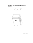
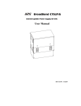
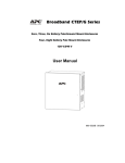
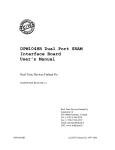
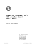
BroadBand CTFRP
Ferroresonant Power Supply
User Manual
990-5516A 10/2004
Chapter 1 General Information
The CTFRP Series Power Supply provides a power source for broadband cable operations.
Important Safety Instructions – Save These Instructions
This Safety Guide contains important instructions that should be followed during installation and
maintenance of the APC equipment and batteries. It is intended for APC customers who setup,
install, relocate, or maintain APC equipment.
Changes and modifications to this unit not expressly approved by APC could void the
warranty.
Failure to observe these warnings may result in serious injury, death or damage to the
equipment.
Do not work alone under hazardous conditions.
Electrical
Warnings
Do not handle any metallic connector before the power has been disconnected.
Servicing this equipment may require working with protective covers removed
and AC power connected. Use extreme caution during these procedures.
High short circuit current through conductive materials could cause severe
burns.
When grounding cannot be verified, disconnect the equipment from the utility
power outlet before installing or connecting to other equipment. Reconnect the
power cord only after all connections are made.
Check that the power cord(s), plug(s), and sockets are in good condition.
Replacement of fuses or other parts must be with identical types and ratings.
Substitution of nonidentical parts may cause safety and fire hazards.
Overhead
Warnings
Never stand underneath anything while it is being hoisted.
Always wear a hard hat.
Lifting
Warnings
Transformer modules are heavy. Use proper lifting techniques to avoid injury.
Unpacking
Inspect the unit upon receipt. Notify the carrier if there is damage.
The packaging is recyclable; save it for reuse or dispose of it properly.
Check the package contents. The package contains the Power Supply and product documentation.
1
990-5516A 10/2004
Specifications
Environmental Specifications
Operating Temperature
-40º F to +140º F (-40º C to +60º C)
Humidity
5% to 95% noncondensing within enclosure
Physical Specifications
Characteristic
Specification
Height
CTFRP6XXX
CTFRP9015
11.5″ (29 cm)
13” (33 cm)
Width
CTFRP6XXX
CTFRP9015
6″ (15 cm)
7” (18 cm)
Depth
CTFRP6XXX
CTFRP9015
6″ (15 cm)
9.5” (24 cm)
Weight
CTFRP6XXX
CTFRP9015
37 lbs (16 kg)
65 lbs (29 kg)
Models Supported
CTFRP6009
FRP 120 VAC, 60 Hz, 60 V, 9 A
CTFRP6015
FRP 120 VAC, 60 Hz, 60 V, 15 A
CTFRP6509
FRP 230 VAC, 50 Hz, 60 V, 9 A
CTFRP6515
FRP 230 VAC, 50 Hz, 60 V, 15 A
CTFRP6615-0
FRP 240 VAC, 60 Hz, 60 V, 15 A
CTFRP9015-0
FRP 120 VAC, 60 Hz, 90 V, 15 A
2
990-5516A 10/2004
Chapter 2 Installation and Maintenance
Only trained service personnel should install and maintain the Power Supply.
Prior to installing the Power Supply, an APC approved enclosure must be installed and AC line
voltage must be routed to the enclosure. Local, state, federal and/or National Electric Code (NEC)
regulations regarding location, permits and electrical wiring must be adhered to.
Do not operate the Power Supply where the temperature and humidity are outside the specified
limits. See Specifications in this manual.
Front View
Side View
Installing the Power Supply
Enclosure Installation
Bottom View
Line Input
Output Indicator
Cable Adapter
Ground Lug
Mounting Screw
1.
Remove the screw holding the key on the rear of the chassis.
2.
Remove the 10-32 Phillips mounting screw that secures the bracket to the housing.
3.
Remove the mounting bracket from the housing by pulling down.
4.
Set the Power Supply and the key aside.
5.
Refer to Specifications in this manual for Power Supply dimensions.
3
990-5516A 10/2004
6.
Locate the position on the pole where the Power Supply is to be located.
7.
Drill two 3/4” holes vertically spaced 6” (15.2 cm) apart.
8.
Attach the top of the mounting bracket to the pole using a 5/8” pole bolt and washer. Repeat this
procedure for the bottom of the bracket.
9.
Ensure that the power supply enclosure is closed and locked.
10. Holding the Power Supply above the bracket slide the unit down the bracket. The lip of the
bracket must slide under the lip at the top of the Power Supply cabinet.
11. Replace the 10-32 Philips screw (removed in step 2 above).
Wiring
1.
Unlock the FRP enclosure. Let the lid slide down and then pull out at the top. The lid will
remain attached to the Power Supply.
2.
Check the line power switch to ensure that it is OFF.
3.
Install a pin type connector (not furnished) in the chassis connector located on the bottom of the
Power Supply.
4.
Attach the yellow wire with the clamp to the stinger of the pin connector. Tighten the setscrew
on the lug clamp.
5.
Place #6 copper ground wire into the ground lug located on the bottom of the cabinet.
6.
Route and attach the ground wire according to local electrical codes.
7.
Install an approved 20 amp high magnetic circuit breaker on the input power side of the power
supply.
8.
Install conduit into the opening on the bottom and attach line power in accordance with local
electrical codes. The barrier strip is wired with the hot leg at the top. The bottom connector is
chassis ground.
4
990-5516A 10/2004
Chapter 3 Operation
CTFRP-6XXX Series
#370 T - 1
TWI
14 AWG
14 AWG
BLK
BLK
#210
15A BREAKER/SW
SW 1:2
WHT
SW 1:1
TW2
MOV
#260
C – 1 #380
C 1:1
TW3
15UF
C 12
14 AWG
RED TW5
VIL
12 AWG TW4
GRN/YEL 15 AWG
RED
14 AWG TW6
16 AWG
BRN
GRN/YEL
GRN
W7
YEL
GND - 1
OUTPUT OPTION
CONNECTOR
JUMPERED IF NOT
USED
1 GN
VIL
W1
YEL
12 AWG
W4
W3
18 AWG
GRN
BLK
WHT 14 AWG
16 AWG W2
GRN/YEL
1
2
3
16 AWG
GRN/YEL
W6
GND - 2
2
IN
3
OT
J2
WS
1B
BLK/WHT
#110
LT1
LT-1
P2
LT-1
J1
60 VAC RMS
L N G
LINE IN
OUTPUT TO CABLE
INPUT FROM BREAKER
5
990-5516A 10/2004
CTFRP-90XXX Series
Initial Start-up
1.
Turn the utility breaker to the ON position.
2.
Turn the power supply switch to the ON position. Note: The output indicator located at the
bottom of the unit is illuminated.
3.
Using a True RMS voltmeter check for voltage at the stinger lug. The unit is now operational.
To shut down the Power Supply
1.
Move the power supply switch to the OFF position.
2.
Move the utility circuit breaker to the OFF position.
6
990-5516A 10/2004
Chapter 4 Service, Contact and Warranty Information
Service
APC makes every effort to ensure parts and equipment arrive in working condition. Occasionally, it
may be necessary to return parts or equipment that are not in working condition.
If the unit requires service do not return it to the dealer. Follow these steps:
1.
Contact APC Customer Support through the APC Web site, www.apc.com/support.
Note the product model number, the serial number, and the date purchased. If you call APC
Customer Support, a technician will ask you to describe the problem and try to solve it over
the phone. If this is not possible the technician will issue a Returned Material Authorization
Number (RMA#).
If the product is under warranty, repairs are free. If not, there is a repair charge.
Procedures for servicing or returning products may vary internationally. Refer to the APC
Web site. Select the appropriate country from the country selection field. Select Support
from the tab at the top of the web page.
2.
Pack the product in its original packaging. If the original packing is not available, refer to the
APC Web site for information on obtaining appropriate packing materials.
Pack the unit properly to avoid damage in transit. Never use Styrofoam beads for packaging.
Damage sustained in transit is not covered under warranty.
3.
Mark the RMA# on the outside of the package.
4.
Return the unit by insured, prepaid carrier to the address given to you by Customer Support.
How to Contact APC
In the USA …
Outside the USA …
Refer to the APC Web site, Refer to the APC Web site, www.apc.com. Select the appropriate
www.apc.com/support.
country from the country selection field. Select the Support tab at
the top of the web page.
7
990-5516A 10/2004
Limited Warranty
American Power Conversion (APC) warrants its products to be free from defects in materials and workmanship for a period of
two years from the date of purchase. Its obligation under this warranty is limited to repairing or replacing, at its own sole
option, any such defective products. To obtain service under warranty you must obtain a Returned Material Authorization
(RMA) number from customer support. Products must be returned with transportation charges prepaid and must be
accompanied by a brief description of the problem encountered and proof of date and place of purchase. This warranty does
not apply to equipment that has been damaged by accident, negligence, or misapplication or has been altered or modified in
any way. This warranty applies only to the original purchaser who must have properly registered the product within 10 days of
purchase.
EXCEPT AS PROVIDED HEREIN, AMERICAN POWER CONVERSION MAKES NO WARRANTIES, EXPRESSED OR
IMPLIED, INCLUDING WARRANTIES OF MERCHANTABILITY AND FITNESS FOR A PARTICULAR PURPOSE.
Some states do not permit limitation or exclusion of implied warranties; therefore, the aforesaid limitation(s) or exclusion(s)
may not apply to the purchaser.
EXCEPT AS PROVIDED ABOVE, IN NO EVENT WILL APC BE LIABLE FOR DIRECT, INDIRECT, SPECIAL,
INCIDENTAL, OR CONSEQUENTIAL DAMAGES ARISING OUT OF THE USE OF THIS PRODUCT, EVEN IF
ADVISED OF THE POSSIBILITY OF SUCH DAMAGE. Specifically, APC is not liable for any costs, such as lost profits or
revenue, loss of equipment, loss of use of equipment, loss of software, loss of data, costs of substitutes, claims by third parties,
or otherwise.
Regulatory Approval
Entire contents copyright © 2002 by American Power Conversion Corporation. All rights reserved. Reproduction in whole or
in part without permission is prohibited.
APC is a registered trademark of American Power Conversion Corporation. All other trademarks are the property of their
respective owners.
8
990-5516A 10/2004