1
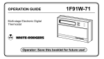
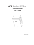
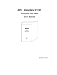
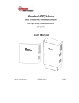
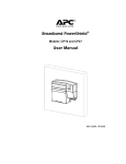
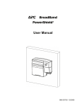
BroadBand CTSLP/G
Uninterruptible Power Supply 60 VAC
User Manual
990-5518A 10/2004
Chapter 1 General Information
The SLP/G Series Standby Power Supply provides an uninterruptible power source for broadband
cable operations. Batteries are housed inside the module. A battery vault may be used to provide
additional battery backup. Refer to the APC Web site, www.apc.com for detailed information on
additional battery configurations.
Important Safety Instructions – Save These Instructions
This Safety Guide contains important instructions that should be followed during installation and
maintenance of the APC equipment and batteries. It is intended for APC customers who setup,
install, relocate, or maintain APC equipment.
Changes and modifications to this unit not expressly approved by APC could void the
warranty.
Failure to observe these warnings may result in serious injury, death or damage to the
equipment.
Do not work alone under hazardous conditions.
Electrical
Warnings
Do not handle any metallic connector before the power has been disconnected.
Servicing this equipment may require working with protective covers removed
and AC power connected. Use extreme caution during these procedures.
High short circuit current through conductive materials could cause severe
burns.
When grounding cannot be verified, disconnect the equipment from the utility
power outlet before installing or connecting to other equipment. Reconnect the
power cord only after all connections are made.
Check that the power cord(s), plug(s), and sockets are in good condition.
Replacement of fuses or other parts must be with identical types and ratings.
Substitution of nonidentical parts may cause safety and fire hazards.
Overhead
Warnings
Never stand underneath anything while it is hoisted. Always wear a hard hat.
Lifting
Warnings
Transformer modules are heavy. Use proper lifting techniques to avoid injury.
Battery
Warnings
Danger of explosion if battery is incorrectly connected or replaced. Replace
batteries only with same or equivalent type recommended by the
manufacturer. Dispose of used batteries according to the manufacturer’s
instructions.
1
990-5518 03/02
Specifications
Environmental Specifications
Operating Temperature
-40º F to +140º F (-40º C to +60º C)
Humidity
5% to 95% noncondensing within enclosure
Physical Specifications
Characteristic
Specification
Height
Pole Mount
Ground Mount
18″ (45.7 cm)
25” (33 cm)
Width
Pole Mount/Ground Mount
23″ (58.4 cm)
Depth
Pole Mount/ Ground Mount
16″ (41 cm)
Weight
Pole Mount
without batteries
with 3 batteries
Ground Mount
without batteries
with 3 batteries
82 lbs (37.2 kg)
154 lbs (70 kg)
92 lbs (41.8 kg)
164 lbs (75.5 kg)
Electrical Specifications
Input Characteristic
Input Specification
Input Voltage
120 VAC Nominal
220 VAC Nominal
Input Current
15 A Max
Input Frequency
60 Hz ± 1 Hz
Output Characteristic
Output Specification
Output Voltage
60 VAC ± 3%
Output Current
9 A/15 A
Output Frequency
60 Hz ± 1%
Output Regulation
Normal
Standby
± 3%
± 5%
Output Protection
20 A Circuit Breaker (optional)
Transfer Time
<20 milliseconds
2
990-5518 03/02
Chapter 2 Installation and Maintenance
Only trained service personnel should install and maintain the Power Supply.
Prior to installing the Power Supply AC line voltage must be routed to the enclosure. Local, state,
federal and/or National Electric Code (NEC) regulations regarding location, permits and electrical
wiring must be adhered to.
Do not operate the Power Supply where the temperature and humidity are outside the specified
limits. See Specifications in this manual.
Unpacking
Inspect the unit upon receipt. Notify the carrier if there is damage.
The packaging is recyclable; save it for reuse or dispose of it properly.
Check the package contents. The package contains the Power Supply and product documentation.
SLG Enclosure
SLP Enclosure
Mounting Bracket
Models Supported
Model Number
Description
CTSLGH220S1
ENCL, SLG, 36V, 220VAC, SM Ready
CTSLPH120S1
ENCL, SLP, 36V, 120VAC, SM Ready
CTSLPH220S1
ENCL, SLP, 36V, 220VAC, SM Ready
CTSLGH710S1
ENCL, SLG, 36V, 120VAC, SM Ready
Installing the Power Supply Enclosure
Use 2” conduit with an outer diameter of 2.5” (5.1 cm/6.4 cm). The mounting holes are 1/2” in
diameter.
3
990-5518 03/02
SLG Enclosure Installation
Locate an installation site and setup the concrete pad according to local building code requirements.
See the figure below for pad details.
Use 3/8” threaded rod,
“J” hooks, or
foundation bolts in the
concrete (1.27 cm).
1.
Remove the rear panel of the ground mount skirt (four, #8 Phillips head screws).
2.
Pull the Coax and AC lines through the sweeps.
3.
Set the enclosure onto the rods set in the concrete pad.
4.
Secure the enclosure using lockwashers and nuts.
5.
Apply a sealant to the concrete pad/ ground skirt to seal the interior of the enclosure against
moisture and insects.
4
990-5518 03/02
SLP Enclosure Installation
Top Hole
.75” (1.9 cm)
11.5” (29.2 cm)
Bottom Hole
.75” (1.9 cm)
Bottom Edge of
Housing
Mounting Bracket is permanently
attached to enclosure.
Wall Mount Units: Select fasteners that will accommodate the weight of the unit including batteries.
Wiring
Unlock and open the enclosure door. The open door is designed to either rest on the top edge of the
enclosure or slide into the enclosure.
Install an approved 20 amp high magnetic circuit breaker between the power source and the power
supply unit.
1.
Attach conduit to the 1/2 “ hole on the bottom of the unit and wire the input line.
2.
Connect the wires to the Euro block.
3.
Route the power feed Coax to the bottom of the enclosure. Install a pin type connector (not
furnished), to the chassis connector located on the bottom of the enclosure.
4.
Attach the yellow wire with the clamp to the stinger of the pin connector. Tighten the setscrew
on the lug clamp.
5.
Place suitable copper ground wire into the ground lug located on the bottom of the enclosure.
Route and attach the ground wire.
6.
Switch the AC circuit breaker to the ON position.
7.
Check voltages between pins 6, 4, 3, 2, and 1 on the ferro connector and the ground. If voltages
are present, repeat step 7 above.
5
990-5518 03/02
Installing Batteries
Ensure that the battery breaker is in the OFF position during battery installation.
The batteries fit into a battery tray that is installed on the top shelf of the enclosure.
The Thermal Switch provides temperature control during battery charge. Place the Thermal Switch at
the top of the batteries.
Install the batteries with the polarities oriented properly. See figure below.
Thermal Switch
Battery Breaker Switch
2: Black Lead from Harness
1: Red Lead from Harness
4: Black Lead
5: Red
Lead
Battery #1
3: Red Jumper
Battery #2
6
Battery #3
990-5518 03/02
Installing Modules
Batteries
Status Monitor
Transponder
(optional)
Standby Module (SLM)
Ferroresonant
Module (FLM)
Ferroresonant Module Installation
1.
Switch the AC circuit beaker to the OFF position.
2.
Locate the pin connector on the enclosure. Slide the FLM into the enclosure. The guide pin on
the FLM will snap into the connector on the enclosure.
3.
Switch the AC circuit beaker to the ON position.
4.
Switch the breaker located on the front of the FLM, to the ON position. The green lamp on the
bottom of the enclosure will illuminate.
5.
Verify voltage at the stinger connector. Refer to Specifications in this manual.
Standby Module Installation
1.
Ensure that the batteries are connected properly and the battery circuit breaker is in the OFF
position.
2.
Locate the pin connector on the enclosure. Slide the SLM into the enclosure. The guide pin on
the SLM will snap into the connector on the enclosure.
3.
Switch the battery circuit breaker to the ON position.
Note: Batteries charge during normal operation.
7
990-5518 03/02
Chapter 3 Operation
Initial Startup
1.
Switch the AC circuit breaker to the ON position.
2.
Verify that the FLM and SLM circuit breakers are switched to the ON position.
3.
Allow 15 seconds for the SLM to run through the time delay cycle.
4.
Check the battery float voltage on the charger card at TP1 and TP2.
If adjustment is necessary, switch the battery circuit breaker to the OFF position. Attach test
leads to TP1 (red) and TP2 (black), adjust potentiometer R2 for correct reading. Switch the
battery circuit breaker to the ON position.
5.
Measure the voltage at the Coax connector ensuring that 60 VAC are present.
Verify SLM Operation
Allow the batteries to charge for 24 hours prior to testing.
Switch the FLM circuit breaker to the OFF position. The red lamp will illuminate and the SLM will
begin standby mode operation.
Shut Down
Switch the battery circuit breaker, the FLM circuit breaker, and the AC line circuit breaker to the
OFF positions.
Auxiliary Power Supply
1.
Set up an auxiliary AC generator and calibrate to 60 Hz ± 1 Hz.
2.
Turn the AC main breaker to the OFF position.
3.
Unplug the AC input cord from the FLM and attach it to the generator extension cord.
4.
The green lamp on the bottom or the enclosure will illuminate.
For details regarding available options see the APC Web site www.apc.com.
8
990-5518 03/02
X
FLM
Y
Z
[
]
Index
\
Item
Description
1
Auxiliary AC Input Plug
Provides connection point to operate Power Supply from a generator.
2
AC Auxiliary Receptacle
Provides access to utility power for field tools, lights, etc.
3
Ammeter (optional)
Displays output current while in normal mode.
4
15 A Breaker
Provides input surge protection.
5
Option Plug
Provides an interface for standard APC power supply options.
6
Voltmeter (optional)
Displays output voltage while in normal mode.
SLM
[
Z
Y
X
Index
Item
Description
1
Charger Card
Contains circuits used to: maintain a charge on the batteries, sense input power
loss and provide logic to determine mode of operation.
2
Inverter Card
Contains circuits that receive DC input from the batteries and provide AC
output during standby operation.
3
Event Counter (optional)
Displays number of transitions from normal to standby operation.
4
Hour Meter (optional)
Displays total time in standby operation.
9
990-5518 03/02
SLP/G Enclosure Bottom View
X
Y Z [
\ ]
^
Index
Item
Description
1
AC input
Entry point for AC line conduit.
2
Normal/Main
Indicator LED
Green LED, illuminates during normal operation of FLM power supply.
3
Standby/Main
Red LED, illuminates during SLM backup operation.
4
Output Cable Adapter
Coax adapter for FLM power supply output.
5
Ground Wire Lug
Ground wire attachment.
6
FLM Output/Secondary
(optional)
Coax adapter for secondary FLM connection.
7
Normal/Secondary Indicator
LED
Green LED, illuminates during operation of secondary FLM power supply.
8
Status Monitoring Connector
(optional)
Connector space for Status Monitor option.
10
990-5518 03/02
Chapter 4 Service, Contact and Warranty Information
Service
APC makes every effort to ensure parts and equipment arrive in working condition. Occasionally, it
may be necessary to return parts or equipment that are not in working condition.
If the unit requires service do not return it to the dealer. Follow these steps:
1.
Contact APC Customer Support through the APC Web site, www.apc.com/support.
Note the product model number, the serial number, and the date purchased. If you call APC
Customer Support, a technician will ask you to describe the problem and try to solve it over
the phone. If this is not possible the technician will issue a Returned Material Authorization
Number (RMA#).
If the product is under warranty, repairs are free. If not, there is a repair charge.
Procedures for servicing or returning products may vary internationally. Refer to the APC
Web site. Select the appropriate country from the country selection field. Select Support
from the tab at the top of the web page.
2.
Pack the product in its original packaging. If the original packing is not available, refer to the
APC Web site for information on obtaining appropriate packing materials.
Pack the unit properly to avoid damage in transit. Never use Styrofoam beads for packaging.
Damage sustained in transit is not covered under warranty.
3.
Mark the RMA# on the outside of the package.
4.
Return the unit by insured, prepaid carrier to the address given to you by Customer Support.
How to Contact APC
In the USA …
Outside the USA …
Refer to the APC Web site, Refer to the APC Web site, www.apc.com. Select the appropriate
www.apc.com/support.
country from the country selection field. Select the Support tab at
the top of the web page.
11
990-5518 03/02
Limited Warranty
American Power Conversion (APC) warrants its products to be free from defects in materials and workmanship for a period of
two years from the date of purchase. Its obligation under this warranty is limited to repairing or replacing, at its own sole
option, any such defective products. To obtain service under warranty you must obtain a Returned Material Authorization
(RMA) number from customer support. Products must be returned with transportation charges prepaid and must be
accompanied by a brief description of the problem encountered and proof of date and place of purchase. This warranty does
not apply to equipment that has been damaged by accident, negligence, or misapplication or has been altered or modified in
any way. This warranty applies only to the original purchaser who must have properly registered the product within 10 days of
purchase.
EXCEPT AS PROVIDED HEREIN, AMERICAN POWER CONVERSION MAKES NO WARRANTIES, EXPRESSED OR
IMPLIED, INCLUDING WARRANTIES OF MERCHANTABILITY AND FITNESS FOR A PARTICULAR PURPOSE.
Some states do not permit limitation or exclusion of implied warranties; therefore, the aforesaid limitation(s) or exclusion(s)
may not apply to the purchaser.
EXCEPT AS PROVIDED ABOVE, IN NO EVENT WILL APC BE LIABLE FOR DIRECT, INDIRECT, SPECIAL,
INCIDENTAL, OR CONSEQUENTIAL DAMAGES ARISING OUT OF THE USE OF THIS PRODUCT, EVEN IF
ADVISED OF THE POSSIBILITY OF SUCH DAMAGE. Specifically, APC is not liable for any costs, such as lost profits or
revenue, loss of equipment, loss of use of equipment, loss of software, loss of data, costs of substitutes, claims by third parties,
or otherwise.
Regulatory Approval
Entire contents copyright © 2002 by American Power Conversion Corporation. All rights reserved. Reproduction in whole or
in part without permission is prohibited.
APC is a registered trademark of American Power Conversion Corporation. All other trademarks are the property of their
respective owners.
12
990-5518 03/02