1
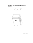
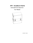
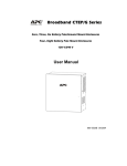
Broadband PowerShield® Models: CP16 and CP27 User Manual 990-2366A 04/2006 Chapter 1: General Information The PowerShield® provides a power source for broadband telephony, Fiber-to-the-Home/Premise (FTTH/P), and other direct current (DC) equipment/applications. Safety This manual contains important instructions that should be followed during installation and maintenance of the APC equipment and batteries. It is intended for APC customers that set up, install, relocate, or maintain APC equipment. Changes and modifications to this unit not expressly approved by APC could void the warranty. Failure to observe this warning may result in serious injury, death, or damage to the equipment. Electrical Warnings Do not work alone under hazardous conditions. Servicing the PowerShield may require the removal of protective covers, as well as connected utility power. Use extreme caution during these procedures. Check that the power cord(s), plug(s), and sockets are in good condition. Replacement of fuses or other parts must be with identical types and ratings. Substitution of nonidentical parts may cause safety and fire hazards. Battery Warning Danger of explosion if the battery is incorrectly connected or replaced. Use only APC replacement batteries. Unpacking Inspect the unit upon receipt. Notify the shipping carrier or product supplier if there is damage. The packaging is recyclable; save it for reuse or dispose of it properly. Check the package contents. The package contains the enclosure, the battery (to be installed), one power cord, and the product documentation. 1 Specifications General Model Number Input Output Maximum Signal Voltage Maximum Signal Current Battery Type CP16U48 100-240 V 50/60 Hz 1.0 A 48 V 16 W 30 V 5 mA CP27U13 100-240 V 50/60 Hz 1.0 A 13 V 27 W 30 V 5 mA 12 V 7.2 AHr Spill-Proof, MaintenanceFree, Sealed Lead Acid Environmental Operating Temperature -4º F to 122º F (-20º C to 50º C) Operating Humidity 5 to 95% noncondensing within enclosure Maximum Operating Elevation 10,000 ft (3,000 m) Maximum Storage Elevation 50,000 ft (15,000 m) Storage Temperature -4º F to 122º F (-20º C to 50º C) *Battery lifetime is reduced with prolonged storage in high temperature (>25º C). Physical Height x Width x Depth PowerShield 7.5 x 9.5 x 3 in (19 x 24 x 7.6 cm) PowerShield carton 13.5 x 13.5 x 4.5 in (34 x 34 x 11 cm) Weight PowerShield 7.15 lbs (3.25 kg) PowerShield with package materials 9 lbs (4 kg) 2 Chapter 2: Installation Enclosure Installation Install the enclosure in a protected area that is free of excessive dust and has adequate airflow. Do not operate the PowerShield where the temperature and humidity are outside the specified limits. See Specifications. Indoor Use Only ! " # Battery Cover Release Tabs $ Use screws that are appropriate for the weight of this unit and the mounting surface material. See Specifications. 3 Battery Installation ! " # Red Cable Positive Terminal Battery Cover Release Tabs $ % 4 Black Cable Negative Terminal Connect Equipment and Power The PowerShield battery charges when it is connected to utility power. The battery charges fully during the first eight hours of normal operation. Do not expect full battery run capability during this initial charge period. Utility Power Cord Inlet Output Power and Communication Signals Optional Runtime Extension Connector 1. Connect the PowerShield to the application equipment (example: FTTH/P Optical Network Terminal) via the seven-pin output connector, using the appropriate cable (must be ordered separately). See www.apc.com for a list of available output cables. 2. Plug the PowerShield power cord into the utility power cord inlet and then into the wall outlet. Do not overload the wall outlet or circuit. Cold Start Feature: Upon installation of a charged battery, power will immediately be applied to the unit even when utility power is not present. Optional Runtime Extension The runtime may be extended by adding the external battery CP20B12BP. 5 Chapter 3: Operation Status Indicators and Features Front Panel Status Indicators Indicator Description Utility Solid green indicates the unit is on utility power. Solid yellow indicates that utility power is not present and the unit is on battery power. Flashing green LED indicates the unit is fast-charging. Output Green indicates the unit is working properly and DC output power is provided by the battery or the utility power. Replace Battery/ Alarm Silence Red indicates that the battery must be replaced or that the battery is disconnected. See Battery Replacement. Pressing this button will silence the audible alarm. See Alarm Silence Button. / Automatic Self-Test The unit automatically performs a self-test 31 hours after initial installation. Following this, a battery self-test will occur every 30 days. See Alarm Silence Button for manual self-test information. Audible Alarm Explanation Description On Battery Four beeps in four seconds will be emitted one time only. This alarm will sound when the utility power is lost and the unit goes on battery power. Low Battery Voltage Every five minutes, four beeps in four seconds will be emitted. This alarm will sound when operating on battery and the battery voltage has dropped below threshold, indicating that less than 20% of available runtime remains. Replace Battery Every fifteen minutes, there will be a quarter-second beep when the battery fails the automatic self-test. 6 Alarm Silence Button The audible alarms may be silenced by utilizing the dual function Replace Battery/Alarm Silence LED/button / . Function Button Operation (Press and hold for:) Description Replace BatteryTemporarily Enable/Disable <4 seconds If the alarm has been silenced, the unit will emit one quick beep. If the alarm has been enabled, two quick beeps will be emitted. Replace BatteryPermanently Enable/Disable 8-12 seconds If the alarm has been silenced, the unit will emit one quick beep. If the alarm has been enabled, two quick beeps will be emitted. If the self-test has been enabled, three beeps will be emitted. If the self-test cannot be enabled, a single beep will be emitted.* If the battery self-test has been canceled, the unit will emit four beeps. *A battery self-test cannot be enabled unless the following conditions have been met. 1. Battery has been charged for at least 31 hours. 2. The unit has been on utility power for more than 12 hours. 3. Temperature is between 0 and 50°C. Battery Self-TestEnable/Disable 4-8 seconds Output Power and Communication Signals The PowerShield communication signals are isolated from its internal circuitry via open collector opto-coupled transistors. The connection labeled “Signal Return” is a common return point for all communication signals. In the typical application, the attached equipment digital ground connects to Signal Return, and pull-up resistors turn the open collector signals into logic levels. +Voltage output Voltage output Signal return. Low when operating from utility line. Open when operating from battery. Low when battery is charged. Open when battery fails the Self-Test. Low when battery is present. Open when battery is missing. Low when battery is near full charge capacity. Open when operating from a battery with less than 20% of available runtime remaining. 7 Chapter 4: Maintenance, Service, Approvals, and Warranty Battery Replacement This unit has an easy to replace, hot-swappable battery. Replacement is a safe procedure, isolated from electrical hazards. You may leave the unit and connected equipment on for this procedure. During the self-test, battery removal and replacement are not recommended. For self-test disabling, see Alarm Silence Button. Replace the spent battery with APC replacement battery RBC2. See your dealer or refer to the APC Web site, www.apc.com, for information on replacement batteries. For battery replacement, see Battery Installation. Once the battery is disconnected, the connected equipment is not protected from power outages. Be sure to deliver spent batteries to a recycling facility found on the Used Battery Return Facilities list included with RBC2. Service APC makes every effort to ensure parts and equipment arrive in working condition. Occasionally, it may be necessary to return parts and equipment that are not in working condition. If the PowerShield requires service, follow these steps: 1. Contact APC Customer Support through the APC Web site at www.apc.com. Note the product model number, the serial number, and the date purchased. If you call APC Customer Support, a technician will ask you to describe the problem and try to solve it over the phone. If this is not possible, the technician will issue a Returned Material Authorization Number (RMA#). If the product is under warranty, repairs are free. If not, there is a repair charge. Procedures for servicing or returning products may vary internationally. Refer to the APC Web site. Select the appropriate country from the country selection field. Select Support from the tab at the top of the web page. 2. Pack the product in its original packaging. Pack the unit properly to avoid damage in transit. Never use Styrofoam beads for packaging. Damage sustained in transit is not covered under warranty. 3. Mark the RMA# on the outside of the package. 8 4. Return the unit by insured, prepaid carrier to the address given to you by Customer Support. Always DISCONNECT THE BATTERY before shipping in compliance with U.S. Department of Transportation (DOT) regulations. Contact Information Refer to the APC Web site, www.apc.com. Regulatory Approvals 9 Limited Warranty American Power Conversion (APC) warrants its products to be free from defects in materials and workmanship for a period of two years from the date of purchase. Its obligation under this warranty is limited to repairing or replacing, at its own sole option, any such defective products. To obtain service under warranty you must obtain a Returned Material Authorization (RMA) number from customer support. Products must be returned with transportation charges prepaid and must be accompanied by a brief description of the problem encountered and proof of date and place of purchase. This warranty does not apply to equipment that has been damaged by accident, negligence, or misapplication or has been altered or modified in any way. This warranty applies only to the original purchaser who must have properly registered the product within 10 days of purchase. EXCEPT AS PROVIDED HEREIN, AMERICAN POWER CONVERSION MAKES NO WARRANTIES, EXPRESSED OR IMPLIED, INCLUDING WARRANTIES OF MERCHANTABILITY AND FITNESS FOR A PARTICULAR PURPOSE. Some states do not permit limitation or exclusion of implied warranties; therefore, the aforesaid limitation(s) or exclusion(s) may not apply to the purchaser. EXCEPT AS PROVIDED ABOVE, IN NO EVENT WILL APC BE LIABLE FOR DIRECT, INDIRECT, SPECIAL, INCIDENTAL, OR CONSEQUENTIAL DAMAGES ARISING OUT OF THE USE OF THIS PRODUCT, EVEN IF ADVISED OF THE POSSIBILITY OF SUCH DAMAGE. Specifically, APC is not liable for any costs, such as lost profits or revenue, loss of equipment, loss of use of equipment, loss of software, loss of data, costs of substitutes, claims by third parties, or otherwise. Entire contents copyright 2006 by American Power Conversion Corporation. All rights reserved. Reproduction in whole or in part without permission is prohibited. APC, the APC logo and PowerShield are registered trademarks of American Power Conversion Corporation. All other trademarks are the property of their respective owners. 10