1
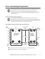
Electrical Installation – Communication Wiring to EPO and Optional
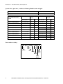
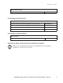
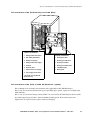
Pin connections J106 (XR Enclosure) and J108 (EPO)
J106 Pin Connections:
1
Battery measurement return*
J108 Pin Connections:
2
Max. battery temperature*
1
Normally open EPO
3
Battery unit quantity*
2
Normally open EPO return
4
Battery measurement supply*
3
Normally closed EPO
5
Q3 active
4
Normally closed EPO return
6
Q3 active return
5
+24V SELV supply
7
External control of charging
6
SELV ground
8
Ext. charging control return
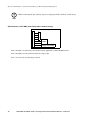
* Should be used with APC XR
Enclosures only
Pin connections J106 (UPS) to J200 (XR Enclosure - option)
Pins 1 through 4 are for battery measurement (only applicable to APC XR Enclosures).
Pins 5 & 6 are for external maintenance bypass Q3. When Q3 is closed, signals are fed back to the
UPS controller.
Pins 7 & 8 are for external charge control. When 7 & 8 are closed, the UPS charges batteries with a
pre-defined percentage (0-100%) of the maximum charging power. To be used in generator
applications, or if special codes requires control of charging.
AIS® 3000 10-30kVA, 208V, Site Preparation and Installation Manual – 990-1957
37