1
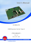
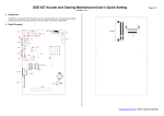
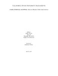
Quick Guide
POS50 Series
April. 2006 (V1.0)
1
CONTENTS
Chapter 1 Unpacking
-------------------------------------------------------------------------------- 3
Chapter 2 Specification
-------------------------------------------------------------------------------- 4
2.1 Specification
2.2 I/O Ports
Chapter 3 Installation
--------------------------------------------------------------------------------- 6
3.1 OS Installation
3.2 Touch Driver Installation
3.3 MSR / I Button PS2 Interface Installation
3.4 Cash Drawer
Chapter 4 Jumper Definition
-----------------------------------------------------------------14
4.1 Main Board Layout
4.2 LCD Power Setting
4.3 COM1/2 Power Selection
4.4 COM 3 Power Selection
4.5 IDE Disk Drive Connector
4.6 FAN Connector
4.7 Serial Port
4.8 Power Connector
4.9 VGA connector
4.10 LCD & Inverter Connector
4.11 USB Port Connector
4.12 Audio Connector
4.13 LED
4.14 Power & Reset Button
4.15 Cash Drawer
4.16 Keyboard & Mouse Connector
4.17 Touch Connector
2
Chapter 1
Unpacking
Unpacking the POS Terminal, please check the following items are presented and in good conditions:
a. Main Unit
b. CD: User’s Manual & Driver Bank
The driver disk includes user’s manual and all of driver software of peripheral, such as touch
screen, VGA, LAN….etc.
c.
Power Cord: Optional USA, Europe, UK or Australia type.
3
Chapter 2
Specification
2.1 Specification
The POS system configuration including 8.4”, 12.1” and 15” as followings,
CPU
System Memory
TFT LCD Size
Brightness
Resolution
Touch Screen
HDD
Compact Flash
Serial
Main Board
AMD Geode LX-800
1 x DDR400 SO-DIMM Socket, up to 1GB
Display
8.4”
12.1”
15”
180nits
300nits
250nits
800x600
1024x768
5 Wire Resistive Type
Storage Device
No Support
2.5” Slim Type
1 x Type II, Slot
I/O Ports
2x RS232 (Pin9 with 5/12V Selected)
2x RS232 (Internal Touch & MSR Used)
USB
2 x USB2.0
2 x USB2.0 Internal Stand By
LAN
Cash Drawer
Audio
Power Supply
Compliance
Weight (Kgs)
Operating Temperature
1 x RJ45, 10/100 Base-T
1 x RJ11 (Power 12V)
AC97 2.0 Compliant, Speaker 2 x 2W
Others
Internal Adapter, 12V / 80W, ATX
FCC / CE
1.8
3.2
5 ~ 40 ゚ C
Wireless LAN
MSR
Optional Accessory
802.11g, USB I/F
ISO STD 3 Tracks, KB I/F
4
4.4
2.2 I/O ports
Following ports show all of ports of system.
a. DC IN: connector for power adapter input 12VDC.
b. Cash Drawer: provide IO port address 280H for cash drawer control by RJ11.
c.
COM 1/2: standard D sub serial port with 5V / 12VDC selected on pin9.
d. LAN: 10 / 100 base-T by RJ45 connector.
e. USB: play and plug USB 2.0.
f.
Power Switch: toggle switch for power on.
g. MSR PS2: for attached MSR PS2 interface connection.
5
Chapter 3
Installation
3.1 OS Installation
3.1.1 Embedded WEPOS / WinCE
CD ROM Driver with USB interface
If you bought the system including WEPOS / WinCE operation system, please follow up
below procedure.
a. Connect CDROM to the USB port of system.
b. Turn on the system and enter completely into WEPOS.
c. Up load your application software into WEPOS platform.
d. Complete installation and execute the AP.
Note: We suggest that you buy and use factory recommend CD-ROM with USB interface while you are
placed first sample unit.
3.1.2 Win XP
If you would like to install the Win XP, we suggest the system’s configuration include 256MB RAM and
HDD.
a. Connect CDROM to the USB port of system.
b. Turn on the system and press “ Del” key enter to CMOS setup.
c. Select icon “Advanced BIOS Features“.
Phoenix – Award BIOS CMOS Setup Utility
¾
¾
¾
¾
¾
¾
¾
Standard CMOS Features
Advanced BIOS Features
Advanced Chipset Features
Integrated Peripherals
Power Management Setup
PnP / PCI Configuration
PC Health Status
ESC: Quit
F10: Save & Exit Setup
6
d. Select “First Boot Device” to “USB-CDROM”.
e. Press “F10” to save setup change and quit.
f. Install the Win XP, follow up the OS installation guide.
Phoenix – Award BIOS CMOS Setup Utility
Advanced BIOS Features
[Disabled]
Virus Warning
[Enabled]
CPU Internal Cache
[Disabled]
Boot From Lan Control
First Boot Device
[USB-CDROM]
Second Boot Device
[HDD-0]
Third Boot Device
[CDROM]
Boot Other Device
[Enabled]
Boot UP NumLock Status
[On]
Gate A20 Option
[Fast]
Typematic Rate Setting
[Disabled]
Typematic Rate (Chars/Sec)
6
Typematic Delay (Msec)
250
Security Option
[Setup]
OS Select For DRAM > 64MB
[Non-OS2]
Small Logo(EPA) Show
[Disabled]
3.2 Touch Driver Installation
Refer to list procedure of touch driver as followings, which is based on Win XP as example.
7
8
9
10
11
3.3 MSR / I-Button PS2 interface Installation
a. The MSR Kit included Bracket and Module.
b. Turn the system to rear side.
c. Screw up the bracket on the fixed hole.
12
d. Screw up the MSR module and connect the cable into connector.
3.4 Cash Drawer
For the 3rd version M/B which is released from end of April. The cash drawer pin assignment
as followings. In order to program the cash drawer easily, we also provide OPOS driver.
Pin
1
2
3
4
5
6
Assignment
GND
Data Out
Data In
12V
NC
GND
Note:
I/O Address: 280H for Cash Drawer which is controlled by
Data bit: Data IN =>Bit 0, Data OUT=>Bit 1
Normally recommend drive the Cash Drawer by out FF to I/O 280H.
13
Chapter 4
Jumper Definition
4.1 Main Board Layout
14
4.2 LCD Power setting
•
JP2: This jumper is for the setting of LCD panel voltage.
JP2
2-4
4-6
•
Description
+3.3V
+5V
JP2: This jumper is for the setting of LCD panel shift clock.
JP2
1-3
3-5
Description
Inverted
Normal
4.3 COM1/2 Power Selection
JP3
1-3
3-5
7-9
2-4
4-6
8-10
Description
COM1 RI Pin Use +12V
COM1 RI Pin Use +5V
COM1 RI Pin Use RI
COM2 RI Pin Use +12V
COM2 RI Pin Use +5V
COM2 RI Pin Use RI
4.4 COM3 Power Selection
JP4
1-2
5-6
3-4
Description
COM3 RI Pin Use +12V
COM3 RI Pin Use +5V
COM3 RI Pin Use RI
4.5 IDE Disk Drive Connector
•
a. CN10: Primary IDE Connector (Pitch 2.00 mm)
PIN
1
3
5
7
9
11
13
15
17
19
21
23
25
27
29
31
Description
RESET#
DATA 7
DATA 6
DATA 5
DATA 4
DATA 3
DATA 2
DATA 1
DATA 0
GROUND
IDE DREQ
IOW#
IOR#
IDE DRDYA
IDE DACK
INTERRUPT
PIN
2
4
6
8
10
12
14
16
18
20
22
24
26
28
30
32
Description
GROUND
DATA 8
DATA 9
DATA 10
DATA 11
DATA 12
DATA 13
DATA 14
DATA 15
N/C
GROUND
GROUND
GROUND
GROUND
GROUND
N/C
15
33
35
37
39
41
43
SA1
SA0
HDC CS0#
HDD ACTIVE#
VCC5
GND
34
36
38
40
42
44
CABLE_80P
SA2
HDC CS1#
GROUND
VCC5
b. CN8: Compact Flash Storage Card Socket
PIN
1
2
3
4
5
6
7
8
9
10
11
12
13
14
15
16
17
18
19
20
21
22
23
24
25
Description
GROUND
D3
D4
D5
D6
D7
CS1#
N/C
GROUND
N/C
N/C
N/C
VCC
N/C
N/C
N/C
N/C
A2
A1
A0
D0
D1
D2
N/C
CARD DETECT2
PIN
26
27
28
29
30
31
32
33
34
35
36
37
38
39
40
41
42
43
44
45
46
47
48
49
50
Description
CARD DETECT1
D11
D12
D13
D14
D15
CS3#
N/C
IOR#
IOW#
OBLIGATORY TO PULL HIGH
IRQ15
VCC
SLAVE
N/C
RESET#
IORDY
DRQ
ACK
ACTIVE#
PDIAG#
D8
D9
D10
GROUND
4.6 Fan Connector
These connectors can supply +5V/500mA to the cooling fan. In the connector there have a “rotation” pin. The
rotation pin is to get the fan’s rotation signal to system. So the system BIOS could recognize the fan speed.
Please note only specified fan offers the rotation signal.
•
CN11 : Fan connector
PIN
1
2
3
Description
Rotation Signal
VCC5
GND
16
4.7 Serial Ports
The system provides three high speed NS16C550 compatible UARTS with Read/Receive 16 byte FIFO. Four
com ports are in IO connector.
•
•
COM1: CN25 DB9-pin header
COM2: CN26 DB9-pin header
PIN
1
2
3
4
5
6
7
8
9
•
COM2: CN27 pin header 2.0mm
PIN
1
2
3
4
5
6
7
8
9
10
11
12
13
14
•
Description
DATA CARRIER DETECT (DCD)
RECEIVE DATA (RXD)
TRANSMIT DATA (TXD)
DATA TERMINAL READY (DTR)
GROUND
DATA SET READY (DSR)
REQUEST TO SEND (RTS)
CLEAR TO SEND (CTS)
RING INDICATOR (RI)
Description
DATA CARRIER DETECT (DCD)
RECEIVE DATA (RXD)
TRANSMIT DATA (TXD)
DATA TERMINAL READY (DTR)
GROUND
DATA SET READY (DSR)
REQUEST TO SEND (RTS)
CLEAR TO SEND (CTS)
RING INDICATOR (RI)
N/C
+5V
N/C
+12V
GROUND
COM3: CN24 for Card Reader.
PIN
Description
1
GROUND
2
+5V
3
RXD3
4
TXD3
5
KB_DATA_OUT
6
KB_CLK_OUT
7
KB_DATA_IN
8
KB_CLK_IN
9
RI3
10
DTR3
11
CTS3
12
RTS3
13
DSR3
14
DCD3
15
KB_EN
4.8 Power Connector
17
•
CN21: Power Connector Input
PIN
1
2
•
Description
GND
GND
PIN
3
4
Description
Power IN(+12V)
Power IN(+12V)
CN28: Power Connector Output
PIN
1
2
Description
+5V
GND
PIN
3
4
Description
GND
+12V
4.9 VGA Connector
The pin assignments are as following.
•
CN3: 10-pin Connector
PIN
1
3
5
7
9
Description
RED
GREEN
BLUE
HSYNC
VSYNC
PIN
2
4
6
8
10
Description
DDCDAT
DDCCLK
GROUND
GROUND
GROUND
4.10 LCD & INVERTOR Connector
The pin assignments are as following.
CN2: 15-pin Connector for LCD
PIN
1
2
3
4
5
6
7
8
9
10
11
12
13
14
15
•
Description
LVD0LVD0+
GROUND
N/C
N/C
GROUND
LVD1LVD1+
LVD2LVD2+
GROUND
LVDCKLVDCK+
LCD_VCC
LCD_VCC
CN1: 6-pin Connector for INVERTOR
PIN
1
2
Description
+12V
BKL_ Enable
18
3
4
5
6
GROUND
N/C
+12V
GROUND
4.11 USB Port Connector
•
•
•
•
USB1: CN22
USB2: CN23
USB3: CN31
USB4: CN15
PIN
1
2
3
4
Description
+5V
DATADATA+
GROUND
4.12 Audio Connector
The pin assignments are as following.
•
CN17: LINE_OUT connector
PIN
1
2,3
4
•
Description
LINE_OUT_L
LINE_OUT_GROUND
LINE_OUT_R
CN16: MIC_IN connector
PIN
1
2
Description
MIC_IN
GROUND
4.13 LED
The pin assignments are as following.
•
CN6: LED connector
PIN
1
3
5
Description
POWER LEDHDD LEDLAN LED-
PIN
2
4
6
Description
POWER LED+
HDD LED+
LAN LED+
4.14 Power & Reset Button
•
CN13: ATX Power button
PIN
1
2
•
Description
ATX Power button +
ATX Power button -
CN5: Reset button
19
PIN
1
2
Description
Reset button +
Reset button -
4.15 Cash Drawer Connector
•
CN20
PIN
1
3
5
DESCRIPTION
GROUND
DIN_0
N.C
PIN
2
4
6
DESCRIPTION
DOUT_0
+12V
GROUND
4.16 Keyboard / Mouse connector
•
CN19: Keyboard/Mouse Connector
PIN
DESCRIPTION
1
2
3
4
5
6
VCC5
MOUSE DATA
MOUSE CLK
KEYBOARD DATA
KEYBOARD CLK
GROUND
4.17 Touch Connector
The pin assignments are as following.
•
•
CN29: Touch 5W connector
PIN
DESCRIPTION
1
2
3
4
5
RT
RL
SG
LT
LL
CN30 : Touch 7W connector
PIN
DESCRIPTION
1
2
3
4
5
6
7
8
9
10
11
12
13
14
15
NC
U
NC
R
NC
A
NC
L
NC
B
NC
D
NC
C
NC
20