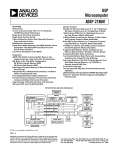
1
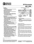
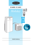
a
Microphone Preamplifier with
Variable Compression and Noise Gating
SSM2166*
20 dB; this gain is in addition to the variable gain in other compression settings. The input buffer can also be configured for frontend gains of 0 dB to 20 dB. A downward expander (noise gate)
prevents amplification of noise or hum. This results in optimized signal levels prior to digitization, thereby eliminating the
need for additional gain or attenuation in the digital domain
that could add noise or impair accuracy of speech recognition
algorithms. The compression ratio and time constants are set
externally. A high degree of flexibility is provided by the VCA
Gain, Rotation Point, and Noise Gate adjustment pins.
FEATURES
Complete Microphone Conditioner in a 14-Lead Package
Single +5 V Operation
Adjustable Noise Gate Threshold
Compression Ratio Set by External Resistor
Automatic Limiting Feature—Prevents ADC Overload
Adjustable Release Time
Low Noise and Distortion
Power-Down Feature
20 kHz Bandwidth (ⴞ1 dB)
Low Cost
The SSM2166 is an ideal companion product for audio codecs
used in computer systems, such as the AD1845 and AD1847.
The device is available in 14-lead SOIC and P-DIP packages,
and guaranteed for operation over the extended industrial temperature range of –40°C to +85°C. For similar features/performance
in an 8-lead package, please refer to the SSM2165.
APPLICATIONS
Microphone Preamplifier/Processor
Computer Sound Cards
Public Address/Paging Systems
Communication Headsets
Telephone Conferencing
Guitar Sustain Effects Generator
Computerized Voice Recognition
Surveillance Systems
Karaoke and DJ Mixers
10
OUTPUT – dBu
–10
GENERAL DESCRIPTION
The SSM2166 integrates a complete and flexible solution for
conditioning microphone inputs in computer audio systems. It
is also excellent for improving vocal clarity in communications
and public address systems. A low noise voltage controlled
amplifier (VCA) provides a gain that is dynamically adjusted by
a control loop to maintain a set compression characteristic. The
compression ratio is set by a single resistor and can be varied
from 1:1 to over 15:1 relative to a user defined “rotation
point;” signals above the rotation point are limited to prevent
overload and eliminate “popping.” In the 1:1 compression setting the SSM2166 can be programmed with a fixed gain of up to
5
BUFOUT
6
3
RATIO = 1:1
–30
–60
–70
–60
VCAR
1kV
V+
2
VCA
11
+
10
25kV
2.3kV
500kV
NOISE GATE
SET
CONTROL
SSM2166
GND
0
VCA GAIN
ADJ
13
VOUT
9
8
AVG
CAP 22mF
–10
14
0.1mF
1
–20
V+
4
1kV
12
–40
–30
INPUT – dBu
10mF*
+
BUFFER
POWER
DOWN
–50
Figure 1. SSM2166 Compression and Gating Characteristics with 10 dB of Fixed Gain (The Gain Adjust Pin Can Be
Used to Vary This Fixed Gain Amount)
LEVEL
DETECTOR
*Patents pending.
–20
–50
VCAIN
7
R2 = 10kV
+
1mF
RATIO = 2:1
–40
10mF
+
R1 = 10kV
AUDIO
+IN
RATIO = 10:1
0
17kV
ROTATION
POINT SET
COMPRESSION
RATIO
SET
*OPTIONAL
Figure 2. Functional Block Diagram and Typical Speech Application
REV. A
Information furnished by Analog Devices is believed to be accurate and
reliable. However, no responsibility is assumed by Analog Devices for its
use, nor for any infringements of patents or other rights of third parties
which may result from its use. No license is granted by implication or
otherwise under any patent or patent rights of Analog Devices.
One Technology Way, P.O. Box 9106, Norwood, MA 02062-9106, U.S.A.
Tel: 781/329-4700
World Wide Web Site: http://www.analog.com
Fax: 781/326-8703
© Analog Devices, Inc., 1999
= +5 V, f = 1 kHz, R = 100 kΩ, R = 600 kΩ, R
= 3 kΩ, R
= 0 Ω,
SSM2166–SPECIFICATIONS (V+
R1 = 0 Ω, R2 = ∞⍀, T = +25ⴗC, unless otherwise noted, V = 300 mV rms.)
L
GATE
ROTATION
A
Parameter
AUDIO SIGNAL PATH
Voltage Noise Density
Noise
Total Harmonic Distortion
Input Impedance
Output Impedance
Load Drive
Symbol
Conditions
en
15:1 Compression
20 kHz Bandwidth, VIN = GND
2nd and 3rd Harmonics, VIN = –20 dBu
22 kHz Low-Pass Filter
THD+N
17
–109
0.25
Max
Units
0.5
nV/√Hz
dBu1
%
2
kΩ
Ω
kΩ
nF
5
1% THD
1% THD
1
1
V rms
V rms
1% THD
1% THD
1:1 Compression, VCA G = 60 dB
1
1.4
30
V rms
V rms
MHz
60
–60 to +19
1:1
15:1
±5
See Figure 5 for RCOMP/RROT
15:1 Compression, Rotation Point = –10 dBu
VS
ISY
4.5
7.5
2.2
50
PSRR
POWER DOWN
Supply Current
Typ
180
75
Resistive
Capacitive
CONTROL SECTION
VCA Dynamic Gain Range
VCA Fixed Gain Range
Compression Ratio, Min
Compression Ratio, Max
Control Feedthrough
POWER SUPPLY
Supply Voltage Range
Supply Current
Quiescent Output Voltage Level
Power Supply Rejection Ratio
Min
ZIN
ZOUT
Buffer
Input Voltage Range
Output Voltage Range
VCA
Input Voltage Range
Output Voltage Range
Gain Bandwidth Product
COMP
IN
Pin 12 = V+2
10
dB
dB
mV
5.5
10
V
mA
V
dB
100
µA
NOTES
1
0 dBu = 0.775 V rms.
2
Normal operation: Pin 12 = 0 V.
Specifications subject to change without notice.
ORDERING GUIDE
ABSOLUTE MAXIMUM RATINGS
Supply Voltage . . . . . . . . . . . . . . . . . . . . . . . . . . . . . . . . . +10 V
Audio Input Voltage . . . . . . . . . . . . . . . . . . . . . Supply Voltage
Operating Temperature Range . . . . . . . . . . . . –40°C to +85°C
Storage Temperature Range . . . . . . . . . . . . . –65°C to +150°C
Junction Temperature (TJ ) . . . . . . . . . . . . . . . . . . . . . +150°C
Lead Temperature (Soldering, 60 sec) . . . . . . . . . . . . +300°C
Model
Temperature
Range
Package
Description
Package
Option
SSM2166P
SSM2166S
–40°C to +85°C
–40°C to +85°C
Plastic DIP
Narrow SOIC
N-14
SO-14
ESD RATINGS
883 (Human Body) Model . . . . . . . . . . . . . . . . . . . . . . 2.0 kV
THERMAL CHARACTERISTICS
Thermal Resistance
14-Lead Plastic DIP
θ JA . . . . . . . . . . . . . . . . . . . . . . . . . . . . . . . . . . . . 83°C/W
θ JC . . . . . . . . . . . . . . . . . . . . . . . . . . . . . . . . . . . . 39°C/W
14-Lead SOIC
θ JA . . . . . . . . . . . . . . . . . . . . . . . . . . . . . . . . . . . 120°C/W
θ JC . . . . . . . . . . . . . . . . . . . . . . . . . . . . . . . . . . . . 36°C/W
CAUTION
ESD (electrostatic discharge) sensitive device. Electrostatic charges as high as 4000 V readily
accumulate on the human body and test equipment and can discharge without detection.
Although the SSM2166 features proprietary ESD protection circuitry, permanent damage may
occur on devices subjected to high energy electrostatic discharges. Therefore, proper ESD
precautions are recommended to avoid performance degradation or loss of functionality.
–2–
WARNING!
ESD SENSITIVE DEVICE
REV. A
SSM2166
PIN DESCRIPTION
Pin #
Mnemonic
Function
1
2
GND
GAIN ADJUST
Ground
VCA Gain Adjust Pin. A resistor from this pin to ground sets the fixed gain of the VCA. To
check the setting of this pin the compression pin (Pin 10) should be grounded for no compression. The gain can be varied from 0 dB to 20 dB. For 20 dB leave the pin open. For
0 dB of fixed gain, a typical resistor value is approximately 1 kΩ. For 10 dB of fixed gain, the
resistor value is approximately 2 kΩ–3␣ kΩ. For resistor values < 1 kΩ, the VCA can attenuate or mute. Refer to Figure 6.
3
VCAIN
VCA Input Pin. A typical connection is a 10 µF capacitor from the buffer output pin (Pin 5)
to this pin.
4
VCAR
Inverting Input to the VCA. This input can be used as a nonground reference for the audio
input signal (see application notes).
5
BUF OUT
Input Buffer Amplifier Output Pin. Must not be loaded by capacitance to ground.
6
–IN
Inverting Input to the Buffer. A 10 kΩ feedback resistor R1 from the buffer output Pin 5 to
this input pin, and a resistor R2, from this pin through a 1 µF to ground gives gains of 6 dB
to 20 dB for R2 = 10 kΩ to 1.1 kΩ.
7
AUDIO +IN
Input Audio Signal. The input signal should be ac-coupled (0.1 µF typical) into this pin.
8
AVG CAP
Detector Averaging Capacitor. A capacitor, 2.2 µF–22 µF, to ground from this pin is the
averaging capacitor for the detector circuit.
9
NOISE GATE SET
Noise Gate Threshold Set Point. A resistor to V+ sets the level below which input signals are
downward-expanded. For a 0.7 mV threshold, the resistor value is approximately 380 kΩ.
Increasing the resistor value reduces the threshold. See Figure 4.
10
COMP RATIO SET
Compression Ratio Set Pin. A resistor to ground from this pin sets the compression ratio as
shown in Figure 1. Figure 5 gives resistor values for various rotation points.
11
ROTATION SET
Rotation Point Set Pin. This is set by a resistor to the positive supply. This resistor together
with the gain adjust pin determines the onset of limiting. A typical value for this resistor is
17K for a 100 mV “rotation point.” Increasing the resistor value reduces the level at which
limiting occurs. Refer to Figure 9.
12
POWER DOWN
Power-Down Pin. Connect to ground for normal operation. Connect to positive supply for
power-down mode.
13
OUTPUT
Output Signal.
14
V+
Positive Supply, +5 V Nominal.
PIN CONFIGURATION
14 V+
GND 1
13 OUTPUT
GAIN ADJUST 2
VCAIN 3
SSM2166
12 POWER DOWN
TOP VIEW 11 ROTATION SET
BUF OUT 5 (Not to Scale) 10 COMP RATIO SET
VCAR 4
–IN 6
9 NOISE GATE SET
8 AVG CAP
AUDIO +IN 7
REV. A
–3–
SSM2166
20
0
COMP RATIO = 15:1
COMP RATIO = 10:1
COMP RATIO = 5:1
–10
18
16
14
–30
GAIN – dB
OUTPUT – dBu
–20
COMP RATIO = 2:1
–40
–50
–60
–70
COMP RATIO = 1:1
TA = +25°C
V+ = 5V
VIN = 300mV rms @ 1kHz
RL = 100kV
NOISE GATE SETTING 550µV rms
ROTATION POINT 300mV rms
GAIN ADJUST (PIN 2) = 1.25kV
–70
–60
–50
–40
–30
INPUT – dBu
–20
–10
TA = +25°C
V+ = 5V
RL = 100kV
VIN = 100mV rms @ 1kHz
NOISE GATE SETTING 550mV rms
ROTATION POINT (PIN 11) 1V rms
COMPRESSION RATIO = 1:1
10
8
6
4
2
0
–80
–80
0
0
2
4
6
8 10 12 14 16 18 20 22 24
GAIN ADJUST RESISTOR – kV
26 28
30
Figure 6. VCA Gain vs. RGAIN (Pin 2 to GND)
Figure 3. Output vs. Input Characteristics
5
100
TA = +25°C
V+ = 5V
RL = 100kV
COMPRESSION RATIO = 2:1
ROTATION POINT 1V rms
GAIN ADJUST (PIN 2) = 1.25kV
10
TA = +25°C
V+ = 5V
COMPRESSION RATIO = 1:1
NOISE GATE SETTING 550mV rms
ROTATION POINT 1V rms
GAIN ADJUST (PIN 2) = 1.25kV
VIN FREQUENCY = 1kHz
1
THD + N – %
NOISE GATE – mV rms
12
RL = 10kV
1
RL = 100kV
0.1
0.1
0
0.05
0.01
50 100 150 200 250 300 350 400 450 500 550 600 650
0.1
INPUT VOLTAGE – V rms
RGATE – kV
1
Figure 7. THD+N (%) vs. Input (V rms)
Figure 4. Noise Gate vs. RGATE (Pin 9 to V+)
5
COMPRESSION
RATIO
1
1:1
2:1
5:1
10:1
15:1
100mV rms
0
12.5
96
215
395
300mV rms
0
12.5
96
215
395
1V rms
0
12.5
96
215
395
THD + N – %
ROTATION POINT
TA = +25°C
V+ = 5V
VIN = 77.5mV rms @ 1kHz
COMPRESSION RATIO = 1:1
NOISE GATE SETTING 550mV rms
ROTATION POINT 1V rms
GAIN ADJUST (PIN 2) = 1.2kV
MEASUREMENT FILTER BW : 22Hz TO 30kHz
0.1
RCOMP – kV, TYPICAL
0.05
20
100
1k
FREQUENCY – Hz
10k
30k
Figure 8. THD+N (%) vs. Frequency (Hz)
Figure 5. Compression Ratio vs. R COMP (Pin 10 to GND)
–4–
REV. A
SSM2166
1.0
–10
TA = +25°C
V+ = 5V
RL = 100kV
–20
–30
PSRR – dB
ROTATION POINT – V rms
COMPRESSION RATIO = 1:1
NOISE GATE SETTING 550mV rms
GAIN ADJUST (PIN 2) = 1.25kV
RCOMP = 0
RGAIN = 1.24kV
RGATE = 500kV
RROT = 1.74kV
0.1
V+ = 5±1V p-p
–40
–50
V+ = 5±0.5V p-p
–60
–70
0.01
0
–80
20
5 10 15 20 25 30 35 40 45 50 55 60 65 70 75 80 85 90
100
RROT PT RESISTOR – kV
10k
30k
Figure 10c. PSRR vs. Frequency
Figure 9. Rotation Point vs. RROT PT (Pin 11 to V+)
5mV
1k
FREQUENCY – Hz
20mV
1s
100
90
100
90
TA = +25 C
CAVG = 2.2mF
10
0%
10
TA = +25 C
COMPRESSION RATIO = 15:1
NOISE BW = 20kHz
0%
SYSTEM GAIN = 0dB
RL = 10kV
COMP RATIO = 1:1
10ms
Figure 11. Small Signal Transient Response
Figure 10a. Wideband Output Noise
70
G = 60dB
60
200mV
50
G = 40dB
100
90
GAIN – dB
40
30
G = 20dB
20
10
10
ROTATION POINT = 1.13V rms
NOISE GATE SETTING = 336mV rms
RCOMP = 40kV
VIN = 400mV rms
0
–10
–20
1k
10k
100k
FREQUENCY – Hz
0%
10ms
1M
Figure 10b. GBW Curves vs. VCA Gain
REV. A
TA = +25 C
CAVG = 2.2mF
SYSTEM GAIN = 0dB
RL = 10kV
COMP RATIO = 1:1
Figure 12. Large Signal Transient Response
–5–
SSM2166
APPLICATIONS INFORMATION
The SSM2166 contains an input buffer and automatic gain control (AGC) circuit for audio- and voiceband signals. Circuit
operation is optimized by providing a user-adjustable time constant and compression ratio. A downward expansion (noise gating) feature eliminates circuit noise in the absence of an input
signal. The SSM2166 allows the user to set the downward expansion threshold, the limiting threshold (rotation point), input
buffer fixed gain, and the internal VCA’s nominal gain at the rotation point. The SSM2166 also features a power-down mode
and muting capability.
Theory of Operation
Figure 13 illustrates a typical transfer characteristic for the
SSM2166 where the output level in dB is plotted as a function of the input level in dB. The dotted line indicates the
transfer characteristic for a unity-gain amplifier. For input
signals in the range of VDE (Downward Expansion) to VRP
(Rotation Point) an “r” dB change in the input level causes a
1 dB change in the output level. Here, “r” is defined as the
“compression ratio.” The compression ratio may be varied
from 1:1 (no compression) to over 15:1 via a single resistor,
RCOMP. Input signals above VRP are compressed with a fixed
compression ratio of approximately 15:1. This region of operation is the “limiting region.” Varying the compression ratio has
no effect on the limiting region. The breakpoint between the
compression region and the limiting region is referred to as the
“limiting threshold” or the “rotation point,” and is user-specified
in the SSM2166. The term “rotation point” derives from the
observation that the straight line in the compression region
“rotates” about this point on the input/output characteristic as
the compression ratio is changed.
LIMITING
THRESHOLD
(ROTATION POINT)
OUTPUT – dB
The SSM2166 is a complete microphone signal conditioning
system on a single integrated circuit. Designed primarily for
voiceband applications, this integrated circuit provides amplification, rms detection, limiting, variable compression, and downward expansion. An integral voltage-controlled amplifier (VCA)
provides up to 60 dB of gain in the signal path with approximately 30 kHz bandwidth. Additional gain is provided by an
input buffer op amp circuit that can be set anywhere from 0 dB
to 20 dB, for a total signal path gain of up to 80 dB. The device
operates on a single +5 V supply, accepts input signals up to
1 V rms, and produces output signal levels > 1 V rms (3 V p-p)
into loads > 5 kΩ. The internal rms detector has a time constant set by an external capacitor.
LIMITING
REGION
DOWNWARD COMPRESSION
REGION
EXPANSION
THRESHOLD
1
(NOISE GATE)
r
VCA GAIN
DOWNWARD
EXPANSION
REGION
1
1
VDE
VRP
INPUT – dB
Figure 13. General Input/Output Characteristics of the
SSM2166
The SSM2166 Signal Path
Figure 14 illustrates the block diagram of the SSM2166. The
audio input signal is processed by the input buffer and then
by the VCA. The input buffer presents an input impedance
of approximately 180 kΩ to the source. A dc voltage of approximately 1.5 V is present at AUDIO +IN (Pin 7 of the SSM2166),
requiring the use of a blocking capacitor (C1) for groundreferenced sources. A 0.1 µF capacitor is a good choice for most
audio applications. The input buffer is a unity-gain stable amplifier that can drive the low impedance input of the VCA.
The VCA is a low distortion, variable-gain amplifier whose gain
is set by the side-chain control circuitry. The input to the VCA
is a virtual ground in series with approximately 1 kΩ. An external blocking capacitor (C6) must be used between the buffer’s
output and the VCA input. The 1 kΩ impedance between amplifiers determines the value of this capacitor which is typically
between 4.7 µF and 10 µF. An aluminum electrolytic capacitor
is an economical choice. The VCA amplifies the input signal
current flowing through C6 and converts this current to a voltage at the SSM2166’s output pin (Pin 13). The net gain from
input to output can be as high as 60 dB (without additional
buffer gain), depending on the gain set by the control circuitry.
The gain of the VCA at the rotation point is set by the value of a
resistor connected between Pin 2 and GND, RGAIN. The relationship between the VCA gain and RGAIN is shown in Figure 6.
The AGC range of the SSM2166 can be as high as 60 dB. The
VCAIN pin (Pin 3) on the SSM2166 is the noninverting input
terminal to the VCA. The inverting input of the VCA is also
available on the SSM2166’s Pin 4 (VCAR) and exhibits an input
impedance of 1 kΩ, as well. As a result, this pin can be used for
differential inputs or for the elimination of grounding problems
by connecting a capacitor whose value equals that used in series
with the VCAIN pin, to ground. See Figure 22, SSM2166
Evaluation Board for more details.
The gain of the system with an input signal level of VRP is fixed
by RGAIN regardless of the compression ratio, and is the “nominal gain” of the system. The nominal gain of the system may be
increased by the user via the onboard VCA by up to 20 dB. Additionally, the input buffer of the SSM2166 can be configured
to provide fixed gains of 0 dB to 20 dB with R1 and R2.
Input signals below VDE are downward expanded; that is, a –1 dB
change in the input signal level causes approximately a –3 dB
change in the output level. As a result, the gain of the system is
small for very small input signal levels, even though it may be
quite large for small input signals above of VDE. The downward
expansion threshold, VDE , is set externally by the user via RGATE
at Pin 9 (NOISE GATE). Finally, the SSM2166 provides an
active HIGH, CMOS-compatible digital input whereby a
power-down feature will reduce device supply current to less
than 100 µA.
The output impedance of the SSM2166 is typically less that
75 Ω, and the external load on Pin 13 should be >5 kΩ. The
nominal output dc voltage of the device is approximately 2.2 V.
Use a blocking capacitor for grounded loads.
The bandwidth of the SSM2166 is quite wide at all gain settings. The upper 3 dB point is approximately 30 kHz at gains as
high as 60 dB (using the input buffer for additional gain, circuit
–6–
REV. A
SSM2166
C7*
10mF
C6
10mF
V+
5
3
BUFOUT
VCAIN
VCAR
1kV
1kV
14
R1 = 10kV
INPUT
BUFFER
4
OUTPUT 13
AUDIO
+IN
VOUT
VCA
7
GAIN
ADJUST
0.1mF
2
SSM2166
R2 = 10kV
+
1mF
RMS
LEVEL
DETECTOR
CONTROL
CIRCUITRY
NOISE
GATE
AVG
CAP
1
8
RGATE
9
ROTATION
POINT
ADJUST 11
POWER
DOWN
GND
V+
RGAIN
12
COMPRESSION
RATIO SET
RROT PT
POWER
DOWN
10
CAVG
2.2mF
*OPTIONAL
RCOMP
GND
Figure 14. Functional Block Diagram and Typical Application
bandwidth is unaffected). The GBW plots are shown in Figure
10b. The lower 3 dB cutoff frequency of the SSM2166 is set by
the input impedance of the VCA (1 kΩ) and C6. While the
noise of the input buffer is fixed, the input referred noise of the
VCA is a function of gain. The VCA input noise is designed to
be a minimum when the gain is at a maximum, thereby optimizing the usable dynamic range of the part. A photograph of the
SSM2166’s wideband peak-to-peak output noise is illustrated in
Figure 10b.
The Level Detector
The SSM2166 incorporates a full-wave rectifier and a patentpending, true rms level detector circuit whose averaging time
constant is set by an external capacitor connected to the AVG
CAP pin (Pin 8). For optimal low frequency operation of the
level detector down to 10 Hz, the value of the capacitor should
be 2.2 µF. Some experimentation with larger values for the
AVG CAP may be necessary to reduce the effects of excessive
low frequency ambient background noise. The value of the averaging capacitor affects sound quality: too small a value for this
capacitor may cause a “pumping effect” for some signals, while
too large a value can result in slow response times to signal dynamics. Electrolytic capacitors are recommended here for lowest cost and should be in the range of 2 µF to 47 µF. Capacitor
values from 18 µF to 22 µF have been found to be more appropriate in voiceband applications, where capacitors on the low
end of the range seem more appropriate for music program
material.
The rms detector filter time constant is approximately given by
10•CAVG milliseconds where CAVG is in µF. This time constant
controls both the steady-state averaging in the rms detector as
well as the release time for compression; that is, the time it takes
for the system gain to react when a large input is followed by a
REV. A
–7–
small signal. The attack time, the time it takes for the gain to be
reduced when a small signal is followed by a large signal, is controlled partly by the AVG CAP value, but is mainly controlled
by internal circuitry that speeds up the attack for large level
changes. This limits overload time to under 1 ms in most cases.
The performance of the rms level detector is illustrated in Figure 15 for a CAVG of 2.2 µF (Figure 15a) and 22 µF (Figure
15b). In each of these photographs, the input signal to the
SSM2166 (not shown) is a series of tone bursts in 6 successive
10 dB steps. The tone bursts range from –66 dBV (0.5 mV rms)
to –6 dBV (0.5 V rms). As illustrated in the photographs, the
attack time of the rms level detector is dependent only on CAVG,
but the release times are linear ramps whose decay times are
dependent on both CAVG and the input signal step size. The
rate of release is approximately 240 dB/s for a CAVG of 2.2 µF,
and 12 dB/s for a CAVG of 22 µF.
100mV
100
90
6dBV
66dBV
10
85dBV
0%
100ms
Figure 15a. RMS Level Detector Performance with
CAVG = 2.2 µ F
SSM2166
the rotation point may be varied from approximately 20 mV rms
to 1 V rms. From the figure, the rotation point is inversely proportional to RROT PT. For example, a 1 kΩ resistor would typically
set the rotation point at 1 V rms, whereas a 55 kΩ resistor would
typically set the rotation point at approximately 30 mV rms.
1S
100mV
100
90
6dBV
Since limiting occurs for signals larger than the rotation point
(VIN > VRP), the rotation point effectively sets the maximum
output signal level. It is recommended that the rotation point
be set at the upper extreme of the range of typical input signals
so that the compression region will cover the entire desired input signal range. Occasional larger signal transients will then be
attenuated by the action of the limiter.
66dBV
10
85dBV
0%
Figure 15b. RMS Level Detector Performance with
CAVG = 22 µ F
Control Circuitry
Compression Ratio. Changing the scaling of the control signal fed to the VCA causes a change in the circuit’s compression
ratio, “r.” This effect is shown in Figure 16. The compression
ratio can be set by connecting a resistor between the COMP
RATIO pin (Pin 10) and GND. Lowering RCOMP gives smaller
compression ratios as indicated in Figure 5, with values of about
17 kΩ or less resulting in a compression ratio of 1:1. AGC performance is achieved with compression ratios between 2:1 and
15:1, and is dependent on the application. A 100 kΩ potentiometer may be used to allow this parameter to be adjusted. On the
evaluation board (Figure 22), an optional resistor can be used to
set the compression equal to 1:1 when the wiper of the potentiometer is at its full CCW position.
15:1
5:1
VCA GAIN
1
1
VDE
VRP1 VRP2 VRP3
INPUT – dB
Figure 17. Effect of Varying the Rotation Point
VCA Gain Setting and Muting. The maximum gain of the
SSM2166 is set by the GAIN ADJUST pin (Pin 2) via RGAIN.
This resistor, with a range between 1 kΩ and 20 kΩ, will cause
the nominal VCA gain to vary from 0 dB to approximately
20 dB, respectively. To set the VCA gain to its maximum can
also be achieved by leaving the GAIN ADJUST pin in an
OPEN condition (no connect). Figure 18 illustrates the effect
on the transfer characteristic by varying this parameter. For low
level signal sources, the VCA should be set to maximum gain
using a 20 kΩ resistor.
VCA GAIN
2:1
OUTPUT – dB
r:1
OUTPUT – dB
The output of the rms level detector is a signal proportional to
the log of the true rms value of the buffer output with an added
dc offset. The control circuitry subtracts a dc voltage from this
signal, scales it, and sends the result to the VCA to control the
gain. The VCA’s gain control is logarithmic—a linear change in
control signal causes a dB change in gain. It is this control law
that allows linear processing of the log rms signal to provide the
flat compression characteristic on the input/output characteristic
shown in Figure 13.
1:1
OUTPUT – dB
r:1
1
1
VDE
INPUT – dB
VCA GAIN
VRP
1
1
Figure 16. Effect of Varying the Compression Ratio
VDE
Rotation Point. An internal dc reference voltage in the control
circuitry, used to set the rotation point, is user-specified, as illustrated in Figure 9. The effect on rotation point is shown in
Figure 17. By varying a resistor, RROT PT, connected between the
positive supply and the ROTATION POINT SET pin (Pin 11),
INPUT – dB
VRP
Figure 18. Effect of Varying the VCA Gain Setting
–8–
REV. A
SSM2166
The gain of the VCA can be reduced below 0 dB by making
RGAIN smaller than 1 kΩ. Switching Pin 2 through 330 Ω or less
to ground will mute the output. Either a switch connected to
ground or a transistor may be used, as shown in Figure 19. To
avoid audible “clicks” when using this MUTE feature, a capacitor (C5 in figure) can be connected from pin 2 to GND. The
value of the capacitor is arbitrary and should be determined empirically, but a 0.01 µF capacitor is a good starting value.
SSM2166
GAIN
ADJUST
2
330V
C5
RGAIN
MUTE
(CLOSED SWITCH)
Power-Down Feature
The supply current of the SSM2166 can reduced to under
100 µA by applying an active HIGH, 5 V CMOS compatible
input to the SSM2166’s POWER DOWN pin (Pin 12). In this
state, the input and output circuitry of the SSM2166 will assume a
high impedance state; as such, the potentials at the input pin
and the output pin will be determined by the external circuitry
connected to the SSM2166. The SSM2166 takes approximately
200 ms to settle from a POWER-DOWN to POWER-ON command. For POWER-ON to POWER-DOWN, the SSM2166
requires more time, typically less than 1 s. Cycling the power
supply to the SSM2166 can result in quicker settling times: the
off-to-on settling time of the SSM2166 is less than 200 ms,
while the on-to-off settling time is less than 1 ms. In either
implementation, transients may appear at the output of the device. In order to avoid these output transients, MUTE control
of the VCA’s gain as previously mentioned should be used.
PC Board Layout Considerations
NOTE: ADDITIONAL CIRCUIT DETAILS
OMITTED FOR CLARITY.
Figure 19. Details of SSM2166 Mute Option
Downward Expansion Threshold. The downward expansion, or noise gate, threshold is determined via a second reference voltage internal to the control circuitry. This second
reference can be varied in the SSM2166 using a resistor, RGATE,
connected between the positive supply and the NOISE GATE
SET pin (Pin 9) of the SSM2166. The effect of varying this
threshold is shown in Figure 20. The downward expansion
threshold may be set between 300 µV rms and 20 mV rms by
varying the resistance value between Pin 9 and the supply voltage. Like the ROTATION PT ADJUST, the downward expansion threshold is inversely proportional to the value of this
resistance: setting this resistance to 1 MΩ sets the threshold at
approximately 250 µV rms, whereas a 10 kΩ resistance sets the
threshold at approximately 20 mV rms. This relationship is
illustrated in Figure 4. A potentiometer network is provided on
the evaluation board for this adjustment. In general, the downward expansion threshold should be set at the lower extreme of
the desired range of the input signals, so that signals below this
level will be attenuated.
OUTPUT – dB
VCA GAIN
1
1
INPUT – dB
VRP
Figure 20. Effect of Varying the Downward Expansion
(Noise Gate) Threshold
REV. A
(1) In some high system gain applications, the shielding of input wires to minimize possible feedback from the output of the
SSM2166 back to the input circuit may be necessary.
(2) A single-point (“star”) ground implementation is recommended in addition to maintaining short lead lengths and PC
board runs. The evaluation board layout shown in Figure 23 for
the SSM2166 demonstrates the single-point grounding scheme.
In applications where an analog ground and a digital ground are
available, the SSM2166 and its surrounding circuitry should be
connected to the system’s analog ground. As a result of these
recommendations, wire-wrap board connections and grounding
implementations are to be explicitly avoided.
(3) The internal buffer of the SSM2166 was designed to drive
only the input of the internal VCA and its own feedback network. Stray capacitive loading to ground from the BUFOUT pin
in excess of 5 pF to 10 pF can cause excessive phase shift and
can lead to circuit instability.
(4) When using high impedance sources (≥ 5 kΩ), system gains
in excess of 60 dB are not recommended. This configuration is
rarely appropriate, as virtually all high impedance inputs provide
larger amplitude signals that do not require as much amplification. When using high impedance sources, however, it can be
advantageous to shunt the source with a capacitor to ground at
the input pin of the IC (Pin 7) to lower the source impedance at
high frequencies, as shown in Figure 21. A capacitor with a value
of 1000 pF is a good starting value and sets a low pass corner at
31 kHz for 5 kΩ sources. In those applications where the source
ground is not as “clean” as would be desirable, a capacitor (illustrated as C7 on the evaluation board) from the VCAR input to
the source ground might prove beneficial. This capacitor is
used in addition to the grounded capacitor (illustrated as C2 on
the evaluation board) used in the feedback around the buffer,
assuming that the buffer is configured for gain.
r:1
VDE2
VDE1 VDE3
Since the SSM2166 is capable of wide bandwidth operation and
can be configured for as much as 80 dB of gain, special care
must be exercised in the layout of the PC board which contains
the IC and its associated components. The following applications hints should be considered and/or followed:
–9–
SSM2166
C1
0.1mF
AUDIO IN
(RS > 5kV)
7
The value of the C7 should be the same as C6, the capacitor
value used between BUFOUT and VCAIN. This connection makes
the source ground noise appear as a common-mode signal to the
VCA, allowing the common-mode noise to be rejected by the
VCA’s differential input circuitry. C7 can also be useful in
reducing ground loop problems and in reducing noise coupling
from the power supply by balancing the impedances connected
to the inputs of the internal VCA.
+IN
CX
1000pF
SSM2166
NOTE: ADDITIONAL CIRCUIT DETAILS
OMITTED FOR CLARITY.
SSM2166 Evaluation Board
A schematic diagram of the SSM2166 evaluation board, available upon request from Analog Devices, is illustrated in Figure
22. As a design aid, the layouts for the topside silkscreen,
topside and backside metallization layers are shown in Figures
23a, b, and c. Although not shown to scale, the finished dimension of the evaluation board is 3.5 inches by 3.5 inches, and
comes complete with pin sockets and a sample of the SSM2166.
Figure 21. Circuit Configuration for Use with High
Impedance Signal Sources
+V
C6
10mF
+
R1
10kV
R4
1kV
5
3
R2
10kV
R12
100kV
R8
1kV
CW
14
ROT PT.
ADJ
9
NOISE
GATE
ADJ
V+
+INPUT
VCAR
AVG
CAP
4
8
C1
0.1mF
MIC
PWR
INPUT
JACK
1/8"
PHONE
POWER
DN
1
C7
10mF
GND
COMP
RATIO
GAIN
ADJUST
2
+ C4
22mF
R9
1kV
10
R11
330V
3
R10
20kV
GAIN CW
ADJ
OUTPUT
13
5
C5
0.01mF
COMP
RATIO
1
2
+
J3
12
SSM2166
–INPUT
7
C2
1mF
NOISE
GATE
R7
1MV
CW
11
VCAIN
BUFOUT
6
ROTATION
PT ADJ
R3
50kV
C3
0.1mF
MUTE
SWITCH
4
OP113
R6
100kV
CW
6
7
OUTPUT
JACK
RCA
PHONO
Figure 22. Evaluation Board
–10–
REV. A
SSM2166
Figure 23a. Evaluation Board Topside Silkscreen
(Not to Scale)
Figure 23c. Evaluation Board Backside Metallization
(Not to Scale)
Signal sources are connected to the SSM2166 through a 1/8"
phone jack where a 0.1 µF capacitor couples the input signal to
the SSM2166’s +IN pin (Pin 7). As shown in Figure 22 and in
microphone applications, the phone jack shield can be optionally
connected to the board’s ground plane (Jumper J1 inserted into
board socket pins labeled “1” and “2”) or to the SSM2166’s
VCAR input at Pin 4 (Jumper J1 inserted into board socket pins
labeled “1” and “3”). If the signal source is a waveform or
function generator, the phone jack shield is to be connected
to ground.
For ease in making adjustments for all of the SSM2166’s configuration parameters, single-turn potentiometers are used
throughout. Optional Jumper J2 connects the COMP RATIO
pin to ground and sets the SSM2166 for no compression (that
is, compression ratio = 1:1). Optional Jumper J3 connects the
SSM2166’s POWER DOWN input to ground for normal operation. Jumper J3 can be replaced by an open-drain logic buffer
for a digitally-controlled shutdown function. An output signal
MUTE function can be implemented on the SSM2166 by connecting the GAIN ADJUST pin (Pin 2) through a 330 Ω resistance to ground. This is provided on the evaluation board via
R11 and S1. A capacitor C5, connected between Pin 2 and
ground and provided on the evaluation board, can be used to
avoid audible “clicks” when using the MUTE function.
Figure 23b. Evaluation Board Topside Metallization
(Not to Scale)
To configure the SSM2166’s input buffer for gain, provisions for
R1, R2, and C2 have been included. To configure the input
buffer for unity-gain operation, R1 and R2 are removed, and a
direct connection is made between the –IN pin (Pin 6) and the
BUFOUT pin (Pin 5) of the SSM2166.
The output stage of the SSM2166 is capable of driving > 1 V
rms (3 V p-p) into > 5 kΩ loads, and is externally available
through an RCA phono jack provided on the board. If the output of the SSM2166 is required to drive a lower load resistance
REV. A
–11–
SSM2166
or an audio cable, then the onboard OP113 can be used. To
use the OP113 buffer, insert Jumper J4 into board socket pins
labeled “4” and “5” and insert Jumper J5 into board socket pins
labeled “6” and “7.” If the output buffer is not required, remove Jumper J5 and insert Jumper J4 into board socket pins “5”
and “7.” There are no blocking capacitors either on the input
nor at the output of the buffer. As a result, the output dc level
of the buffer will match the output dc level of the SSM2166,
which is approximately 2.3 V. A dc blocking capacitor may be
inserted on Pins 6 and 7. An evaluation board and setup procedure is available from your Analog Devices representative.
Setup Procedure with Evaluation Board
To illustrate how easy it is to program the SSM2166, we will
take a practical example. The SSM2166 will be used interface
an electret-type microphone to a post-amplifier. You can use
the evaluation board or the circuit configuration shown in Figure
22. The signal from the microphone was measured under actual
conditions to vary from 1 mV to 15 mV. The post-amplifier
requires no more than 500 mV at its input. The required gain
from the SSM2166 is, therefore:
Evaluation Board
If you build your own breadboard, keep the leads to Pins 3, 4,
and 5 short. A convenient evaluation board is available from
your sales representative. The R and C designations refer to the
demonstration board schematic of Figure 22 and parts list,
Figure 28.
Test Equipment Setup
The recommended equipment and configuration is shown in
Figure 26. A low noise audio generator with a smooth output
adjustment range of 50 µV to 50 mV is a suitable signal source.
A 40 dB pad would be useful to reduce the level of most generators by 100× to simulate the microphone levels. The input voltmeter could be connected before the pad, and need only go
down to 10 mV. The output voltmeter should go up to 2 volts.
The oscilloscope is used to verify that the output is sinusoidal,
that no clipping is occurring in the buffer, and to set the limiting
and noise gating “knees.”
SSM2166
EVALUATION
BOARD
SIGNAL
GENERATOR
GTOT = 20 × log (500/15) = 30 dB
We will set the input buffer gain to 20 dB and adjust the VCA
gain to 10 dB. The limiting or “rotation” point will be set at
500 mV output. From prior experience, we will start with a 2:1
compression ratio, and a noise gate threshold that operates below 100 µV. These objectives are summarized in Figure 24, and
we will fine-tune them later on. The transfer characteristic we
will implement is illustrated in Figure 25.
INPUT RANGE
OUTPUT RANGE
LIMITING LEVEL
COMPRESSION
BUFFER GAIN
VCA GAIN
NOISE GATE
1-15 mV
TO 500 mV
500 mV
2:1
20 dB
10 dB
100 mV
Figure 24. Objective Specifications
ROTATION POINT
OUTPUT – mV
COMPRESSION
REGION
1
AC
VOLTMETER
AC
VOLTMETER
Figure 26. Test Equipment Setup
STEP 1. Configure the Buffer
The SSM2166 has an input buffer that may be used when the
overall gain required exceeds 20 dB, the maximum userselectable gain of the VCA. In our example, the desired output
is 500 mV for an input around 15 mV, requiring a total gain of
30 dB. We will set the buffer gain at 20 dB, and adjust VCA
for 10 dB. In the socket pins provided on the evaluation board,
Insert R1 = 100 kΩ, and R2 = 11 kΩ. You have set the buffer
gain to 20 dB (×10).
STEP 2. Initialize Potentiometers
Note: the SSM2166 processes the output of the buffer, which in
our example is 20 dB or ten times the input level. Use the oscilloscope to verify that you are not driving the buffer into clipping
with excessive input signals. In your application, you should
take the minimum gain in the buffer consistent with the average
source level as well as the crest factor (ratio of peak to rms).
500
OSCILLOSCOPE
LIMITING REGION
With power off, preset the potentiometers per the table of Figure 27 below.
FUNCTION
INITIAL
INITIAL
POT RANGE POSITION RESISTANCE
EFFECT OF CHANGE
GAIN ADJUST
(VCA)
R10 0–20 kV
CCW
ZERO
0 dB; CW TO INCREASE
VCA GAIN
ROTATION
POINT
R3
0–50 kV
CCW
ZERO
1 V; CW TO REDUCE
ROTATION POINT
COMPRESSION
RATIO
R6
0–100
kV
CCW
ZERO
1:1; CW TO INCREASE
COMPRESSION
NOISE GATE
R7
0–1 MV
CW
1 MV
300 mV; CCW TO
INCREASE THRESHOLD
Figure 27. Initial Potentiometer Settings
2
STEP 3. Test Setup
40
With power on, adjust the generator for an input level of 15 mV,
1 kHz. The output meter should indicate approximately 100 mV.
If not, check your setup.
GATE THRESHOLD
STEP 4. Adjusting the VCA Gain
0.1
1.0
Set the input level to 15 mV. Adjust R10—GAIN ADJ CW for
an output level of 500 mV. You have now set the VCA gain to
10 dB.
15
10
INPUT – mV
Figure 25. Transfer Characteristic
–12–
REV. A
SSM2166
STEP 5. Adjusting the Rotation Point
STEP 9. Record Values
Set the input level to 15 mV, and observe the output on the oscilloscope. Adjust R3—ROTATION PT ADJ CW until the
output level just begins to drop, then reverse so that the output is
500 mV. You have now set the limiting to 500 mV.
With the power removed from the test fixture, measure and
record the values of all potentiometers, including any fixed resistance in series with them. If you have changed the averaging
capacitor, C4, note its value too.
STEP 6. Adjusting the Compression Ratio
Set the input signal for an output of 500 mV but not in limiting.
Note the value (around 15 mV). Next, reduce the input to 1/10
the value noted, (around 1.5 mV), for a change of –20 dB. Next,
adjust R6—COMP RATIO CW until the output is 160 mV, for
an output change of –10 dB. You have now set the compression,
which is the ratio of output change to input change, in dB, to 2:1.
SUMMARY
With the input set at 100 µV, observe the output on the oscilloscope, and adjust R7—ROT PT SET CCW until the output
drops rapidly. “Rock” the control back and forth to find the
“knee.” You have set the noise gate to 100 µV. The range of
the noise gate is from 0.3 mV to over 0.5 mV relative to the output of the buffer. To fit this range to your application, you may
have to attenuate the input or apportion the buffer gain and VCA
gain differently.
We have implemented the transfer condition of Figure 2. For
inputs below the 100 µV noise gate threshold, circuit and background noise will be minimized. Above it, the output will increase at a rate of 1 dB for each 2 dB input increase, until the
500 mV rotation point is reached at an input of approximately
15 mV. For higher inputs that would drive the output beyond
500 mV, limiting will occur, and there will be little further increase. The SSM2166 processes the output of the buffer, which
in our example is 20 dB or ten times the input level. Use the oscilloscope to ensure that you are not driving the buffer into clipping with the highest expected input peaks. Always take the
minimum gain in the buffer consistent with the average source
level and crest factor (ratio of peak to rms). The wide program
range of the SSM2166 makes it useful in many applications
other than microphone signal conditioning.
STEP 8. Listening
Other Versions
At this time, you may want to connect an electret microphone to
the SSM2166, and listen to the results. Be sure to include the
proper power for the microphone’s internal FET (usually +2 V
to +5 V dc through a 2.2 kΩ resistor). Experiment with the
settings to hear how the results change. Varying the averaging
capacitor, C4, changes the attack and decay times, which are
best determined empirically. Compression ratio will keep the
output steady over a range of microphone to speaker distance,
and the noise gate will keep the background sounds subdued.
The SSM2165 is an 8-lead version of this microphone preamp
with unity buffer gain and preset noise gate threshold. Customized parts are available for large volume users. For further information, contact your sales representative.
STEP 7. Setting the Noise Gate
REV. A
–13–
SSM2166
SSM2166 Demo Board Parts List
R1
R2
R3
R4
R5
R6
R7
R8
R9
R10
R11
R12
C1
C2
C3
C4
C5
C6
C7
IC1
IC2
S1
J1
J2
10k*
10k
50k Pot
1k
0
100k Pot
1M Pot
1k
1k
20k Pot
330
100k
0.1*
1
0.1 µF
2.2–22
0.01
10
10
SSM2166P
OP113FP
SPST
1/8" Mini Phone Plug
RCA Female
Feedback
Input
Rotation Point, Adj.
Rotation Point, Fixed
Comp Ratio, Fixed
Comp Ratio, Adj.
Noise Gate, Adj.
Noise Gate, Fixed
Gain Adj., Fixed
Gain Adj.
Mute
Power Down Pull-Up
Input DC Block
Buffer Low f g = 1
+V Bypass
Avg. Cap
Mute Click Suppress
Coupling
VCA Noise/DC Balance
Mic Preamp
Op Amp, Output Buffer
Mute
MIC Input
Output Jack
*Note: R values in kΩ, C values in µF.
Figure 28. Evaluation Board Parts List
–14–
REV. A
SSM2166
OUTLINE DIMENSIONS
Dimensions shown in inches and (mm).
14-Lead Plastic DIP
(N-14)
14-Lead Narrow-Body SOIC
(SO-14)
0.3444 (8.75)
0.3367 (8.55)
14
8
1
7
PIN 1
0.210 (5.33)
MAX
0.060 (1.52)
0.015 (0.38)
0.130
(3.30)
MIN
0.100 0.070 (1.77) SEATING
PLANE
(2.54) 0.045 (1.15)
BSC
0.1574 (4.00)
0.1497 (3.80)
0.325 (8.25)
0.300 (7.62) 0.195 (4.95)
0.115 (2.93)
14
8
1
7
PIN 1
0.0098 (0.25)
0.0040 (0.10)
0.015 (0.381)
0.008 (0.204)
0.0500
SEATING (1.27)
PLANE BSC
0.2440 (6.20)
0.2284 (5.80)
0.0688 (1.75)
0.0532 (1.35)
0.0192 (0.49)
0.0138 (0.35)
0.0099 (0.25)
0.0075 (0.19)
0.0196 (0.50)
x 45°
0.0099 (0.25)
8°
0° 0.0500 (1.27)
0.0160 (0.41)
PRINTED IN U.S.A.
0.160 (4.06)
0.115 (2.93)
0.022 (0.558)
0.014 (0.356)
0.280 (7.11)
0.240 (6.10)
C2143–0–6/99
0.795 (20.19)
0.725 (18.42)
REV. A
–15–