1
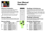
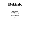
_____________________________ CRA-200 Analog Telephone Adapter 2 x Ethernet Port + 2 x VoIP Line Quick Installation Guide CRA-200 Quick Installation Guide Table of Contents VoIP ATA Package Contents............................................................... 2 Checklist ................................................................................................ 2 IMPORTANT SAFETY INSTRUCTIONS ..................................... 3 Connecting Your VoIP ATA................................................................. 3 Accessing your ATA Web Panel........................................................ 3 VoIP / SIP Configuration Setup through Web Panel ............... 4 Upgrading Your Firmware.................................................................. 5 Appendix: Number of Phone Lines and Bandwidth Considerations......................................................................................... 5 Recommended Number of Simultaneous Calls .................... 6 Model No: CRA-200 ___________________________________________________________________________________________________________________ Page: 1 of 7 _____________________________ CRA-200 Quick Installation Guide Power Adaptor Ethernet Cable (RJ 45) VoIP ATA Package Contents Quick Installation Guide (this document) Analog Telephone Adapter Unit (CRA-200) Standard Telephone cable (RJ11) Checklist Before you begin, make sure you have the following: • An active Internet connection • An active Internet Telephone Service Provider (ITSP) account and its settings • A cable/DSL modem or Wireless Router (Access Point) • One computer for configuration of the Phone Adapter • An analog telephone or fax machine with an RJ‐11 phone cable ___________________________________________________________________________________________________________________ Page: 2 of 7 _____________________________ CRA-200 Quick Installation Guide IMPORTANT SAFETY INSTRUCTIONS 9 Place this router on a stable surface. 9 Only use the power adapter that comes with the package. Using a different voltage rating power adaptor may damage this ATA. 9 Do not use this ATA in high humidity or high temperatures. 9 Do not open or repair the case yourself. Connecting Your VoIP ATA 5. Power on the cable/DSL modem. 6. Connect the included power adapter to the ATA’s power port, and then plug the power adapter into an electrical outlet. The power LED on the front panel will light up as soon as the Phone Adapter powers on. 1. Power off your network devices, including your modem and PC. 2. Connect one end of an RJ‐11 phone cable to the Phone Adapter’s PHONE 1 port. Connect the other end to your analog telephone or fax machine as shown below: 7. Power on your PC. Make sure your PC’s Ethernet adapter is set to obtain an IP address automatically. NOTE: Wait until the POWER, LAN and WAN LED's turn green and remain stable on the Front Panel of your ATA. 3. Connect one end of an Ethernet network cable to the LAN port of the ATA. Connect the other end to the Ethernet port of your PC. 4. Connect one end of a different Ethernet network cable to the WAN port of the ATA. Connect the other end to your cable/DSL modem as shown in below figure Accessing your ATA Web Panel 1. First, connect the ATA’s LAN port to your PC network card and then disable & enable the Local Area Connection available in the Control Panel ‐> Network Connections. Then ATA will release the IP address in the series of 192.168.113.X. And then launch the web browser on the PC. Enter http://192.168.113.1 in the Address field ___________________________________________________________________________________________________________________ Page: 3 of 7 _____________________________ 2. 3. 4. 5. (192.168.113.1 is the default local IP address of the ATA). Then press the Enter key. Or you can login to the ATA through the WAN IP address if both ATA and PC are connected to the same network (which is connected to the DHCP server), then you can get the IP address of the ATA through the phone connected to ATA by dialing “ * * ”. Then it will announce the current WAN IP Address, which is released by the DHCP server. Then enter WAN IP address in the web browser address field to get Login Screen. Now you will be brought to a Login screen. Be sure to select “Admin” in User Type and use following login information: • User Name: admin • Password: admin The ATA Status screen will appear. Then Click the Network Config ‐> WAN tab to proceed to the appropriate instructions for your Internet Connection Type: DHCP, Static IP, or PPPoE. • DHCP: Select “Automatic configuration via DHCP Server” to get the IP address automatically from DHCP server. • PPPoE: Select “Using ISP Account (PPPoE)” to enter the PPPoE user name in the User Name field, and enter the PPPoE password in the password field. • Static IP: Select “Using Static IP” to assign the IP address manually by entering IP Address, Subnet Mask, Gateway, Primary and Secondary DNS. Click on “Apply Changes” to save your settings. CRA-200 Quick Installation Guide VoIP / SIP Configuration Setup through Web Panel 1. Enter the information supplied by your VoIP service provider to register your SIP account such as User ID, Password, Proxy IP address etc. In the VoIP Config >>SIP Config page, do the following: a. Enter the SIP account number in the following fields: • Display Name • Authentication User ID • User ID b. Enter the password in the Password field. c. Enter the SIP proxy server name in the following fields: • IP Address/Host Name • SIP Proxy Domain NOTE: By default, the Proxy port address will be 5060, DTMF will be RFC2833, Registration Timeout will be 60 seconds. All codec configurations will be selected in Active Codecs. 2. Click on “Apply Changes” to save your settings. 3. Check if the corresponding Phone LED on the front of the device turns orange, which is illuminated to indicate successful registration with your VoIP Service Provider (ITSP). If not, please check your settings. 4. In order to make sure your Internet connection is active, you can also use the Ping or Traceroute options available in the Diagnostic Tab page to check the connection from the CRA‐200 device to another destination (IP address or domain name). ___________________________________________________________________________________________________________________ Page: 4 of 7 _____________________________ CRA-200 Quick Installation Guide 7. Once the upgrade completes, a new pop‐up window will inform you that the device will automatically reboot. Click OK. (The browser window should close on its own unless the browser window has other page tabs opened in that window, such as with IE 7 or Firefox browsers.) 8. Wait about 5 minutes for the device to complete the reboot. You can verify this by checking to see that the WAN light on the box starts to flicker (indicating network activity). 9. After verifying that the device has rebooted, hold down the red RESET button on the back of the device (in between the PHONE2 port and the power slot). Upgrading Your Firmware IMPORTANT: Before you perform the upgrade, make note of any account and server settings, plus any other unique configurations you have set up on your device. 1. From your Internet browser, enter the WAN IP address of the device to bring up the Web Configuration Login page. IMPORTANT: Make sure that the PC being used for upgrading is not directly connected to the LAN port of the device prior to upgrading. Performing the firmware upgrade procedure in this manner may result in device failure. 2. Enter the login information to enter the Web Configuration Manager. (Upon login, you should be directed to the Diagnostic page.) 3. Click on the ATA Config tab, and then click on the “Firmware Upgrade” link. 4. From the Firmware Upgrade page, select the “Browse…” button and select the firmware file from your local PC directory. 5. Once the file has been selected and the directory location is visible in the ATA Firmware Upgrade File: line entry box, select the Update button. (A pop‐up window should appear with a warning to not disrupt the power connection during the upgrade procedure.) 6. Start the upgrade procedure by clicking OK. Initially, the screen goes blank. You will then see an upgrade status indicator, which notes completion progress of the upgrade (i.e., 67% done). Hold this button down for about 7‐10 seconds until you see all the LED lights turn off except for the POWER light. (This is necessary in order to clear the cache memory upon upgrading. After the device reboots, you will need to re‐enter your device configuration.) Appendix: Number of Phone Lines and Bandwidth Considerations The virtual private network (VPN) tunnel capability on the CRA‐ 200 device affects the bandwidth consumed by each active phone call (both on the device as well as on any client connected ___________________________________________________________________________________________________________________ Page: 5 of 7 _____________________________ to the device’s LAN port). Therefore, it is important that you consider the number of total phone lines you will be attaching to each CRA‐200 device in addition to the two lines that are already available. In the sample configuration shown below, where you have one CRA‐200 box with VPN enabled and two additional Internet phone devices for a total of 4 phone lines, a 128 Kbps Internet connection will allow for no more than 4 simultaneous phone calls at a given time when using codec G.729/ Latency Configuration of 60ms (see page 10 for a brief explanation of Codec Latency Configuration). CRA-200 Quick Installation Guide Recommended Number of Simultaneous Calls The following chart depicts a general guideline range for the recommended maximum number of simultaneous calls when VPN capability is enabled for each codec/Latency configuration. The amount of allowable simultaneous phone calls and its call quality are directly related to bandwidth availability and its utilization. DSL Speed 128k 256k 384k 512k 768k 1024k 729 90ms 4-6 max. calls 10-12 17-19 23-25 36-38 48-51 729 60ms 4-5 max. calls 8-10 13-15 18-20 28-30 38-40 729 30ms 2-3 max. calls 5-6 8-9 11-13 17-19 23-26 DSL Speed 128k 256k 384k 512k 768k 1024k 723 90ms 5-7 12-14 18-20 26-28 41-43 56-58 723 60ms 4-5 9-11 15-17 20-22 32-34 43-45 723 30ms 2-3 5-6 8-9 11-13 17-19 23-26 ___________________________________________________________________________________________________________________ Page: 6 of 7 _____________________________ For example, in networks with 128k DSL, a total of no more than 7 simultaneous calls are recommended with a G.723 90ms codec configuration and VPN enabled. CRA-200 Quick Installation Guide stability of your connection. For example, if you drop one packet due to connectivity issues, a setting of G.723/30ms will lose one voice sample where a setting of G.723/90ms will lose 3 voice samples. NOTE: The DSL speeds in the table above refer to the Minimum Upload and Download transfer rate. Please be aware that your internet bandwidth may fluctuate depending on your provider’s availability. Results may vary depending on fluctuations of bandwidth availability. A decrease in available bandwidth will directly relate to a decrease in total number of allowable calls and possibly call quality depending on bandwidth overutilization. IMPORTANT: These figures assume that the bandwidth is dedicated solely for these voice calls and that the broadband service provider has committed this bandwidth to the installation. The use of other Internet services may adversely affect the amount of allowable simultaneous calls along with call quality. . Codec Latency Configuration: This setting on the SIP Configuration page determines the voice samples per packet. The number of voice samples per packet is another factor in determining the bandwidth utilized and delay of a VoIP call. The CODEC defines the size of the sample (G.711 and G.729 have a sample size of 10ms and G.723 has a sample size of 30ms), but the total number of samples placed in a packet affects how many packets are sent per second. When you increase the voice payload size, the bandwidth utilized is reduced and the overall delay increases. Increasing these settings (for example ‐ from 30ms to 90ms for G.723) can reduce bandwidth utilization, but in turn it may affect voice quality depending on the quality and ___________________________________________________________________________________________________________________ Page: 7 of 7