1
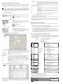
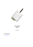
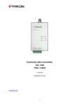
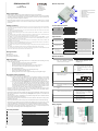
GSM module CG5
Module components
Trikdis, JSC
Draugystės st. 17,
LT-51229 Kaunas
Email: [email protected]
www.trikdis.lt
(v.2.XX)
Installation manual
1 – Terminal block for external contacts
2 – SIM card holder
3 – USB port for setting up parameters
4 – GSM antenna
5 – indicator “Network”
6 – indicator “Data”
7 – indicator “Power”
Safety requirements
Liability restrictions. Please read this manual carefully before using the security module CG5.
Security module CG5 shall be installed and maintained by qualified personnel, having specific knowledge
regarding the functioning of GSM devices and safety requirements. The device must be disconnected from
power supply source before starting device installation.
Module CG5 shall be mounted in places with restricted access and in safe distance from any sensitive
electronic equipment. The device is not resistant to mechanical effects, dampness and hazardous chemical
environment.
Liability restrictions
Terminal block description
When buying the Device, the Buyer agrees that the Device is a part of a security system of premises, which sends messages
about security system status. The Device, when installed, does not diminish the probability of burglary, fire, intrusion or other
breach of premises.
Contact
+E
COM
IN1...IN4
OUT1
COM
MCI
UAB “TRIKDIS” is not responsible for burglary, fire or any other breach of Buyer’s and/or User’s premises and is not liable for
any direct or indirect damages incurred thereof.
When buying the Device, the Buyer agrees that the Device supplied by UAB “TRIKDIS” fully meets his requirements for
intended use.
Description
+12 V power supply clamp
Common clamp
Input clamps (NC type)
Output clamps (OC type)
Common clamp
Programmable input clamp
UAB “TRIKIDIS” provides no guarantees that the Device shall function as declared if the Device is installed and used not
according to its original purpose, user manual and relevant electronic and technical conditions.
UAB “TRIKDIS” is in no way associated with GSM/GPRS/Internet service providers (operators), thus UAB “TRIKDIS” is in no way
responsible for any defects in Device operation if they have occurred because of the loss of GSM/GPRS/Internet connection, or
because of other defects in the service provider network.
UAB “TRIKDIS” has no control and is not responsible for the prices and marketing of network services provided by the
GSM/GPRS/Internet service providers.
Light indication
LED
Indicator Network
displays connection with
GSM network status
Operation
Green flashing
Green ON
Yellow flashing
UAB “TRIKDIS” is not responsible if GSM/GPRS/Internet services are not provided to the Buyer and/or User of the Device or
were cancelled and any direct or indirect damages were incurred thereof.
UAB “TRIKDIS” is not responsible for any direct or indirect damages incurred by the Buyer and/or User of the Device due to loss
of electricity.
Yellow ON
Green ON
Red ON
Red flashing
Red flashing rapidly
Green flashing
Indicator Data displays
data buffer status
UAB “TRIKDIS” is not liable if Device firmware versions were not updated by the Buyer and/or the User on time.
User manual of the Device can contain technical inaccuracies, grammatical or typographical errors. UAB “TRIKDIS” reserves the
right to correct, update and/or change information in the installation manual.
Package contents
The Module CG5
GSM antenna of straight type
Two-sided adhesive tape (10 cm)
1 pc.
1 pc.
1 pc.
Indicator Power displays
all power supply status,
functioning of
microcontroller and
programming status.
Yellow flashing
Green and yellow flashing in
turn
Module installation
Actions
GSM module CG5
1.
Set Module operating parameters by
using the CG5config configuration
software installed in a computer.
2.
Insert an activated SIM card
CG5 is a device, which sends SMS messages with text to 1-4 mobile phones about disturbing the security
system of the premises. Features:
−
−
−
−
−
−
−
−
Description
Is registering to GSM network
Connection to GSM network at present is
Number of yellow flashes represent GSM
signal strength
SMS message is being sent
Memory contains unsent messages
Messages are unable to be sent
Module configuration is incorrect
SIM card error
Power supply is sufficient, microcontroller
is functioning properly
Power supply is not sufficient (≤11,5 V),
microcontroller is properly functioning
Programming mode
Sends SMS messages if one of the input circuits is broken at least
Every SMS message contains exact event time stamp
Supports texts about events are set with Lithuanian, Latin or Russian characters
User can be alerted about the sending of SMS messages with a phone call
Power-supply voltage control
LED indication about device operation status and GSM signal strength
Output can be controlled with an SMS message
Operating parameters can be set with a program CG5config or by sending SMS messages
Notes
Follow instructions given in chapter
Setting operating parameters with a
computer, page 5.
a)
b)
Contact a GSM service provider
order to receive a SIM card. We
not recommend using pay as you
SIM cards.
SIM card PIN code request must
disabled.
in
do
go
be
3.
Fasten the module to the control panel
metal casing by using M3x6 screws or an
adhesive fastening tape
4.
Screw the GSM antenna on.
5.
Connect the Module to other security
system devices according to the schemes
given below.
6.
Switch on the security system power
supply.
7.
Evaluate if GSM signal strength is
sufficient according to Light indication.
Sufficient GSM signal strength is level 5
(five yellow flashes of indicator Network).
If GSM signal strength is not sufficient,
use other antenna type.
SMS messages can be sent to 1-4 mobile phones. It is possible to configure how User can be alerted and what
type of messages should be sent to every phone.
8.
Set the Module internal clock.
Send SMS message to the Module with
information about time
Module can 1-9 times call to every chosen phone from the list to alert Users about events in security system.
Call duration is 20 seconds.
9.
Check if the module sends SMS messages.
Take notice if time shown in the received
SMS message corresponds to the time of
the actual event.
Description of Device Operation
The location and dimensions of holes to
be drilled in the casing for fastening the
module and antenna:
Module CG5 can be set to operate in one of the two modes:
a) Constant input control mode (24 h). After the control panel has changed the state of its PGM
output, this causes module input circuit breaking. Module CG5 immediately sends an SMS
message with pre-set content to a mobile phone. When the input circuit state restores, the
module will send an SMS message about this event. General wiring diagram is given in Fig. 1.
b) Switched input control mode (Control panel). When operating in this mode, input MCI functions
as an input status controller. While input MCI is connected with COM, disturbances in inputs
IN1...IN4 are ignored and SMS messages about them are not sent. After the MCI input circuit has
been broken, the module CG5 will send an SMS message informing that the inputs are Under
Control and disturbances in inputs IN1...IN4 circuits will no longer are ignored. When circuits of
the inputs IN1...IN4 are broken, module will send messages about these events.
Output OUT1 can be used to connect a siren. Siren is activated when the module CG5 registers an event.
Switching off mode Under Control deactivates the siren as well. Switching on the mode Under Control is
followed by one short siren signal and switching off – by two.
Module CG5 has five NC / NO / EOL=2.2 kΩ type inputs. When operating in 24 h mode, module MCI input is the
fifth 24 hour managed input, and when operating in Control panel mode it operates as a controller for the
other four inputs.
SMS messages will include an event time stamp, when the module internal clock is set with an SMS message.
Possible Wiring diagrams are given in
page 5.
Output OUT1 is open collector type and can commutate direct voltage up to 30 V and current up to 1 A. If the
output is set to Siren mode, after disturbing the input circuits the output will be activated for two minutes.
Sending interval for periodic “Test” messages is from 1 to 240 hours. Text of Test message can be customized.
Wiring diagrams
Module monitors power supply voltage. When voltage drops below 11,5 V, a message informing about the
drop in voltage is sent. Message is also sent when voltage restores to 12,6 V.
Technical parameters
Power supply voltage
Used current
GSM modem frequency
Sending messages
Memory
Inputs
Output
Test message sending interval
Setting configuration
Operating environment
Dimensions
DC 12,6 ± 3 V
60–100 mA (stand-by mode)
Up to 250 mA (transmitting mode)
850 / 900 / 1800 MHz
Text SMS messages up to 4 mobile phones
Up to 60 messages
4+1, NC / NO / EOL=2.2 kΩ
1 OC type, commutating up to 30 V voltage and current up to 1 A
0 ÷ 240 h
Through the USB port or with SMS messages
From -10 °C to 50 °C, with relative air humidity 80% when +20 °C
65 x 79 x 25 mm
Fig.1 General wiring diagram to the control panel when
constant input control mode (24 h) is set.
Fig.2 General wiring diagram when switched input control
mode (Control panel) is set.
Telephone number
Setting of operating parameters with a computer
We recommend using program CG5config for setting up module CG5 operating parameters. This will allow
setting parameters of the equipment quicker and easier. The program can be found on website www.trikdis.lt.
1.
Connect the module CG5 with computer USB port. Computer must have appropriate USB drivers
installed.
Note: If the module CG5 is connected to a MS Windows OS computer for the first time a new Found New Hardware Wizard
window should open for installing new USB drivers. This window means that a USB driver has to be installed in order to
connect to the module CG5 properly. Download the USB driver file USB_COM.inf from website www.trikdis.lt. In the wizard
window select the function Yes, this time only and press the button Next. When a new window Please choose your search
and installation options will open, press the button Browse and select the place where the file USB_COM.inf was saved.
Follow the remaining wizard instructions to finish USB driver installation.
2.
Start the program CG5config.
3.
Select the program directory Settings.
In the drop-down list Port select the port to which the module is
connected.
Note: specific port to which the device is connected is shown only when
the device is properly connected.
In the drop-down list Language select the desired software
language.
4.
Press the button Connect/Disconnect [F2/F8]
When the module CG5 is connected to a computer, module LED
indicator Power should flash green and yellow in turn, and
CG5config status bar should indicate connection status
Connected. Further information about the connected module
should be displayed in status bar:
6.
By checking boxes below the GSM numbers, you can choose how each recipient will be alerted and which type
of messages will be sent to them:
SMS
SMS messages will be sent when appropriate input circuit is broken (box E) and
restored (box R),
Call
A call will be made to alert that appropriate input circuit is broken (box E) and
restored (box R),
LP
SMS messages will be sent when informing about disturbances in power supply chain,
Test
Module shall send test messages to the recipient according to the time period set in
the field Test every.
ACK
Module CG5 shall send confirmation about command execution to the recipient who
has sent the command.
8.
Press the button Save [F6] and set configuration will be uploaded to Module CG5.
9.
Press the button Disconnect [F8] and unplug USB cable.
A set configuration file can be created with extention .gst and saved in the computer by the pressing the
button Save [F5]. The file as a templet can be used in the future.
If you need to restore Module CG5 default parameters, press the button Restore [F11] and press the button
Confirm when request window newly opens. Module CG5 default operating parameters can be restored any
time before unplugging the USB cable.
Module firmware version updating
Module type
When the manufacturer adds new features to the Module CG5, firmware of the previously bought CG5 can be
updated:
Module serial number
1.
Download the latest CG5_xxx.prg update file from the website www.trikdis.lt.
2.
Connect the Module CG5 to a computer and start the CG5config program. Select the directory Firmware
in program CG5config and select the downloaded update file CG5_xxx.prg.
Enter your access code and press the button OK in the opened
window Access code (default access code is 1234).
3.
Firmware update will start after pressing the button Start [F9]. Wait until Progress bar reaches 100%,
then press the button Disconnect [F8] and unplug the USB cable.
If you want CG5config to remember your access code check the
box Remember. Then the Access code window will not open,
when connecting to the module for the next time.
4.
Plug the USB cable back in and press one by one the buttons Connect [F2] and Read [F7]. The new
version of Module firmware will be displayed in status bar of the program CG5config. Now you can set
additionally configuration according to the manner described in previous chapter. If you don’t need this,
press the button Disconnect [F7] and unplug USB cable.
Firmware version installed in the module
5.
Enter the GSM numbers of mobile phones, to which the module will send SMS
messages and/or will make calls. Module parameters can be set or the state of
output OUT1 can be controlled by sending SMS messages only from phones having
these numbers. GSM numbers should be entered with international country code
without the “+” (plus) sign.
Press the button Read [F7]
Set the following parameters in the directory SMS reporting.
Setting of operating parameters with SMS messages
Some Module operating parameters can be set by sending SMS messages from authorised phone to the GSM
number of the SIM card inserted in the Module. If function ACK for confirming SMS commands is set, Module
will send back SMS messages with confirmations that: COMMAND OK, Wrong COMMAND!!!, Wrong
PASSWORD!!!, Wrong DATA!!!.
-
SMS syntax:
<Command>space<Password>spaces<Data>
For example:
SETN 1234 PHONE1=+37068700000
Here:
SETN – command
1234 – password
PHONE1=+37068700000 – data
Note: All commands in SMS message have to be written in capital letters.
Ser No
1
Command
SETL
Content
ENG
RUS
LIT
2
SETN
PHONE1=+370xxx
PHONE2=+370xxx
PHONE3=+370xxx
PHONE4=+370xxx
Access code
Default access code 1234 must be changed to one known by you and other
authorised persons only. This code is used for setting operating parameters of the
module and/or to control the state of output OUT1 with SMS messages. When
changing the password, enter a desired four-digit sequence.
Account name
If desired, enter the name of the object. Account name will be included in SMS
messages.
SMS text encoding
Select the format of SMS text encoding in the drop-down list.
Operation mode
Select the desired module CG5 operating mode: either 24 h or Control panel. If there
is set NO or NC type, all five inputs will respectively become either NO or NC. If there
is set EOL type, inputs IN1...IN4 will become EOL=2.2kΩ and the input MCI – NC.
Output
Select the desired output OUT1 operating mode. If you connect a siren to the output,
select the option Siren. If you would like that after receiving a command with SMS
message, the module would change the state of its output, select the option Remote
control by SMS.
Test time
Enter a desired time period according to which the module will send a periodic
message with text entered in the row Test.
Call
When event occurs module will call to User pre-set number of times.
7.
PHONE1=DEL
PHONE2=DEL
PHONE3=DEL
PHONE4=DEL
3
SETE
TEST
ACK
CALL
SMS
4
TXTA
5
TXTE
<Text>
Z1=<Text>
........
Z6=<Text>
6
TXTR
Z1=<Text>
........
Z6=<Text>
Choose the directory SMS reporting and set desirable parameters used for reporting.
7
TIME
8
PSW
<Time>
New PSW
9
RESET
10
INFO
11
SLEEP
Meaning
Setting of language:
English
Russian
Lithuanian
For example: SETL 1234 ENG
Entering of recipients’ telephone numbers:
st
1 GSM number
2nd GSM number
3rd GSM number
th
4 GSM number
For example: SETN 1234 PHONE1=+37068700000
Deleting of recipients’ telephone numbers:
st
1 GSM number
2nd GSM number
rd
3 GSM number
4th GSM number
For example: SETN 1234 PHONE1=DEL
Distributing of messages by their type:
Enabling sending of Test message
Enabling sending of acknowledgements about
command executing
Enabling calling if event happens
Enabling SMS sending if event happens
For example: SETE 1234 PHONE1=... TEST=ON ACK=ON
CALL=OFF SMS=ON
Setting of object name:
For example: TXTA 1234 Object name
Customising of SMS with alarm text:
Z1...Z6 – input number
For example: TXTE 1234 Z1=ALARM in Zone1
Customising of SMS with restore text:
Z1...Z6 – input number
For example: TXTR 1234 Z1=Restore Zone1
Setting of internal clock:
For example: TIME 1234 YYYY/MM/DD,12:00:00
Setting of password:
New password (4 digit)
For example: PSW 1234 4321
Module reset:
For example: RESET 1234
Request for info about module state:
For example: INFO 1234
Stop sending of SMS that have been unsent till RESET
command:
For example: SLEEP 1234
Remote switching of PGM output OUT1
In order to change state of output OUT1 you need to send an SMS message to the SIM card GSM number of the
Module. Examples of SMS messages are provided in the table below.
Note: All commands have to be written in capital letters.
Zone alarm/restore events can be described with a text. Enter your texts in appropriate text-boxes. When input
circuit is disturbed, an SMS message will be sent with text from the appropriate text-box Event message. When
input circuit is restored – from the text-box Restore message. Texts which describe events in power supply
chain can be entered in the box LP. There can be entered desirable text which will be included in periodic
message in the box Test.
SMS syntax
Meaning
Pataba
OUTPUT 1234 ON
Output turns to position ON (circuit closes)
1234 – default password. Instead
OUTPUT 1234 OFF
Output turns to position OFF (circuit opens)
of this, enter your.
OUTPUT 1234 PULSE=005
Output turns to position ON for entered time (sec)
Note: Output state can be switched only when operating mode of the Module is set as 24h and output operating mode is set
as Remote control by SMS.