1
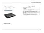
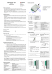
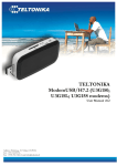
Teltonika WirelessCOM/G10
User’s Manual 4.0.1
Address: Žirmūnų g. 27, Vilnius LT-09105,
Tel.: +370 5 2127472,
Fax: +3705 276 1380, E-mail: [email protected]
2
TABLE OF CONTENTS
Teltonika WirelessCOM/G10.............................................................................................................. 1
User’s Manual 4.0.1............................................................................................................................. 1
TABLE OF CONTENTS .................................................................................................................... 2
1. ATTENTION............................................................................................................................... 3
2. SAFETY MEASURES................................................................................................................ 4
3. BASIC INFORMATION ............................................................................................................ 5
3.1 About this document.................................................................................................................. 5
3.2 Legal Notice .............................................................................................................................. 5
3.3 Contacts ..................................................................................................................................... 5
3.4 Acronyms................................................................................................................................... 5
4. PACKAGE CONTENTS ............................................................................................................ 6
5. FEATURES ................................................................................................................................. 7
6. INTRODUCTION ....................................................................................................................... 8
6.1 Wired Solution........................................................................................................................... 9
6.2 Wireless solution using WirelessCom/G10............................................................................. 10
7. CONFIGURATION .................................................................................................................. 11
7.1 Preparing WirelessCOM/G10 configuration ........................................................................... 11
7.2 PC setup................................................................................................................................... 11
7.3 Entering into configuration mode............................................................................................ 12
7.4 Command set ........................................................................................................................... 12
7.5 Configuration parameters ........................................................................................................ 15
7.6 Configuration through GPRS and CSD................................................................................... 18
7.7 Configuration through SMS .................................................................................................... 19
7.8 SMS details.............................................................................................................................. 20
7.8 SMS formats ............................................................................................................................ 21
8. TECHNICAL SPECIFICATION .............................................................................................. 23
8.1 General..................................................................................................................................... 23
8.2 LED indications....................................................................................................................... 23
8.3 Operating parameters............................................................................................................... 24
8.4 Mechanical characteristics....................................................................................................... 24
8.5 Version numbering .................................................................................................................. 25
8.4 WirelessCom/G10 customization ............................................................................................ 25
9. ENDING.................................................................................................................................... 26
APPENDIX I ..................................................................................................................................... 27
APPENDIX II.................................................................................................................................... 29
2
3
1. ATTENTION
All wireless devices for data transferring are susceptible to
interference, which could affect performance
Only qualified personnel may install or repair this product
The device is not water-resistant. Keep it dry.
Do not mount or serve device during a thunderbolt.
3
4
2. SAFETY MEASURES
This section will provide guidelines on how to use WirelessCOM/G10 device safely. We
suggest you to adhere to following recommendations so as to avoid any damage to person or property.
You have to be familiar with the safety requirements before you start using the device!
Installation and technical support of the device can be performed
only by a qualified personnel or a person who has enough
knowledge about this device and safety requirements.
The device requires 9 V power supply. Available power supply source range is 6 V up to
15 V, power up to 3500mW.
The PC and power supply source to which the device is
connected
should
satisfy
LST
EN
60950-1
standard.
WirelessCOM/G10 modem can be used on first (Personal
Computer) or second (Notebook) computer safety class.
To avoid mechanical damage of the device, it is recommended to transport the device
packed in damage-proof pack.
While using the device, place it such that the LEDs are visible to the user. It’s because
these LEDs provide information about the working modes and conditions of the device.
Signal level of the WirelessCOM/G10 depends on the environment in which it is
working.
If the device fails to work properly only qualified personnel may repair this product. We
recommend to disconnect the device and forward it to repair centre or to the manufacturer. The
modem does not contain any parts which can be replaced.
At the installation site, supply circuits must have protective devices (bipolar release
device) which provide protection from short-circuit and wrong ground installation. The power of
connected device should satisfy power of release device. The interstice between contacts should be no
less than 3mm. Power supply network should be installed near the device on an easily accessible place
4
5
3. BASIC INFORMATION
3.1 About this document
This manual describes the Teltonika WirelessCOM/G10 hardware, configuration and
operation. The manual would help the users to deploy, configure and operate WirelessCOM/G10.
3.2 Legal Notice
Copyright © 2007 TELTONIKA Ltd. All rights reserved. Reproduction, transfer,
distribution or storage of part or all of the contents in this document in any form without the prior
written permission of TELTONIKA Ltd is prohibited.
Other products and company names mentioned herein may be trademarks or trade names of
their respective owners.
3.3 Contacts
If you face any problems related to the device, which you are not able to solve by
yourself, please contact your local distributor.
3.4 Acronyms
APN
AC/DC
CSD
GPRS
GSM
PC
M2M
ISP
PIN
SIM
SMS
TCP/IP
Access Point Name.
Alternating Current/Direct Current
Circuit Switched Data.
General Packet Radio Service.
Global System for Mobile communications.
Personal Computer.
Machine-to-Machine.
Internet Service Provider.
Personal Identification Number.
Subscriber Identity Module.
Short Message Service.
Transmission Control Protocol/Internet Protocol.
5
6
4. PACKAGE CONTENTS
Teltonika WirelessCOM/G10 is packed in a box and contains all the accessories required for
normal operation:
ª
WirelessCOM/G10.
ª
AC/DC adapter.
ª
RS232 serial cable.
ª
External GSM antenna.
ª
CD with User Manual.
ª
Leaflet “Quick Start Guide”.
Note: The manufacturer does not supply the SIM card, which is mandatory for setting up a
connection to the GSM network! The SIM card may be purchased from your GSM (mobile) service
provider!
If any of the components are missing please contact your local distributor.
6
7
5. FEATURES
•
Provides transparent GPRS/CSD connection
•
Receive SMS alerts when exceptions occur in device
•
No drivers required, hence works with any device/machine/equipment/computer
•
Simple and informative configuration menu
•
Configurable through any terminal software
•
Hardware reset from DTR pin (optional)
•
Device is remotely configurable through GPRS/CSD/SMS
•
Access only through authorized phone numbers (for CSD and SMS)
•
Up to 5 configurable authorized phone numbers
•
Auto PIN feature, no need to enter SIM card PIN after restart
•
Password protected configuration
•
Dual colour LED indication for various states of device (Up to 9 states)
•
Supports various data formats (8N1,8N2,8E1,8O1,7E1,7O1)
•
Firmware update possibility
•
CHAP/PAP authentication supported
•
CE certified
7
8
6. INTRODUCTION
Many times a need is felt to upgrade software of a remotely situated device/machine, or
monitor its parameters, or receive warnings on malfunctioning to a remotely situated server. Taking
advantage of the large mobile networks and their supporting GPRS features, it is now possible to
connect devices in the field back to a central server simply and cost-effectively. Using wireless cellular
technology, serial devices such as PLC, Modbus, RFID scanners, data loggers, electricity meters,
pumps, valves, POS (Point-Of-Sales) terminals and such other equipments can be connected to a
central processing server without the requirement for cables to be installed. All you need is a device
which has a serial port, and WirelessCom/G10. Just configure and connect WirelessCom/G10 to your
device/machine and your device/machine would easily turn it into a device which can be accessed from
any remotely located server.
WirelessCOM/G10 is exactly what its name says; it is a wireless COM port. When
WirelessCOM/G10 is connected to any equipment with COM/RS-232 ports, it just replaces the
physical cable (RS232) connection by wireless GSM network. This means, the length of RS232 cable
would be as long as a GSM network. Thus, as far as a GSM network is available, this device will be
accessible from any part of the world. In simple words, WirelessCom acts as a bridge between serial
port and GPRS. All the information coming through GPRS/CSD is sent to serial port and all the
information coming on serial port is sent to GPRS/CSD. In short there is a transparent connection
between WirelessCom and the server/PC (for example) without any physical limits.
Physical contact
Virtual contact
INTERNET/
CSD call
6.1 b)
6.1 a)
Figure 6.1: RS232 connections
WirelessCom is basically an intelligent pre-programmed modem for making GPRS/CSD
connections and handle the exceptions arising during the process of making connection. Thus you
don’t need an external microcontroller to control WirelessCom using AT commands. All you need is to
configure WirelessCom (the configuration parameters are explained in later sections) and it will
automatically make connections using the configured bearer (GPRS/CSD). If anything goes wrong, for
example GPRS activation failed/CSD call could not be established/GPRS connection could not be
8
9
established/CSD call was not answered, you would receive SMS indicating the errors and the
concerned parameters.
Once configured, connect (physically) WirelessCom to the serial port of your remote
device/machine and you would be able to access your device remotely through GPRS/CSD.
Additionally, if you want to change the configuration parameters of WirelessCom you can do it
remotely using GPRS/CSD/SMS.
The next section would explain 2 scenarios 1) Typical wired connection which is being
used by most of the users. 2) A solution which would turn your wired connection into a wireless
solution so that you would have remote access, control and monitoring of your device/machine
through GPRS/CSD.
6.1 Wired Solution
A typical wired setup includes a device/machine with a RS232 port connected to the
serial port of the PC using a normal RS232 cable, refer fig 6.1. The user then launches some proprietary
software which came with the device/machine (or it can be a terminal software) and connects the
software to the same serial port to which device/machine is connected, refer fig 6.1 (b). Thus a
connection between device/machine and the software has been established. Now the user can
configure, operate, collect data, program the device/machine and perform such various operations. In
short the user is in total control of the device/machine.
RS232 cable
(Physical connection)
6.1 (a)
RS232 cable
(Physical connection)
Proprietary software
running on PC
Hardware serial
port of PC
PC/Server
6.1 (b)
Figure 6.1: Typical wired setup
9
10
6.2 Wireless solution using WirelessCom/G10
A typical setup may look as shown in figure 6.2, WirelessCom may be connected
(physically) to any device, machine (which has a RS232 port) located in a remote place and the server
computer would be present at the company/home. Through various parameters settings (server ip,
server port, apn……) present in WirelessCom, it would be configured to connect to the server.
On the server would be running two software’s,
a) TCP-to-Serial software/Telnet/TCP port software: TCP-to-serial software is only required if
you have dedicated (proprietary) software which you use to control/configure/read/write your device.
This software is used to create a virtual serial port on your computer. This port will appear as a
hardware port for your computer. The main function of this software is to direct all the data coming on
the TCP port to the virtually created serial port.
If you are using simple terminal software for interacting with your device, in that case you
can use any Telnet software* (Microsoft Telnet) or a TCP port communication software like Netcat
and set a TCP/IP port in listening mode.
*Refer to APPENDIX II for more details
b) Proprietary software: This software (can be even a free terminal software) is used to make
a connection from PC to the device/ machine using normal serial port (as explained in the scenario of
wired solution). Launch this software and connect it to the virtually created serial port. The setup is
done and your proprietary software is now connected to your device/machine remotely through GPRS.
Your device
WirelessCom/G10
INTERNET
Proprietary
software
running on PC
Virtual serial port
(TCP-to-Serial
software)
Serial connection
(Physical)
Ethernet/GPRS/Wireless
Telnet software with TCP/IP
port in listening mode
PC/Server
Figure 6.2: Wireless setup
10
11
7. CONFIGURATION
7.1 Preparing WirelessCOM/G10 configuration
Before inserting or replacing SIM card – WirelessCOM/G10 should be switched off!
Otherwise, WirelessCOM/G10 or SIM card may get damaged!
1. Insert a GPRS enabled SIM card into WirelessCOM/G10.
2. Connect the physical serial port of WirelessCOM/G10 with COM port of PC (or other device),
using a usual RS232 cable. (If you want to configure do not turn ON WirelessCOM/G10 yet)
* For initial configuration disable PIN query of your SIM card (If active)
7.2 PC setup
1. Launch Hyper Terminal (it is provided with windows) or any other terminal software on your
PC.
2. In New Connection window put the name of your connection, Etc.: WirelessCOM G10
3. In the field Connect using choose the COM port which you are using to connect
WirelessCOM/G10 and click OK.
4.
In Port Settings window (see Figure 7.2.1) choose:
ª
Bits per second: 9600.
ª
Parity: None.
ª
Stop bits: 1.
ª
Flow control: None.
Now click OK button.
Figure 7.1: Port Settings window
11
12
The setup for configuration is ready now, however if you want to see the characters which you are
typing on hyper terminal, proceed to next steps,
5.
In the File menu choose Properties and Settings. In the opened window choose ASCII
Setup.
6.
Switch on (see Figure 7.2.2):
ª
Send line ends with line feeds.
ª
Echo typed characters locally.
Click OK.
Figure 7.2: ASCII Setup window
7.3 Entering into configuration mode
1. Click the button Call on Hyper Terminal toolbar.
2. Power-up WirelessCom/G10 from the AC/DC adapter.
3. When the status LED starts to blink green (device initialization) press and hold spacebar on the
Hyper Terminal window, until a message: “Welcome to WirelessCOM/G10 Configuration
console. Firmware version: xx.xx.xx” appears. LED will blink green and yellow alternately to
indicate configuration mode.
* Once WirelessCom/G10 is powered-up, for the initial 8 seconds it is waiting to see if user
wants to enter into configuration mode or not. Once these 8 seconds are elapsed you cannot
enter configuration mode, you would need to restart the device.
7.4 Command set
Now you can use the commands for a full configuration of the device. To see all the
available commands enter help command in configuration console and you will get a list of commands
with their short description. The commands are described in brief below,
1) get: This command will give you the information about configuration parameters
of WirelessCom/G10. If you need information about all the parameters, just type get
and press enter/return key. To get the information about individual configuration
parameter, type get xxxx where xxxx is the name of configuration parameter, and
12
13
press enter/return key.. For example, get mode this command will give you the
information about the mode in which WirelessCom/G10 is configured.
2) set: This command performs 2 functions,
a) It gives you the information about all the configuration parameters and their valid
values. To get this info, just type set and press enter/return key.
b) This command is also used to enter the values of configuration parameters. Type
set xxxx yyyy and press enter/return key, where xxxx is the configuration parameter
name and yyyy is the value of configuration parameter. For example set bearer gprs
this command will choose the bearer type as gprs.
3) test: Once you have configured all the necessary parameters, you can use this
command to check if the settings are fine and if WirelessCOM/G10 is able to make
connections using GPRS/CSD bearer. If test is used for CSD bearer,
WirelessCOM/G10 will try to connect to the number configured in csd_phone.
Therefore make sure that the phone number is correct and ensure that csd_phone will
answer the call from WirelessCOM/G10. If test is used with GPRS bearer in master
mode, then WirelessCOM/G10 will try to activate gprs and connect to the configured
ip address and port. When the GPRS connection with server is established
WirelessCom/G10 will make a small data transfer (all the information about
configuration parameters) and then close the connection.
4) clear: This command is used to clear the values of string parameters. These
parameters include username, userpassword, device_id, password, apn, auth_phone1,
auth_phone2, auth_phone3, auth_phone4, csd_phone. To clear a particular value, type
clear xxxx where xxxx is the name of configuration parameter, and press enter/return
key, for example clear username You can clear all the string parameters and some
numerical parameters in one time by typing clear all If you will type only clear and
press enter/return key, it will show you the parameters which can be cleared by using
this command.
5) restart: This command is used to restart WirelessCOM/G10. Type restart and
press enter/return key.
6) pin: If you have a sim card with enabled pin, WirelessCOM/G10 gives you the
possibility to enter the pin (of sim card) automatically each time the device restarts.
13
14
Using this command, WirelessCOM/G10 will store the pin in its memory and
whenever the device restarts WirelessCOM/G10 will enter the pin automatically. To
save a pin type pin xxxx where xxxx is the pin of your sim card, and press
enter/return key.
7) puk: If you have a sim card with enabled puk, WirelessCOM/G10 gives you the
possibility to enter the puk (of sim card) automatically each time the device restarts.
Using this command, WirelessCOM/G10 will store the puk in its memory and
whenever the device restarts WirelessCOM/G10 will enter the puk automatically. To
save a puk type puk xxxx where xxxx is the puk of your sim card, and press
enter/return key.
In addition to the above commands, there are commands for preset connection
profiles of GPRS and CSD connections. Using these commands you can set the
configuration settings for a particular bearer and mode to typical values. They are as
explained below,
8) gprs_master: This command will set WirelessCOM/G10 to gprs master mode
configuration with typical values (factory configured). Just type gprs_master and press
enter/return key.
9) gprs_slave: This command will set WirelessCOM/G10 to gprs slave mode
configuration with typical values (factory configured). Just type gprs_slave and press
enter/return key.
10) csd_master: This command will set WirelessCOM/G10 to csd master mode
configuration with typical values (factory configured). Just type csd_master and press
enter/return key.
11) csd_slave: This command will set WirelessCOM/G10 to csd slave mode
configuration with typical values (factory configured). Just type csd_slave and press
enter/return key.
* Whenever you have configured WirelessCom/G10, before restarting the device use the test
command. The command will test WirelessCom/G10 with your current configuration settings and
check if connection is possible or not. However if you had made changes to mode, bearer or
bearer_retry_timeout, you would need to restart the modem and then use the test command
14
15
7.5 Configuration parameters
The table below explains all the configuration parameters, with their syntax and description.
Nr.
1.
2.
Parameter
MODE
CONNECTION
TIMEOUT
Syntax
set mode xxx
get mode
set connection_timeout
xxx
get connection_timeout
3.
BAUD RATE
set baud xxx
get baud
4.
DATA FORMAT
set data_format
get data_format
5.
6.
*PIN
*PUK
pin xxx
puk xxx
7.
BEARER
set bearer xxx
get bearer
8.
BUFFER SIZE
set buffer_size xxx
get buffer_size
9.
BUFFER TIMEOUT
set buffer_timeout xxx
get buffer_timeout
Description
Slave mode means that the device is
always online and waiting for TCP/CSD
connection. In order to reach device in
this mode you would need to insert a sim
card with static IP.
Master mode (recommended mode)
means the device initiates the TCP/CSD
connection to the configured server_ip
(only when data arrives on COM port).
Master_ar mode means the module will
always try to be connected to the server
even if no data is available on COM.
*Restart is required after you set this parameter
(in order for the change to take effect)
This setting decides the duration of
connection. If there is no data
transmitted/ received during the specified
time,
module
drops
TCP/CSD
connection.
Value (in seconds) should be from 0 to
86400. If value is “0”, connection will
newer be dropped.
The baud rate of the serial port. Baud rate
can be: 1200, 2400, 4800, 9600, 19200,
28800, 57600 and 115200.
It sets the data format for serial port. The
supported data formats and acceptable
values are, 8N1,8N2,8E1,8O1,7E1,7O1
Enter PIN code for the SIM card
Enter PUK code for the SIM card
Selects the bearer, which will be used for
data transfer. You can choose between
CSD and GPRS.
*Restart is required after you set this parameter
(in order for the change to take effect)
Size of output buffer in bytes. If
buffer_size=0 or buffer_size=1, the bytes
are sent the same moment they are
received.
Value should be from 0 to 4096. Typical
value is 1024; recommended value for
large data transfers is 4096.
If the buffer is not full when this period of
time elapses, the buffer is sent anyway.
Value (in seconds) should be from 0 to
15
16
10.
11.
12.
13.
set call_type xxx
get call_type
set username xxx
USER NAME
get username
set userpassword xxx
USER PASSWORD
get userpassword
AUTHENTICATION set auth_protocol xxxx
PROTOCOL
get auth_protocol
CALL TYPE
14.
LOCAL PORT
set local_port xxx
get local_port
15.
SERVER IP
set server_ip xxx
get server_ip
16.
SERVER PORT
set server_port xxx
17.
BEARER RETRY
TIMEOUT
set bearer_retry_timeout
xxx
get bearer_retry_timeout
18.
PING
19.
APN
20.
CSD PHONE
set ping xxxx
get ping
set apn xxx
get apn
set csd_phone xxx
get csd_phone
21.
AUTHORIZED
PHONE NUMBER
set auth_phone1 xxx
get auth_phone1
(similarly auth_phone2,
auth_phone3,
auth_phone4)
22.
DEVICE ID
set device_id xxx
get device id
86400. Typical value is 200
Call type can be analog or isdn. Typical
value is isdn.
user name for gprs connections which
require CHAP/PAP authentication
Password for gprs connections which
require CHAP/PAP authentication.
Sets the authentication protocol. Value
can be none, chap, pap.
Sets local port to listen for incoming
connections. Value should be from 0 to
65535.
Remote server IP. Valid IP format is:
xxx.xxx.xxx.xxx
Remote server port. Value should be from
0 to 65535.
It decides the time for which
WirelessCOM/G10 should try to connect
to a server (GPRS) or make a call (CSD).
Value (in seconds) should be from 0 to
300. If the value is “0”, then the device
keeps trying infinitely.
*Restart is required after you set this parameter
(in order for the change to take effect)
This is a timeout which would send an
empty packet to the server (if connection
is established) after the timeout occurs.
This timeout can also be called as keep
connection alive timeout. Many times
operators drop GPRS connections if a
traffic is not detected on a particular
connection, this timeout can help to
prevent such situation.
Access Point Name
CSD connection phone number.
Sets authorized phone number for
accepting, sending SMS. Authorized
numbers for accepting CSD calls in slave
mode. Calls and SMS coming from other
phone numbers would be rejected. Valid
phone format is: +xxxxxxxxxxx
Gives an ID for the device. If configured
this ID will be transmitted along with data
transferred over GPRS/CSD. The ID will
be included only in the first packet. Any
character/string
with
numeric
or
alphanumeric values.
This parameter is helpful if you have more
than one WirelessCom in the field. You
can enter name of city/address and it will
be easier for you to recognize from which
16
17
23.
*PASSWORD
set password xxx
get password
24.
BEARER FAIL
REPORT
set bearer_fail_report xxx
get bearer_fail_report
25.
CLOCK
set clock xx:xx
get clock
26.
**AUTOCONNECT
set autoconnect xx:xx
set autoconnect xxxx
get autoconnect
device the data came.
Password protection for configuration of
WirelessCOM/G10. If configured, after
restart, entry to configuration console
would be possible only after correct
password.
Any character/string with numeric or
alphanumeric values. No spaces allowed.
Maximum characters 10.
Value on/off. If on, you will receive SMS
(with additional information, as will be
explained in the SMS section) if: GPRS
activation failed; GPRS connection to
server failed; GPRS server could not be
created; CSD connection failed; CSD call
was not answered.
This parameter is used to set the real time
clock of WirelessCom/G10. It is a 24
hours clock. Valid values are from 00:00
to 23:59
This parameter allows you to configure
WirelessCom/G10 such that the device
will connect to the server at the
configured time. In clock-based approach,
time can be entered in terms of clock
hours (for this feature it is necessary to
configure the clock parameter) for
example, 15:30 this means everyday
WirelessCom/G10 will automatically
connect to the server at 15:30. In timebased approach, time can be entered in
minutes (clock parameter does not need to
be configured) for example, 200 this
means WirelessCom/G10 will connect to
the server after every 200 minutes.
Table 7.1: WirelessCOM/G10 general configuration settings
* pin,puk,password are not displayed in the normal configuration menu (the menu which appears
when you type get and press enter). Instead you have to access them individually by typing get xxxx,
where xxxx is the name of configuration parameter.
** Autoconnect feature is only available for GPRS bearer in master mode. The feature is disabled
when WirelessCom/G10 is in configuration mode
*** If you are making CSD call to WirlessCom/G10, make sure that you are not hiding your caller
id. If not WirlessCom/G10 will not be able to recognize the incoming caller id and would reject the
call.
17
18
7.6 Configuration through GPRS and CSD
WirelessCom/G10 can also be configured through a remote computer if there is an
established GPRS or CSD connection between WirelessCom/G10 and the PC. All the commands
(except test) and configuration parameters are supported. Configuration through GPRS/CSD will be
the same as if you were directly connected to WirelessCom/G10. However there is one change, every
command should start with * and finish with #.
Nr.
1.
2.
3.
4.
5.
6.
7.
8.
9.
10.
11.
12.
13.
14.
15.
16.
17.
18.
19.
20.
21.
22.
Parameter
Syntax
*set mode xxx#
MODE
*get mode#
*set tcp_connection_timeout xxx#
TCP CONNECTION TIMEOUT
*get tcp_connection_timeout#
*set baud xxx#
BAUD RATE
*get baud#
*set data_format xxx#
DATA FORMAT
*get data_format#
PIN
*pin xxx#
PUK
*puk xxx#
*set bearer xxx#
BEARER
*get bearer#
*set ping xxxx#
PING
*get ping#
*set buffer_size xxx#
BUFFER SIZE
*get buffer_size#
*set buffer_timeout xxx#
BUFFER TIMEOUT
*get buffer_timeout#
*set call_type xxx#
CALL TYPE
*get call_type#
*set username xxx#
USER NAME
*get username#
*set userpassword xxx#
USER PASSWORD
*get userpassword#
*set auth_protocol xxx#
AUTHENTICATION PROTOCOL
*get auth_protocol#
*set local_port xxx#
LOCAL PORT
*get local_port#
*set server_ip xxx#
SERVER IP
*get server_ip#
*set server_port xxx#
SERVER PORT
*getserver_port#
*set bearer_connection_timeout xxx#
BEARER CONNECTION TIMEOUT
*get bearer_connection_timeout#
*set apn xxx#
APN
*get apn#
*set phone xxx#
BEARER PHONE
*get phone#
*set auth_phone xxx#
AUTHORIZED PHONE NUMBER
*get auth_phone#
*set device_id xxx#
DEVICE ID
*get device id#
18
19
23.
PASSWORD
24.
BEARER FAIL REPORT
25.
CLOCK
26.
AUTOCONNECT
*set password xxx#
*get password#
*set bearer_fail_report xxx#
*get bearer_fail_report#
*set clock xx:xx#
*get clock#
*set autoconnect xx:xx#
*set autoconnect xxxx#
*get autoconnect#
Table 7.2 WirelessCOM/G10 configuration through CSD and GPRS
* Changes in mode, bearer will take place only after you will restart the WirelessCom/G10. It is
possible to restart WirelessCom/G10 remotely by using the command *restart#. We recommend you
to check all the settings and restart WirelessCom/G10 after you are done with remote
configuration.
7.7 Configuration through SMS
After WirelessCom/G10 registers to the network, it scans for SMS every 5 seconds. SMS can
be used to configure/get parameters of WirelessCom/G10. Access through SMS is allowed only to an
authorized phone number. Currently five authorized numbers are allowed.
Nr.
Parameter
Syntax
1.
GET1
get1
2.
GET2
get2
3.
4.
RESTART
SERVER IP
ADDRESS
5.
SERVER PORT
6.
APN
7.
MODE
8.
AUTH PHONE
restart
ip xxx.xxx.xxx.xxx set
e.g: ip 192.168.2.1 set
port xxxx set
e.g: port 1234 set
apn xxxxxxxxxx set
e.g: apn web.gsm set
mode xxxxx set
mode slave set
auth_phone1 +********** set
e.g: auth_phone1 +1234567890 set
(Similarly you can set auth_phone2,
auth_phone3, auth_phone4)
Description
Gets the information about the
essential
GPRS
configuration
parameters of WirelessCOM/G10.
(Format of received SMS is
explained in later section)
Gets the information about the
essential
CSD
configuration
parameters of WirelessCOM/G10.
(Format of received SMS is
explained in later section)
Restarts WirelessCOM/G10
Sets the IP address of server
Sets the server port
Sets APN
Sets the mode of device. Master,
slave or master_ar
Sets the authorized SMS phone
number.
Table 7.3: WirelessCOM/G10 configuration through SMS
19
20
An SMS can include single parameter or multiple parameters. When multiple parameters are to be
configured separate them with spaces. You don’t need to include “set” after every parameter. Just type
the parameters you want to configure along with their corresponding values and end the message with
“set”. e.g: ip 222.222.222.222 port 1234 apn web.gsm mode slave auth_phone1 +123456789 set
* It is very important that you type the SMS in lowercase, if not SMS configuration will fail. Also
each sms should end with set (except get1,get2 and restart), if not, only the parameters before set
would be configured, anything after set will be discarded.
** If you make a mistake (in format of sms or values of parameters) while sending sms, you will
receive a sms which would include errors.
***restart command will only be executed if there were no errors during configuration through
sms. We recommend you to restart WirlessCom/G10 after you have finished the configuration
(mode and bearer would only be changed after restart).
7.8 SMS details
WirlessCom/G10 has been programmed to send SMS (if configured) to the user in case of following
conditions,
•
GPRS activation fails
•
GPRS Server setup fails
•
CSD call fails
•
CSD call was not answered
(To receive SMS for above conditions bearer_fail_report should be on. SMS will be sent to
auth_phone1 first, if not configured/or sms fails, next numbers will be tried)
•
SMS request by user for getting configuration information
•
Error during configuration through SMS
•
Invalid command format sent through SMS
20
21
In order to save valuable space in SMS, some of the parameters have short values,
Parameter
Value (as visible in SMS)
GPRS
0
GPRS is not active
1
GPRS is active
0
Slave mode
1
Master mode
2
Master_ar mode
0
Bearer is GPRS
1
Bearer is CSD
0
Analog
1
ISDN
MODE
BEARER
CALL TYPE
Description
Table 7.4: Parameters and their values in SMS
Some of the configuration parameters names which are longer are being expressed in short form, as
shown in the table 7.4,
Configuration parameter
Configuration parameter
(as visible in SMS)
device_id
DEV_ID
server_port
SER_PRT
bearer_retry_timeout
RETRY_TO
connection_timeout
CONN_TO
csd_phone
CSD_PH
auth_phone1,auth_phone2,auth_phone3,auth_phone4
AUTH_PH [,,,,]
Table 7.4: Parameters and their short form in SMS
7.8 SMS formats
Authorized users can send SMS to WirelessCom/G10 to get information about configuration
parameters. There are 2 commands to which would WirelessCom/G10 would reply,
•
SMS sent to WirelessCom/G10 : get1
•
Reply from WirelessCom/G10 : DEV_ID[ ]GPRS[ ]MODE[ ]IP[ ]SERPRT[ ]APN[
]BEARER[ ][USR: ,PSWD: ]
•
SMS sent to WirelessCom/G10 : get2
•
Reply from WirelessCom/G10: DEV_ID[ ]AUTH_PH[ , , , ]CSD_PH[ ]CALL_TYP[
]BAUD[ ]RETRY_TO[ ]CONN_TO[ ]
21
22
If bearer_fail_report is turned on, WirelessCom/G10 is programmed to send SMS for
conditions which would result in no connection (GPRS/CSD). The conditions and the format of
received SMS are as explained below,
1) Initialization of GPRS was not successful. This condition may occur if either of
apn, username or userpassword is not configured properly.
GPRS initialization failed MODE[ ]IP[ ]SER_PRT[ ]LOCALPRT[ ]APN[
][USR: ,PSWD: ]
2) WirelessCom/G10 was not able to connect to server (GPRS). This condition will
arise in master mode if server_ip or server_port parameters are not configured
properly.
Connection to server failed DEV_ID[ ]IP[ ]SER_PRT[ ]APN[ ][USR:
,PSWD: ]RETRY_TO[ ]CONN_TO[ ]
3) WirelessCom was not able to create a server (GPRS). This condition will arise in
slave mode if local_port was not configured properly.
Server creation failed DEV_ID[ ] GPRS[ ] LOCALPORT[ ] APN[ ] [USR:
,PSWD: ]
4) WirelessCom could not activate GPRS. This condition may occur if any of the
following configuration parameters were not configured properly, apn, username,
userpassword, It may also happen if GPRS service is not activated on the SIM card.
GPRS activation failed DEV_ID[ ]MODE[ ]IP[ ]SER_PRT[ ]RETRY_TO[
]APN[ ][USR: ,PSWD: ]
5) CSD connection could not be established. This may happen if authorized phone
numbers were not properly configured.
CSD call failed DEV_ID[ ]MODE[ ]AUTH_PH[ , , , ]CSD_PH[
]RETRY_TO[ ]CONN_TO[ ]
6) CSD call generated from WirelessCom/G10 was not answered.
CSD call not answered DEV_ID[ ]MODE[ ]AUTH_PH[ , , , ]CSD_PH[
]RETRY_TO[ ]CONN_TO[ ]
22
23
8. TECHNICAL SPECIFICATION
8.1 General
GSM:
Quad band: 850/900/1800/1900 MHz
GPRS Class 10: 16-24 Kbps upload, 32-48 Kbps download
CSD: Up to 9.6 Kbps
SMS: Text mode
RS232 interface:
Socket: DB9 female
Data rate: Up to 115200
Data bits: 7,8
Parity: Odd, Even
Flow control: No
8.2 LED indications
Two LED indicators (“Power” and “Status”) are located on the top of WirelessCOM/G10.
These LEDs indicate the operating mode and failure conditions of the device. WirelessCOM/G10
operating modes are described in table 8.1
LED
Power
Status
Status
Status
Status
Status
Status
Status
Status
Status
Status
COLOUR
Green
Green
Green
Green
Green
Orange
Orange
Orange
Orange
Orange
Green & Orange
STATUS
ON
ON
Blinking slowly
Double blinking
Blinking continuously
ON
Blinking slowly
Double blinking
Triple blinking
Blinking continuously
Blinking alternately
DESCRIPTION
Power is ON
GPRS/CSD master mode
Initialization
GPRS activation/connection failed
GPRS/CSD connected (master mode)
GPRS/CSD slave mode
Connecting….
No SIM card
PIN/PUK not entered
GPRS/CSD connected (slave mode)
Configuration mode
Table 8.1: WirelessCOM/G10 operating modes
23
24
8.3 Operating parameters
The Teltonika WirelessCOM/G10 internally uses linear power regulator. The PC (or any other
device) where WirelessCOM/G10 is to be connected must have a RS232 interface. Electrical and other
parameters are shown in table 8.2.
Parameter
Power supply voltage
Power consumption
Minimal
+6.0
45
Nominal
+9.0
Maximal
+15.0
4000
Units
V
mW
Table 8.2 WirelessCOM/G10 operating parameters
Note: modem may malfunction if the environment conditions do not conform to
those provided in the Table!
Note: The device must be powered with AC/DC adapter provided by manufacturer!
8.4 Mechanical characteristics
WirelessCOM/G10 housing is made of plastic. It is light and suitable for use in varied
environments. WirelessCOM/G10 has following connectors:
1. DB9 Female connector for connecting to a PC (or other device).
2. SIM card holder.
3. 3.5 mm /1.35 mm power supply connector.
4. SMA connector for external GSM antenna.
6,3 cm
2,2 cm
4.
9,4 cm
1. 2.
3.
24
25
8.5 Version numbering
WirelessCom/G10 has the possibility of software updates. This will ensure that any issues
arising can be fixed, and new functionality can be added by just updating the firmware.
WirelessCom/G10 uses standard version numbering system for the firmware and the manual,
xx.xx.xx
1) The first 2 digits explain the main version of firmware/manual. Change in these digits
indicates that some major functionality/changes have taken place.
2) The middle 2 digits explain the minor changes/functionality that has been added to
firmware/manual of WirelessCom/G10.
3) The last 2 digits explain the release number for a particular version. If the first 4 digits
remain the same and only the last 2 digits are increasing, it means there were some issues
with the previous releases which have been fixed in this release. Increase in the last 2 digits
does not mean that new functionality has been added, it only means that issues of previous
releases have been fixed.
8.4 WirelessCom/G10 customization
WirelessCom/G10 is a versatile device and it would fulfill your requirements in most of the
situations. However, sometimes you may have a special requirement; you may need WirelessCom/G10
to communicate with your device in some special way, or some changes in communication protocol, or
some additional functionality. If you would have such requirements please let us know, we can provide
customized firmware *FREE OF CHARGE.
*Depends upon the level of customization and the quantity of orders. Please feel free to ask.
25
26
9. ENDING
This sign on the package means that it is necessary to read the User’s Manual, which
is on the CD, before starting using the device.
This sign on the package means that used electronic and electric equipment should be
stored separately.
26
27
APPENDIX I
CSD connection:
CSD stands for Circuit Switched Data, it is a data transmission protocol over GSM
networks. To establish a CSD connection between two modem-equipped devices (like
WirelessCom/G10), one of the modems should initiate a call (dial-up). The procedure is the same as
making a voice call. Just dial the phone number of the modem with which you want to establish a
connection. (Connection is possible only if both the modems are GSM modems, a connection
between an analog modem and GSM modem may not be successful) and the other modem should
answer the call (it can be automatic or call will have to be answered manually). The steps for
establishing a CSD call with a WirelessCom/G10 is explained in the following section. Before
starting with the following steps make sure you have read the complete users manual.
1) Enter into the configuration console of WirelessCom/G10 (as explained in the section 7.17.3 of user manual).
2) Configure the device for CSD connection, or you can use the default profiles csd_slave or
csd_master. Configure the authorized phone number (necessary if you are planning to make
a CSD connection in master mode) and CSD phone (necessary if you are planning to make a
CSD connection in slave mode).
3) Once you have configured all the necessary parameters, test the device by entering the test
command. The testing command will help you to analyze the working of modem with your
configured parameters.
A) Slave mode:
If you are testing the device in slave mode, it will perform various steps (after you have
entered the test command) and if everything is OK then it will wait for an incoming call. If
you want to make a data transfer then you should have another GSM modem and dial-up the
*phone number of WirelessCom/G10. (Remember to configure the phone number of dialing
modem in the authorized phone number of WirelessCom/G10). If you have configured the
settings properly then you would see RING on the terminal program screen and after end of
third ring WirelessCom/G10 will answer the call. Once the connection is established you
can make a data transfer.
B) Master mode:
If you are testing the device in master mode, it will perform various steps (after you have
entered the test command) and if everything is OK it will make a CSD call to the *phone
number which is configured in csd_phone. If the receiver modem answers, the connection
27
28
will be established and you can make a data transfer. If the receiver modem will not
answer/cancel the call, WirelessCom/G10 will display “CSD connection failed”.
4) If the calls during the test were successful it means your configuration settings were correct
and the device is ready to **work with the configured settings.
5) Restart the device, upon restart the device will start its initializing procedure and the status
LED will help you follow the various states of the device.
6) If everything is fine the status LED will be either orange (slave mode) or green (master
mode). In slave mode the device is waiting for an incoming call. In case of master mode,
whenever some data arrives on the serial port WirelessCom/G10 will start making connection to
the configured csd_phone number.
* Usually the phone number for voice calls and CSD calls are the same, however there may be
some operators who provide separate phone numbers for voice and CSD connection.
** In order to confirm the working of WirelessCom/G10 with CSD connection it is necessary
that you make a data transfer between WirelessCom/G10 and modem.
28
29
APPENDIX II
WirelessCom/G10 Master mode connection
This appendix will explain the setup for making a Wireless connection between
WirelessCom/G10 and a PC using the master mode. Master mode connection means the PC is
acting as a server and WirelessCom is acting as a client. PC will be in listening mode and will be
waiting for a connection. WirelessCom will initiate connection to the server pc whenever some data
arrives on serial port of WirelessCom. Based on the software running on the PC side two examples
have been explained.
a) Using Microsoft Telnet on Server PC
Microsoft Telnet is an application which comes pre-installed on Windows operating
systems. This application can be used to connect to other applications over the internet (provided
that you have the IP and port number of the remote application). This application can also be used
to listen for incoming connections on the Telnet port 23. Since this application is a dedicated Telnet
application, you don’t have the possibility to change the incoming port, it is always fixed to 23.
Requirements: Windows PC with Static IP (not required if you are in a VPN) and Telnet, Port
forwarding in case your PC is connected in LAN/ behind a router, Internet connection.
PC-side setup:
1) To launch Telnet application you will have to go to the command prompt.
2) On the bottom left corner of your desktop click Start and then click Run.
3) A dialog box will pop-up, in the field Open: type cmd and press OK.
4) This action will open a command window on your desktop.
5) On the command prompt type telnet and the telnet application will launch.
6) If the application does not launch then go to your root directory by using cd\ command and try
again.
7) By default it is waiting for incoming connection on port 23.
8) The next step is to configure WirelessCom to connect to your PC.
WirelessCom/G10 setup:
1) WirelessCom should be configured in Master mode.
2) Use the command gprs_master to configure WirelessCom with typical parameters.
3) Configure the parameter server_ip by entering the IP of your PC. Configure server_port as 23.
4) After you have completed the configuration, use the test command to check the working of
WirelessCom.
5) If the test is successful, restart WirelessCom/G10 and wait until it initializes and the status LED
is Green and always ON.
29
30
6) Now whenever some data arrives on the serial port of WirelessCom/G10, it will connect to the
telnet application on you PC (provided that the telnet application is running on your PC) and
transfer the data.
* Make sure that IP of your PC is public and static (not required if you are in a VPN). Following
are private IPs ,
10.0.0.0 to 10.255.255.255 ,
172.16.0.0 to 172.31.255.255 and
192.168.0.0 to 192.168.255.255
** If your PC is in LAN, behind a router, make sure that you have enabled port forwarding to the
address of your private IP (LAN IP).
b) Using Netcat on Server PC
Netcat is a software which can be used for wide variety of operations related to TCP/IP
communication. It is available for free to download. This application can be used to create a TCP
port of any number (not just 23 as in case of Microsoft’s Telnet application) and set in listening
mode.
Requirements: PC with Static IP (not required if you are in a VPN), Port forwarding in case your
PC is connected in LAN/ behind a router, Internet connection, Netcat
PC-side setup:
1) Download the application from the net
2) The application does not have any installer. The download contains the source code and an
executable file.
3) When you download the application from the net, unzip the folder and place the folder in your
root directory for example C: drive.
4) To launch Netcat application you will have to go to the command prompt.
5) On the bottom left corner of your desktop click Start and then click Run.
6) A dialog box will pop-up, in the field Open: type cmd and press OK.
7) This action will open a command window on your desktop.
8) Go to your root directory by entering the command cd\ and you would see the command prompt,
C:\>
9) To execute netcat, type the following and press the return/enter key
C:\> cd nc
10) You will now enter into the application and the prompt will look as follows,
C:\nc>
30
31
11) On this prompt use the command nc –l –v –p (there is space between –l –v –p) followed by the
allocated port number on your PC and press return/enter key.
C:\nc>nc –l –v –p 7000
12) If the port is available and you executed the command correctly, you would see a message
“listening on [any] xxxx …..”
WirelessCom/G10 setup:
1) WirelessCom should be configured in Master mode.
2) Use the command gprs_master to configure WirelessCom with typical parameters.
3) Configure the parameter server_ip by entering the IP of your PC.
4) Configure server_port as the port number which you have set for listening in Netcat, in this
particular example it is 7000.
5) After you have completed the configuration, use the test command to check the working of
WirelessCom.
6) If the test is successful, restart WirelessCom/G10 and wait until it initializes and the status LED
is Green and always ON.
7) Now whenever some data arrives on the serial port of WirelessCom/G10, it will connect to
Netcat on your PC (provided that the Netcat application is running on your PC) and transfer the
data.
* Make sure that IP of your PC is public and static (not required if you are in a VPN). Following
are private IPs ,
10.0.0.0 to 10.255.255.255 ,
172.16.0.0 to 172.31.255.255 and
192.168.0.0 to 192.168.255.255
** If your PC is in LAN, behind a router, make sure that you have enabled port forwarding to the
address of your private IP (LAN IP).
31