1
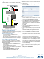
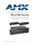
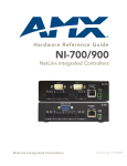
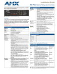
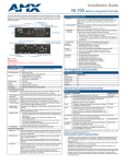
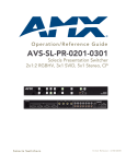
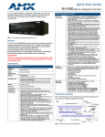
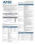
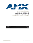
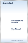
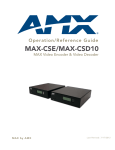
Installation Guide
MAX-CSD10 Video Decoder
MAX-CSD10 Video Decoder
MAX-CSD10 Specifications (Cont.)
This unit (FG2178-72) is engineered to provide real-time decoding of streamed digital
video content out as Composite and S-Video signals for distribution onto external
display devices such as a television, plasma screen, or projector, and video displaycapable devices such as AMX Modero Touch Panels.
Rear Panel Connectors
(Cont.):
• RS-232/422/485: Single 9-pin (DB9) port supports RS-232/422/
485 data output including:
- 300, 600, 1,200, 2,400, 4,800, 9,600, 19,200, 38,400, and
115,200 Baud rates
- 7 or 8 Data bits
- 1 or 2 Stop bits
- Even, Odd, Mark, Space, and None parity settings
- CTS and RTS handshaking
- XON/XOFF handshaking
• I/O: Two digital binary Input/Output ports for contact closure
(accepts a 4-pin 3.5mm mini-Phoenix (male) captive-wire
connector). Each input is capable of voltage sensing. Input
format is software selectable with interactive power sensing for
IR ports.
Operating/Storage
Environment:
•
•
•
•
Operating Temperature: 0° to 45° C (32° to 113° F)
Storage Temperature: -30º to 70º C (-22º to 158° F)
Operating Relative Humidity: 5% to 85% (non-condensing)
Operation intended for indoor use only.
Included Accessories:
•
•
•
•
•
2-pin 3.5 mm mini-Phoenix female PWR connector
4-pin 3.5 mm mini-Phoenix female I/O connector
BNC to RCA Adapter
CC-NIRC IR Emitter cable
MAX-CSD10 Quick Start Guide
Other AMX Equipment:
•
•
•
•
•
AC-RK Accessory Rack Kit (FG515)
CSB Cable Support Bracket (FG517)
PMB Pole Mount Bracket (FG531)
STS, Serial To Screw Terminal (FG959)
Surface Mount Bracket Accessory (FG525)
The rear Ethernet port supports IEEE 802.3af Power-over-Ethernet (POE) which
enables DC power to be supplied to this device over the unused pairs of wires on the
connected Ethernet cable. FIG. 1 shows the front and rear panel views.
ID button
Status LED
LCD Display
IR Receiver
(front)
Composite
OUT
(BNC)
S-Video OUT
Analog stereo audio
Ethernet
Input/Output
port
12 VDC
Power
(rear)
Ethernet Speed and
Link Activity LEDs
RS232/422/485
port
IR/Serial port
FIG. 1 MAX-CSD10 Video Decoder (front and rear views)
Note: This unit can be mounted onto either a flat surface or into an equipment rack by
first removing the front screws and then attaching it to an AC-RK.
Wiring Installation Procedures
The wiring parameters for the PWR, Serial, and Ethernet ports are described in detail
within the following sections.
Wiring The Power Connector
MAX-CSD10 (FG2178-72) Specifications
Use an external power supply (see Power Requirements) to provide power to the
MAX-CSD10 through the rear 2-pin 3.5 mm mini-Phoenix connector (FIG. 1). The
incoming PWR and GND cable from the power supply must be connected to the
corresponding locations within the PWR connector.
Dimensions (HWD):
1.58" x 5.54" x 6.95" (4.01 cm x 14.07 cm x 17.65 cm)
Power-Over-Ethernet (POE) Connection
Power Requirements:
•
•
•
•
•
Weight:
• 2.02 lbs (0.92 kg)
Caution: If using Power-over-Ethernet as your source of power, you must FIRST
ground the unit to provide ESD protection. Install only a single wire into the (-) GND
side of the rear green 2-pin PWR connector, and then connect the terminal-end of this
same wire to a grounded source. It is recommended that the length of this wire
NOT exceed 6 ft. (1.83 m).
Any 802.3af-compliant POE switch (such as the NXA-ENET24 POE) can
automatically detect the 802.3af-compliant MAX device by its authenticated POE
signature and sense its required load before turning on DC power to the POE Ethernet
port.
500mA @ 12VDC (6W)
Power Over Ethernet (POE) is available.
Optional 12VDC power input overrides POE when used.
Power requirements are usage dependant.
This product is intended to be supplied by a Listed external
power supply rated from 10 to 18 VDC, minimum 500 mA or
equivalent.
Enclosure:
• Metal with black matte finish
Certifications:
• FCC Part 15 Class B, CE, and UL listed
Video Outputs:
• Composite Video (via BNC)
• S-Video (via standard female S-Video connector)
Note: Power-over-Ethernet connections work with all existing Category 3, 4, 5, 5e or 6
network cabling, including patch cables and patch-panels, outlets, and other
connecting hardware, without requiring modification.
Audio Outputs:
• Analog Stereo (RCA connectors - Red/White)
Reading the Ethernet LEDs
Supported Resolutions:
• NTSC (480i)
• PAL (576i)
The MAX-CSD10 uses a standard CAT5 Ethernet cable to provide 10/100 network
connectivity between the encoder and the network (FIG. 2).
Supported Video
Codecs:
• MPEG2 (2 Mbps - 6 Mbps)
• MPEG4 (500Kbps - 3 Mbps)
Supported Audio
Codecs:
• MPEG Audio Level 2 (MP2)
• MPEG Audio Level 3 (MP3)
• AAC
Front Panel
Components:
• ID Pushbutton: Used to both set the NetLinx ID (Device only)
assignment and reset the unit back to its factory defaults.
• Status LED: Green LED blinks to indicate both the system and
communication status with the target Master.
• LCD Display: Provides system information such as the
currently used IP Address.
• IR Receiver: Receives 38KHz AMX IR codes.
Rear Panel
Connectors:
• COMPOSITE OUT: Composite Video Output (NTSC or PAL)
via a female BNC connector.
• 12VDC PWR: Single 2-pin 3.5mm mini-Phoenix (male) captivewire connector from an optional 12 VDC power supply
(overrides POE).
• S-VIDEO OUT: Mini-Din4 port for composite S-Video output.
• ETHERNET 10/100: Single RJ-45 port provides 10/100 Mbps
network communication and POE. LEDs show communication
activity, connections, speeds, and mode information (FIG. 2).
• AUDIO R/L: Two RCA connectors (Red and White) support
line-level stereo output for analog stereo signals.
• IR/Serial: Single 2-pin 3.5mm mini-Phoenix (male) captive-wire
connector is used for IR/Serial control output by generating IR
with the use of an IR emitter (while in IR mode). This port can
support high-frequency carriers of up to 1.142 MHz and can
also generate IR with no carrier frequency.
SPD - Speed LED lights (yellow) when
the connection speed is 100 Mbps
and turns Off when the speed
is 10 Mbps.
SPD
L/A
L/A - Link/Activity LED lights
(green) when the Ethernet
cables are connected and terminated
correctly. Blinks when receiving
Ethernet data packets.
FIG. 2 Layout of Ethernet LEDs
ETHERNET 10/100
Wiring the MAX-CSD10 To Receive Streamed Media Content
Assigning a Static IP Address To The Unit Via The Browser-based UI
The rear connectors are used to take an incoming media stream and then output it
as a video signal (with audio). FIG. 3 shows a sample wiring configuration where a
MAX-CSD10 receives a video stream from a remote MAX-CSE and then distributing
the content to its connected media device.
Although the initial communication to the unit is done via a DHCP connection and
since this is your stream source, it is recommended that you assign a Static IP
Address to the unit via the browser-based UI (known as the Decoder Manager) for
better system management.
1.
Access the IP Settings page by clicking the IP Settings button from within the
Decoder Manager (FIG. 4).
S-Video or COMP Video In
(DVD, VCR, etc.)
Audio In
(Stereo RCA)
(BNC)
via Ethernet
(S-Video)
Outbound Audio/Video/Data
or
Power
supply
Direct PWR
Connection
MAX-CSE
Video Encoder
•
Composite Video Out
(to target device)
(S-Video)
via Ethernet (RJ-45)
(BNC)
Inbound
Audio/Video/Data
•
and/or
MAX-CSD10
Video Decoder
FIG. 4 Example of the unit’s IP Settings page (DHCP)
White - Left Channel
Red - Right Channel
Audio In
(Stereo RCA)
MAX-CSD10
Video Decoder
2.
3.
Power
supply
Direct PWR
Connection
The BNC connector can be adapted
to use an RCA plug by using the
INCLUDED BNC to RCA Adapter.
4.
5.
6.
7.
FIG. 3 Sample wiring configuration using a CSD10 and a target device
Configuring the Communication Parameters
The MAX-CSD10 is configured to be used as a standalone unit running on a network
capable of supporting the up to a 6Mbps data rate. It is recommended that you setup
the unit locally prior to installing it within an AC-RK rack unit.
Obtaining the Unit’s Initial DHCP Address
1.
2.
•
3.
Connect an Ethernet cable to the unit’s rear Ethernet connector.
Connect the 2-pin 3.5 mm mini-Phoenix PWR connector to the rear power
connector and then apply power.
Note: The MAX-CSD10 uses the active Ethernet connection to communicate
with the DHCP Server an obtain a valid DHCP Address.
After the unit has successfully obtained an IP Address from the DHCP Server,
it then displays this obtained DHCP Address across the front LCD (FIG. 1).
Write down the new DHCP Address displayed on the front panel LCD.
8.
9.
10.
Troubleshooting
•
•
•
Communicating With The Unit Via The Browser-based UI
To communicate with the MAX-CSD10, it is necessary for the unit to first obtain a
DHCP Address. Once that address is known, you can then use your web browser to
access the browser-based User Interface (UI) pages and then configure the project,
video, and IP connection parameters.
1.
Launch your web browser.
2.
Enter the IP Address of the target unit (ex: http://192.199.99.99) into the web
browser’s Address field.
3.
Press the Enter key on your keyboard to initiate communication and launch the
initial on-screen Enter Network Password security dialog.
• The MAX unit is shipped in a secured configuration which requires the user to
enter a username and password into the on-screen security dialog before
gaining access to the UI pages.
4.
Enter the words administrator and password into their corresponding
User Name/Password fields (case-sensitive). This profile can later be changed.
5.
Click OK to enter the information and proceed to the first UI page.
This page is used to assign the method of communication used by the target
MAX-CSD10 unit.
Note that both the default IP Configuration setting is DHCP and the
corresponding read-only fields display the MAX unit’s communication
parameters obtained from the DHCP Server during the initial setup.
Click on the Static radio box to begin entering the previously obtained Static IP
Address information (typically provided by your Network Administrator).
Enter the corresponding Static IP Address, Subnet Mask, Gateway, Domain
Suffix, and Primary and Secondary DNS parameters into their corresponding
fields on this page.
Click the Apply button to refresh the screen and save your new communication parameters.
Once the browser’s progress bar indicates it has completed the temporary
acceptance of the new parameters, click the Reboot button to restart the unit
and incorporate these changes.
Once the unit powers-up, the new Static IP Address is then displayed on the
LCD after the appearance of the AMX logo. This process can take several minutes.
Confirm the new communication parameters by launching your browser and
entering the MAX’s new Static IP Address into the browser’s Address field.
Press the Enter key on your keyboard to begin the communication process
and launch the initial on-screen security dialog.
Re-enter the words administrator and password into the corresponding
User Name/Password fields.
Click OK to enter the information and proceed to the Administration page
which provides both a descriptive overview of the program stream and lists the
currently used firmware.
•
If the LCD does not display any information during the initial startup sequence,
confirm that the front-panel Status LED is blinking and receiving power.
If the L/A LED (FIG. 2) is not On or blinking, check your cables and connectors.
If the web browser cannot establish a connection to the unit’s browser-based
UI, confirm that you’ve entered the correct/new IP Address into the browser’s
Address field. If this does not correct the problem, cycle power to the unit,
confirm the displayed IP Address information, and re-enter it into your browser.
To reset the MAX unit to a factory default state, locate the ID button on the front
panel, and press and hold the button to reboot the MAX unit. All modified information, such as the Static IP Address settings and modified Username/Password, will be wiped from the unit.
Notice: MAX Products are not designed or intended to, and may not be used to,
violate anyone’s copyright or other intellectual property rights. Each user of the MAX
Products may only use the products in connection with materials legally owned or
licensed by such user and only to the extent such ownership or license rights permit
such use.
This product includes the GoAhead Web Server.
Copyright (c) 2006 GoAhead Software, Inc. All Rights Reserved.
For full warranty information, refer to the AMX Instruction Manual(s) associated with your Product(s).
065-004-2881 1/07
©2007 AMX. All rights reserved. AMX and the AMX logo are registered trademarks of AMX.
AMX reserves the right to alter specifications without notice at any time.
3000 RESEARCH DRIVE, RICHARDSON, TX 75082 • 800.222.0193 • fax 469.624.7153 • technical support 800.932.6993 • www.amx.com
93-2178-72
REV: B