1
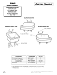
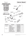
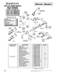
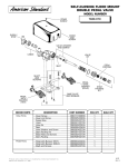
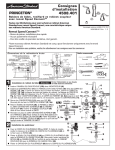
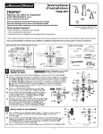
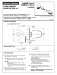
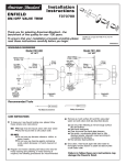
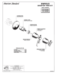
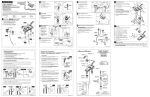
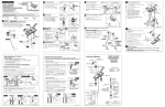
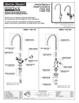
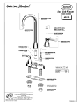
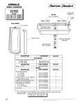
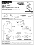
Williamsburg
Installation
Instructions
TM
7391.229
7391.224
BIDET FITTING
Thank you for selecting American-Standard...the benchmark
of fine quality for over 100 years.
To ensure that your installation proceeds smoothly--please
read these instructions carefully before you begin.
Certified to comply with ASME A112.18.1M
U.S. Patent No. 5,819,789
M968032A
Roughing-in Dimensions
8 TO 12
TRANSFER VALVE (FOR FLUSHING
RIM OR SPRAY)
BIDET OUTLINE
7/8 DIA.
IS SYMBOLIC
(C)
DIVERTER AND
VACUUM BREAKER
ASSEMBLY
2-1/4
DIA.
(H)
1-3/16 DIA.
CARE INSTRUCTIONS:
DOUCHE SPRAY
DO: SIMPLY RINSE THE PRODUCT CLEAN
WITH CLEAR WATER. DRY WITH A SOFT
COTTON FLANNEL CLOTH.
ADJ. 1-1/4
TO 2-1/4
4-1/4
1-1/4 MAX.
FOR GROUND JOINT
CONNECTION OR 1/2 "
O.D. SLIP (INLETS)
1-3/8
DIA.
3-7/8
DO NOT: CLEAN THE PRODUCT WITH SOAPS,
ACID, POLISH, ABRASIVES, HARSH CLEANERS,
OR A CLOTH WITH A COARSE SURFACE.
2-1/8
DIA.
5-1/2
FINISHED
WALL
REAR VIEW WITH
WALL REMOVED
FINISHED
FLOOR
1-1/4 O.D. TAILPIECE
1
BIDET FAUCET INSTALLATION
CAUTION
Turn off hot and cold water
supplies before beginning.
2
DRAIN INSTALLATION
STOPPER
Assemble O-RING (1), WASHER (2), PIVOT ROD (3)
and NUT (4) to DRAIN BODY (5). Concave side
of cup WASHER (2) is toward ball.
Place MOUNTING NUTS (1) onto the VALVE BODIES
(2) and insert VALVE BODIES (2) through outside
holes, from underside of the BIDET LEDGE. Drop the
RUBBER RING (3) over the VALVE BODIES (2) and
screw on the ESCUTCHEON (4) until it locks against
the internal stop.
Tighten the MOUNTING NUT (1) to secure the
VALVE BODY (2).
9
Thread LOCKNUT (6), WASHER (7) and
GASKET (8) onto DRAIN BODY (5).
PUTTY
BIDET
8
Apply a bead of PUTTY to underside
of FLANGE (9).
4
7
Remove MOUNTING NUT (9) and UPPER GASKET (7)
from TRANSFER VALVE (8) and insert into the center
forward hole of BIDET.
Feed DRAIN BODY (5) up through BIDET
and thread FLANGE (9) fully onto
BODY (5).
Tighten LOCKNUT (6) firmly, keeping the
PIVOT ROD (3) pointed towards the back
of the BIDET.
Replace UPPER GASKET (7). Position the side threaded
outlet rearward and secure MOUNTING NUT (9).
Thread ESCUTCHEON (5) onto TRANSFER VALVE (8)
until it seats against the BIDET LEDGE.
2
3
6
1
5
Push DRAIN ESCUTCHEON (10) onto
TAILPIECE (11).
5
CLIP
11
9
10
4
3
3
BIDET
LEDGE
2
COLD
HOT
1
7
8
SPRAY INSTALLATION
2
7
PUTTY
6
Assemble SPRAY BODY (1) to BIDET.
Using putty, seal underside of SPRAY
BODY FLANGE (2) and secure with
5
NUT (3).
Screw SPRAY HOSE (4) with SEAL
WASHER (5) to SPRAY BODY (1).
Connect other end of HOSE (4) with
SEAL WASHER (5) to side outlet
NIPPLE (6) of the TRANSFER VALVE (7).
Screw SPRAY CAP (8) onto SPRAY BODY (1).
8
1
7
3
5
4
4
5
LIFT ROD GUIDE INSTALLATION
3
Insert SEAL (1) into ADAPTER (2)
and tighten ADAPTER (2) to bottom
of TRANSFER VALVE (3).
Unscrew LIFT ROD NUT (1)from LIFT ROD GUIDE (2).
Make sure SEAL (3) is seated into ESCUTCHEON of
LIFT ROD GUIDE (2).
Drop LIFT ROD GUIDE (2) into
rear hole of bidet and from
below secure with ROD GUIDE
NUT (1).
TEE AND HOSE CONNECTION
Install SEAL (4) into coupling nut
of TEE (5) and tighten connection
to ADAPTER (2)
Connect HOSE COUPLING
NUTS (6) to Hot and Cold
valve bodies and securely
tighten.
2
3
1
2
6
4
6
5
1
6
7
HANDLE INSTALLATION
WATER SUPPLY CONNECTIONS
NOTE: FLEXIBLE SUPPLIES ARE NOT INCLUDED AND HAVE TO BE
PURCHASED SEPARATELY.
Push ADAPTER (1) on VALVE STEM (2), so that the hole of the
ADAPTER (1) without spline is facing up. See figure "A".
Connect water supplies to FAUCET (1) with 1/2" IPS
FLEXIBLE SUPPLIES (2) or 3/8" O.D. BULL-NOSE RISERS (3).
Use adjustable wrench to tighten connections.
Screw HANDLE BASE (3) on top of ESCUTCHEON (4) until it is snug
against stop.
Do not over tighten. Be careful not to kink copper supply
when bending. Use tubing cutter to cut to proper length.
Push LEVER BALL (5) through HANDLE BASE (3) onto ADAPTER (1).
Find correct position of LEVER BALL (5) by adjusting male teeth on
ADAPTER (1) to female teeth in LEVER BALL (5).
Secure LEVER BALL (5) with HANDLE SCREW (6).
Push INDEX CAP (7) in hole of LEVER BALL (5).
1
7
6
2
COUPLING NUT
3
5
FERRULE
3
TOP
Figure "A"
9
1
To change direction of handle rotation, proceed as follows:
2
SPLINE END DOWN
8
4
FINISH DRAIN INSTALLATION
Position BIDET fixture and
secure to floor.
Insert lift rod into lift rod guide.
Position EXTENSION ROD (1)
onto POP-UP ROD (2) and tighten
THUMBSCREW (3).
2
1
3
1
Remove one end of CLIP (4) from
PIVOT ROD (7) by squeezing ends
together while sliding.
Insert PIVOT ROD (7) into second
or third hole in EXTENSION ROD (1)
and reassemble CLIP (4).
(EXTENSION ROD (1) may need to be bent.)
SERVICE
7
Turn valve to OFF position.
Remove INSERT and HANDLE SCREW.
Slip HANDLE with ADAPTER off.
Remove SPRING CLIP (1).
Lift STOP WASHER (2), turn 90° and replace.
Replace SPRING CLIP (1).
Replace ADAPTER, HANDLE, SCREW, and INSERT.
Spray may accumulate dirt
90°
causing distorted and reduced
2
water flow. Remove spray and
rinse clean.
Replace Spray and operate
handles several times from
OFF to ON position. Do not
force, handles turn only 90˚.
1
5
4
6
Adjust STOPPER height by repositioning EXTENSION ROD (1) and
tightening THUMBSCREW (3).
Using metal TAILPIECE (5), make connection to the TRAP (6).
10
TEST INSTALLED FAUCET
With handles in OFF position, turn on water supplies and
check all connections for leaks.
Operate both handles to flush water lines thoroughly. Turn
diverter to rim wash and bidet spray.
M968032A
Williamsburg
TM
BIDET FITTING
MODEL NUMBERS
7391.229
7391.224
A918428-0070A
HANDLE SCREW
051313-YYYOA
HANDLE
051376-YYY0A
POP-UP ROD
A923348-0070A
HANDLE ADAPTER
M961702-YYY0A
TRANSFER VALVE KIT
M907617-0070A
ESCUTCHEON
TRANSFER VALVE
060353-YYY0A
PORCELAIN
LEVER HANDLE
021470-YYY0A
INDEX CAP
918428-0070A
HANDLE SCREW
M961662-0070A
TRANSFER VALVE
MOUNTING KIT
909410-YYY0A
LEVER BALL
M961656-YYY0A
LIFT ROD GUIDE
051381-YYY0A
HANDLE BASE
M921323-0070A
ELBOW ADAPTER
060354-YYY0A
METAL
LEVER HANDLE
M953130-0070A
TRANSFER VALVE
918049-0070A
HANDLE
ADAPTER
051379-YYY0A
VALVE
ESCUTCHEON KIT
066116-YYY0A
DRAIN STOPPER
072574-0070A
EXTENSION
070847-0070A
CLIP
M961663-0070A
ADAPTER KIT
066117-YYY0A
DRAIN FLANGE KIT
028610-0070A
VALVE
CARTRIDGE
066118-0070A
PIVOT ASSEMBLY
030258-0070A
VALVE
MOUNTING KIT
900984-0070A
DRAIN BODY
M961655-0070A
TAILPIECE INSERT
028704-0070A
TEE AND HOSE KIT
(INCLUDING SEALS)
028645-YYY0A
BIDET SPRAY
030280-0040A
TAILPIECE WITH
ESCUTCHEON
024220-0070A
COUPLING
NUT
Replace the "YYY" with
appropriate finish code
HOT LINE FOR HELP
For toll-free information and answers to your questions, call:
1 (800) 223-0068
Weekdays 8:00 a.m. to 7:00 p.m. Eastern Time
IN CANADA 1-800-387-0369
(TORONTO 1-905-306-1093)
CHROME, CROMO, CHROME
POLISHED BRASS
SATIN/CHROME
SATIN
SATIN/BRASS
CHROME/BRASS
002
099
221
295
297
299
028646-0070A
SPRAY HOSE
CONNECTION KIT
M968032A