1
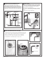
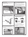
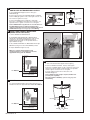
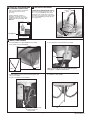
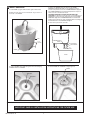
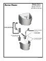
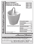
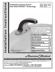
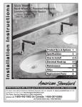
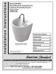
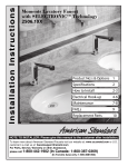
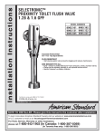
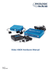
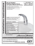
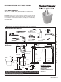
INSTALLATION INSTRUCTIONS
ICU Sink System
Models: 9118.111, 9118.100 & 9118.150
Introduction: Thank you for selecting our products...products which have been the
benchmarks of fine quality for years. To help insure that the installation process will
proceed smoothly, please read these instructions carefully before you begin. Also,
review the recommended tools and materials list; carefully unpack and examine your
new plumbing fixture.
! CAUTION: PRODUCT IS FRAGILE. TO AVOID DAMAGE AND POSSIBLE INJURY HANDLE WITH CARE!
NOTE: Pictures may not exactly define contour of china and components.
Recommended Tools & Materials
Tape
Measure
Adjustable Wrench
Plumbers' Putty or Caulking
Pipe Wrench
U S E
Torch
Hacksaw
Tubing Cutter
Channel Lock Pliers
Rough-In
Dimensions
Drill
4-3/4"
(121mm)
Phillips Screwdriver
Regular Screwdriver
20"
(509mm)
4-3/4"
(120mm)
8" (203mm)
FINISHED WALL
MOUNTING
STUDS
17"
(432mm) 5/8"
(14mm)
1-5/8"
(41mm)
F U T U R E
Pencil
Level
36-1/2"
(927mm)
2-1/2" DIA. (65mm)
14-3/4"
(375mm)
1/2" DIA.
(13mm)
40-1/8"
(1020mm)
26-1/8"
(663mm)
FINISHED
FLOOR
FINISHED
FLOOR
36-1/2"
(927mm)
9/16" DIA.
(14mm)
36"
(914mm)
2-3/4"
(70mm)
2-3/4"
(70mm)
FINISHED
FLOOR
BASE MOUNT
DETAIL
4"
(102mm)
4"
(102mm)
*DISCLAIMER: Faucets with a base diameter greater than 2-1/4" (57 mm) will not fit on this
ICU Sink. The Selectronic ICU Faucet was specifically designed to minimize splashing during
operation. American Standard will not be liable for any splashing that occurs if faucets other
than the American Standard ICU Faucets are used.
S A V E
8"(203mm) BETWEEN
MOUNTING HOLES
*FAUCET PERCH
F O R
*FAUCET PERCH
2-1/2" DIA. (65mm)
RECOMMENDED CARRIERS:
JAY R. SMITH MFG. CO.
MODEL SQ-0-4437
FLOOR MOUNTED SINK SUPPORT
WATTS CA-311
FLOOR MOUNTED URINAL CARRIER
Pro d u c t n a m e s l i s te d h e re i n a re t r a d e m a r k s o f AS A m e r i c a , I n c .
© A S A m e r i c a , I n c . 2 012
1
7301793-100 Rev. D
1
2
ROUGH-IN SUPPLIES AND WASTE OUTLET
1. Rough-in 3/8" supplies and waste outlet connections.
NOTE: For ease of installation and accessibility, it is
recommended that straight stops with flex supply tubes be
used. As an alternative, if rigid supply risers are used, it is
suggested to use angle stops in place of the straight stops.
INSTALL FAUCET
NOTE: For more detailed information, see the installation
instructions supplied with the ICU FAUCET. #(M965119)
1. Insert WIRES (1), FLEX HOSE (2) and SPOUT SHANK (3)
through center hole of mounting surface.
2. Assemble "C" WASHER (4), STAR WASHER (5) and LOCKNUT
(6) onto threads of SPOUT SHANK (3) from underside of mounting
surface.
3. Align FAUCET and tighten LOCKNUT (6).
SQ-0-4437 FLOOR
MOUNTED SINK
SUPPORT
FINISHED WALL
MOUNTING
STUDS
4
5
1-5/8"
(41mm)
36-1/2"
(927mm)
6
8" (203mm)
4"
(102mm)
4
3
2
3/8" (10mm)
SUPPLIES
5
1
6
18"
(457mm)
*1-1/4" (32mm)
OR 1-1/2" (38mm)
WASTE OUTLET
FINISHED
FLOOR
3
*CHECK LOCAL CODES
3
INSTALL GRID DRAIN AND OFFSET TAILPIECE
1. Apply plumber’s putty to the underside of flange. Install GRID DRAIN into drain outlet.
2. From the underside of SINK install RUBBER GASKET (flat side up) and FRICTION
GASKET onto GRID DRAIN threads. Apply sealent to threads of GRID DRAIN.
GRID DRAIN
3. Apply sealent to threads of OFFSET TAILPIECE and thread into DRAIN ELL.
4. Thread DRAIN ELL onto GRID DRAIN, tighten and align as shown.
DRAIN ELL
1
2
GRID DRAIN
4
FRICTION
GASKET
PLUMBER’S
PUTTY
3
DRAIN ELL
APPLY
SEALANT
RUBBER
GASKET
APPLY SEALANT
TO THREADS
7301793-100 Rev. D
2
OFFSET TAILPIECE
4
5
INSTALL ICU SINK
1. Mount SINK onto the two HANGER STUDS. Hold SINK in place
and temporarily install NYLOCK NUT & WASHER on one of the
HANGER STUDS to retain SINK.
INSTALL ELECTRONICS HANGER BRACKET
1. Install the ELECTRONICS HANGER BRACKET onto remaining
HANGER STUD. Install NYLOCK NUT & WASHER but do not
tighten fully.
2. Remove NYLOCK NUT & WASHER from first HANGER STUD
and install other end of ELECTRONICS HANGER BRACKET.
Replace NYLOCK NUT & WASHER, tighten both ends. Do not over
tighten, chinaware could become damaged.
HANGER STUD
ELECTRONICS
HANGER BRACKET
NYLOCK NUT
AND WASHER
6
7
COMPLETE WASTE OUTLET CONNECTION
1. Install “P” TRAP. Connect OFFSET TAILPIECE to “P” TRAP.
TAILPIECE may have to be cut to fit installation. Use tubing cutter to
cut TAILPIECE.
MOUNT ELECTRONICS BOX
NOTE: Installation with ELECTRONIC BOX only is for cold
or tempered water. Use optional MIXING VALVE with
ELECTRONIC BOX when Hot and Cold supplies are
roughed-in. See illustration below.
TAILPIECE
1-1/4" OD
ELECTRONIC BOX
1-1/4" or 1-1/2" OD
WASTE OUTLET
COLD WATER OR
TEMPERED WATER
(3/8" SUPPLY)
ELECTRONIC
BOX
MIXING VALVE
HOT
COLD
P-TRAP
1. Remove COVER from ELECTRONICS BOX.
2. Place ELECTRONICS BOX onto MOUNTING PLATE. Align
BOX with mounting holes. Attach with SCREWS provided.
8
3. Hang MOUNTING PLATE with ELECTRICAL BOX on
HANGER BRACKET.
CONNECT SPOUT HOSE TO ENCLOSURE
1. Connect SUPPLY NUT (1) from SPOUT assembly to nipple on
top of ENCLOSURE (2). Tighten with adjustable wrench to make a
water tight connection.
ELECTRONIC
BOX
SCREWS
1
MOUNTING PLATE
2
MIXING VALVE
3
7301793-100 Rev. D
9
CONNECT WATER SUPPLY TO ENCLOSURE
AND TO COLD OR TEMPERED WALL SUPPLY
1. Insert FIBER WASHER (4) into SUPPLY NUT (1) on
ENCLOSURE (2).
2. Connect SUPPLY NUT (1) on ENCLOSURE (2) to FLEXIBLE
SUPPLY HOSE (3). Tighten to make a water tight connection. Use
two wrenches to tighten if necessary.
1
2
4
3. Connect FLEXIBLE SUPPLY (3) directly to wall supply.
Connection on FLEXIBLE SUPPLY (3) is 3/8" compression. Use
adjustable wrench to tighten connection. Do not over tighten.
ELECTRONIC
BOX
3
COLD WATER
OR TEMPERED
WALL SUPPLY
3
Note: FLEXIBLE SUPPLY (3) measures 20" from the bottom of
the ENCLOSURE (1) base. If additional supply length is
required, installer must purchase parts separately. Important: If
FLEXIBLE SUPPLY (3) is too long, loop to avoid kinking.
10
INSTALL AND CONNECT MIXING VALVE
(MIXING VALVE IS OPTIONAL)
ADJUSTABLE
WRENCH
1. Remove COVER from MIXING VALVE.
2. Install FIBER SEAL WASHER (4) on MIXING VALVE
NIPPLE (3). Hold MIXING VALVE (1) in place with one hand
and with your other hand thread SWIVEL NUT (2) onto
MIXING VALVE NIPPLE (3). Use an adjustable wrench to
tighten SWIVEL NUT (2).
4
2
2
3. Place MIXING VALVE BOX onto MOUNTING PLATE. Align
BOX with mounting holes. Attach with SCREWS provided.
4. Replace COVER and tighten securely.
3
No. M968808
I n s t a l l a t i o n I n s t ru c t i o n s
NOTE: For complete detailed installation and
operating instructions see installations instructions
supplied with mixing valve. No. M968808
1
SELECTRONIC™
Thermostatic Mixing Valve
605XTMV
12
Certified to comply with ASME A112.18.1M
© 2005 American Standard
Specifications
1
Installation
2
Adjust Temperature
3
Service
3
Replacement Parts
4
2. Connect FLEXIBLE SUPPLIES directly to wall supplies.
Connections on MIXER supplies are 3/8" compression. Connect left
supply to Hot and right supply to Cold wall supply. Use adjustable
wrench to tighten connections. Do not over tighten.
M968808
3. Faucet supplies measure 20" from the bottom of the
ENCLOSURE (3) base.
NOTE TO INSTALLER: Please give this manual to the customer after installation.
To learn more about American Standard Faucets visit our website at: www.us.amstd.com or U.S.
customer's e-mail us at: [email protected]
For Parts, Service, Warranty or other Assistance,
please call 1-800-442-1902 (In Canada: 1-800-387-0369)
(In Toronto Area only: 1-905-3061093)
11
CONNECT MIXING VALVE TO WATER SUPPLIES
1. Turn off Hot and Cold water supplies before beginning.
Note: If additional supply length is required, installer must
purchase parts separately.
Important: If SUPPLY HOSES (1, 2) are too long, loop as to
avoid kinking.
ELECTRICAL HOOK-UP AND INSTALLATION
No. M965119
I n s t a l l a t i o n I n s t ru c t i o n s
For complete detailed installation and operating instructions see
installations instructions supplied with ICU FAUCET. No. M965119
SELECTRONIC™
Proximity ICU Faucet
6055 / 6056 ICU Faucet shown Installed on
American Standard 9118.111 ICU Sink
Certified to comply with ASME A112.18.1M
MODEL NUMBERS
6055.193
6056.193
Product No.'s & Options
1
Specifications
2
How to Install
2-3
Electrical Hook-up
4-6
Maintenance
7-8
FAQ,s
9
Replacement Parts
10
ELECTRONIC
BOX
© 2011 American Standard
M 9 6 5 119
HOT
NOTE TO INSTALLER: Please give this manual to the customer after installation.
To learn more about American Standard Faucets visit our website at: www.americanstandard.com
or U.S. customer's e-mail us at: [email protected]
For Parts, Service, Warranty or other Assistance,
please call 1-800-442-1902 (In Canada: 1-800-387-0369)
(In
(InToronto
Toronto Area
Area only:
only: 1-905-306-1093)
1-905-3061093)
7301793-100 Rev. D
MIXING VALVE
1
4
COLD
2
13
CHECK ALL ELECTRICAL AND
PLUMBING CONNECTIONS
1.Turn on water supplies and check for
leaks. Tighten any connections if
necessary.
No. M965119
I n s t a l l a t i o n I n s t ru c t i o n s
2. Check FAUCET operation, if
adjustment is required refer to the
installation instructions shown at right
supplied with the ICU FAUCET. No.
M965119.
SELECTRONIC™
Proximity ICU Faucet
14
TEST INSTALLED FAUCET
TO ENSURE A LAMINAR WATER FLOW the
air must be slowly purged from the spout. To
do so, cover the SENSOR (1) while slowly
opening the water supply valves. When the
water flows as a solid, smooth, steady stream,
uncover the SENSOR (1) and fully open the
water supply valve.
TION
DETEC
N
O
Z E
MODEL NUMBERS
6055.193
6056.193
1
6055 / 6056 ICU Faucet shown Installed on
American Standard 9118.111 ICU Sink
Certified to comply with ASME A112.18.1M
Product No.'s & Options
1
Specifications
2
How to Install
2-3
Electrical Hook-up
4-6
Maintenance
7-8
FAQ,s
9
Replacement Parts
10
© 2011 American Standard
M 9 6 5 119
NOTE TO INSTALLER: Please give this manual to the customer after installation.
To learn more about American Standard Faucets visit our website at: www.us.amstd.com or U.S.
customer's e-mail us at: [email protected]
For Parts, Service, Warranty or other Assistance,
please call 1-800-442-1902 (In Canada: 1-800-387-0369)
(In Toronto Area only: 1-905-3061093)
15
INSTALL WIRE HANGER
3. Place WIRE end in right SIDE HOLE near DRAIN.
1. Install EYEBOLT onto WIRE HANGER if not installed.
2. Place WIRE end in left SIDE HOLE.
WIRE
WIRE HANGER
WIRE
NOTE: If not enough tension, remove WIRE and spread
ends approx. 1" additional and re-attach.
EYEBOLT
4. WIRE HANGER is positioned behind ELECTRONIC BOX
and in front of DRAIN.
6. EYEBOLT for SINK APRON.
5. Remove THUMB NUT from EYEBOLT.
EYEBOLT
WIRE HANGER
REMOVE THUMB NUT
FROM EYE BOLT
5
7301793-100 Rev. D
16
INSTALL SINK APRON
3. Remove the APRON. Clean the wall where the APRON
BRACKETS supplied with SINK are to be applied. Peel off the
protective strip from the back of the APRON BRACKETS. Apply the
two APRON BRACKETS to the finished wall parallel to the pencil
marks as shown in the illustration below.
1. Hold APRON up against SINK and flush against finished wall.
2. Mark a line with a pencil on the wall about 6" long as shown on
both sides of the APRON..
OPTIONAL MOUNTING. (SCREWS AND ANCHORS NOT
SUPPLIED) Use Brackets to mark pilot holes on wall. Drill holes for
ANCHORS. Peel off the protective strip from the back of the APRON
BRACKETS. Apply the two APRON BRACKETS to the finished wall
parallel to the pencil marks as shown and aligned with the mounting holes.
See illustration below. Install SCREWS and tighten.
4. Clean off the pencil marks from wall.
SINK
PROTECTIVE
STRIP
6"
(152mm)
CLEAN WALL
PENCIL MARK
1/2"
(13mm)
APRON
APRON
5. Position APRON under SINK and against finished wall alinging
EYEBOLT with hole in APRON.
6. Retain APRON with THUMB NUT. Finger tight only.
APRON
APRON
THUMB NUT
EYEBOLT
IMPORTANT: SAVE ALL INSTALLATION INSTRUCTIONS FOR FUTURE USE
7301793-100 Rev. D
6
Repair Parts
ICU Sink System
Models: 9118.111,
9118.100 & 9118.150
7381267-400.0070A
Mounting Bracket Kit
7381243-251.0020A
Offset Drain
7381242-0500A
P-Trap Assembly
7381266-200.0070A
Bracket Assembly
7381259-401.0200A
ICU Sink Shroud Kit
7
7301793-100 Rev. D
AS AMERICA, INC. ONE YEAR LIMITED WARRANTY
If inspection of this AS America, Inc. (“American Standard”) plumbing product, within one year after its initial
purchase, confirms that it is defective in materials or workmanship, American Standard will repair or, at its
option, exchange the product for a similar model.
This limited warranty applies only to the original purchaser and installation of these products. In the event of a
limited warranty claim, proof of purchase will be required—save sales receipt.
This limited warranty does not apply to local building code compliance. Since local building codes vary
considerably, the purchaser of this product should check with a local building or plumbing contractor to insure
local code compliance
before installation.
This limited warranty is void if the product has been moved from its initial place of installation; if it has been
subjected to faulty maintenance, abuse, misuse, accident or other damages; if it was not installed in accordance
with American Standard's instructions; or if it has been modified in a manner inconsistent with the product as
shipped by American Standard.
American Standard's option to repair or exchange the product under this limited warranty does not cover any
labor or other costs of removal or installation. IN NO EVENT WILL AMERICAN STANDARD BE LIABLE FOR
THE COST OF REPAIR OR REPLACEMENT OF ANY INSTALLATION MATERIALS, INCLUDING BUT NOT
LIMITED TO, TILES, MARBLE, ETC. American Standard will not be responsible for any other incidental or
consequential damages attributable to a product defect or to the repair or exchange of a defective product, all of
which are expressly excluded from this limited warranty. This limited warranty does not cover any liability for
consequential or incidental damages, all of which are hereby expressly disclaimed, or the extension beyond the
duration of this limited warranty of any implied limited warranties, including those of merchantability or fitness for
an intended purpose. (Some states or provinces do not allow the exclusion or limitation of implied limited
warranties, so this exclusion may not apply to you.)
This limited warranty gives you specific legal rights. You may have other statutory rights that vary from state to
state or from province to province, in which case this limited warranty does not affect such statutory rights.
In the United States:
American Standard Brands
P.O. Box 6820
Piscataway, New Jersey 08855
Attention: Director of Customer Care
For residents of the United States, warranty
information may also be obtained by calling
the following toll free number: (800) 442-1902
www.americanstandard.com
In Canada:
AS Canada, ULC
5900 Avebury Rd.
Mississauga, Ontario
Canada L5R 3M3
Toll Free: (800) 387-0369
www.americanstandard.ca
In Mexico:
American Standard B&K Mexico
S. de R.L. de C.V.
Via Morelos #330
Col. Santa Clara
Ecatepec 55540 Edo. Mexico
Toll Free: 01-800-839-1200
www.americanstandard.com.mx
THIS WARRANTY IS NOT TRANSFERABLE FROM ORIGINAL CONSUMER PURCHASER.
7301793-100 Rev. D
8