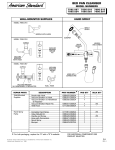
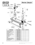
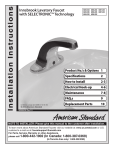
1
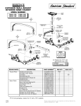
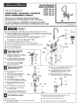
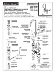
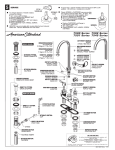
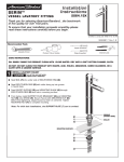
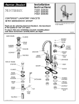
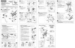
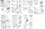
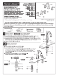
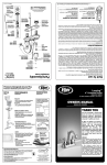
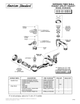
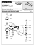
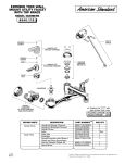
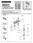
Installation
Instructions
5500
5501
5502
4" CENTERSET
LAVATORY FAUCETS
Thank you for selecting American-Standard...
the benchmark of fine quality for over 100 years.
To ensure that your installation proceeds smoothly-please read these instructions carefully before you begin.
Certified to comply with ANSI A112.18.1M
US PATENT D375785
6 0 1 8 4 R e v. 1 . 4
051322-0020A
VANDAL PROOF SCREW
GRID DRAIN
051217-0020A
WRIST BLADE HANDLE KIT
051210-0020A
LEVER HANDLE
015025-YYY0A
DRAIN COMPLETE
000690-0020A
HANDLE SCREW
051211-0070A
INDEX KIT (PAIR)
070532-0040A
TAILPIECE
066497-0020A
COMPLETE DRAIN BODY
M918014-0070A
ADAPTER
M922286-0020A
VP AERATOR,
0.35gpm/1.3L/min.
066116-YYY0A
DRAIN STOPPER
POP-UP DRAIN
066117-YYY0A
FLANGE KIT
000690-0020A
HANDLE SCREW
051211-0070A
INDEX KIT
M918014-0070A
ADAPTER
904939-0020A
BONNET NUT
028617-0020A
POP-UP ROD
951764-0070A
CARTRIDGE
M922881-0020A
AERATOR,
1.5gpm/5.7L/min.
066508-0020A
VP AERATOR,
0.5gpm/1.9L/min.
072574-0070A
EXTENSION ROD
070847-0070A
CLIP
066118-0070A
PIVOT ROD
030255-0070A
MOUNTING KIT
024220-0070A
COUPLING NUT
0-RING
900864-0070A
DRAIN BODY
TAILPIECE INSERT
070532-0070A
TAILPIECE
HOT LINE FOR HELP
For toll-free information and answers to your questions, call:
1-800-442-1902
Weekdays 8:00 a.m. to 6:00 p.m. EST
IN CANADA 1-800-387-0369 (TORONTO 1-905-306-1093)
Weekdays 8:00 a.m. to 7:00 p.m. EST
IN MEXICO 01-800-839-1200
Product names listed herein are trademarks of American Standard Inc.
Printed in Mexico.
© AS America, Inc. 2008
1
CAUTION
Turn off water at
main supply.
4
Apply a bead of PUTTY along the edge of the underside of the body.
Insert FAUCET SHANKS (5) through holes in sink.
Assemble RUBBER (1) and BRASS WASHERS (2), and LOCKNUTS (3) from
underside of SINK. Drop UPPER LIFT ROD (4) through hole in BODY
(models 5501 only), align BODY as far forward as possible
and secure position by tightening LOCKNUTS (3).
5
BODY
PUTTY
Connect the HOT water supply to the left SHANK and the COLD water
supply to the right SHANK using sealant, appropriate connectors, and
COUPLING NUTS.
SINK
2
2
3
PUTTY
SINK
Apply a bead of PUTTY around underside
of DRAIN PLUG FLANGE (1). Insert DRAIN
PLUG (2) into SINK drain hole.
2
3
4
5
Hold DRAIN PLUG (2) to prevent turning
and assemble GASKET (3), WASHER (4)
and LOCKNUT (5) from underneath sink.
Insert threaded end of TAILPIECE (6)
into lower end of DRAIN PLUG (2).
Connect other end to trap.
3
1
1
GRID DRAIN ASSEMBLY
(Model 5502 only)
2
INSTALL POP-UP DRAIN
(Model 7501 only)
HOT
Remove one end of CLIP (12) from PIVOT ROD (7)
by squeezing ends together while sliding.
8
Push TAILPIECE (1) down into TRAP
(threaded end up).
Insert PIVOT ROD (7) into second or third hole
in EXTENSION (9) and reassemble CLIP (12).
(EXTENSION may need to be bent.)
6
Thread LOCKNUT (2), WASHER (3) and
GASKET (4) onto DRAIN BODY (5).
Adjust STOPPER (8) height by repositioning
EXTENSION and tightening THUMBSCREW (12).
SINK
Apply a bead of PUTTY to underside
of FLANGE (6).
PUTTY
10
Feed DRAIN BODY (5) up through SINK
and thread FLANGE (6) fully onto BODY (5).
Tighten LOCKNUT (2) firmly, keeping the
PIVOT ROD (7) pointed towards the back
of the SINK.
Drop STOPPER (8) into DRAIN BODY (5).
COLD
11
4
3
5
12
2
7
9
12
7
Pull TAILPIECE (1) up and thread tightly
into DRAIN BODY (5).
1
Position EXTENSION ROD (9) onto POP-UP
ROD (10) and tighten THUMBSCREW (11).
TRAP
4
5
TEST INSTALLED FAUCET
Operate both handles to flush water lines thoroughly. Check
spout mounting and hose connections for leaks.
Remove AERATOR.
Operate LIFT ROD and check DRAIN for leaks.
With handle in OFF position, turn on water supplies and check
all connections for leaks.
Turn handles into OFF position and replace AERATOR.
SERVICE
90°
STOP
WASHER
To change direction of handle rotation,
proceed as follows:
Turn valve to OFF position.
Remove HANDLE and BONNET NUT.
Remove SPRING CLIP.
Lift STOP WASHER, turn 90° and replace.
Replace SPRING CLIP.
Replace BONNET NUT, HANDLE, SCREW,
and INDEX.
AERATOR may accumulate dirt causing distorted and reduced
water flow. Remove AERATOR and rinse clean.
SPRING
CLIP
If spout drips, operate handles several times from OFF to ON
position. Do not force - handles turn only 90°.
Plastic SCREEN in CARTRIDGE may accumulate
dirt causing reduced water flow. To clean, first
turn off hot and cold water supplies, then:
Remove HANDLE and BONNET NUT.
Remove CARTRIDGE by pulling up.
CARTRIDGE
Thoroughly rinse plastic SCREEN at
base of CARTRIDGE.
Replace CARTRIDGE until flange is
tight against valve body.
Turn valves OFF.
Replace BONNET NUT, HANDLE, SCREW
and INDEX.
SCREEN
6 0 1 8 4 R e v. 1 . 4