1
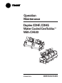
Operation
Maintenance
Duplex CDHF, CDHG
Water Cooled CenTraVac™
With CH530
X39640670030
CDHF-SVU01C-EN
Warnings and
Cautions
Warnings and Cautions
Notice that warnings and cautions
appear at appropriate intervals
throughout this manual. Warnings
are provided to alert installing
contractors to potential hazards that
could result in personal injury or
death, while cautions are designed to
alert personnel to conditions that
could result in equipment damage.
Your personal safety and the proper
operation of this machine depend
upon the strict observance of these
precautions.
NOTICE:
Warnings and Cautions appear at appropriate sections throughout this manual.
Read these carefully.
WARNING – Indicates a potentially hazardous situation which, if not avoided, could result in
death or serious injury.
CAUTION – Indicates a potentially hazardous situation which, if not avoided, may result in
minor or moderate injury. It may also be used to alert against unsafe practices.
CAUTION – Indicates a situation that may result in equipment or property-damage-only accidents.
© 2005 American Standard All rights reserved
CDHF-SVU01C-EN
Contents
Warnings and Cautions
2
General Information
4
Unit Control Panel (UCP)
28
Operator Interface
30
Chilled Water Setpoint
38
Inter Processor Communication (IPC)
51
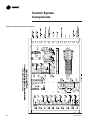
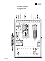
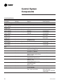
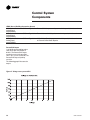
Control System Components
52
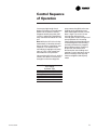
Controls Sequence of Operation
67
Machine Protection and Adaptive Control
72
Unit Startup
89
Unit Shutdown
91
Periodic Maintenance
92
Oil Maintenance
95
Maintenance
97
Forms
CDHF-SVU01C-EN
104
3
General
Information
Literature change
Unit Nameplate
Applicable to CDHF, CDHG
The unit nameplate is located on the
left side of the unit control panel.
The following information is
provided on the unit nameplate.
About this manual
Operation and maintenance
information for models CDHF, CDHG
are covered in this manual. This
includes both 50 and 60 Hz. CDHF
and CDHG centrifugal chillers
equipped with the Tracer CH530
Chiller Controller system. Please note
that information pertains to all three
chiller types unless differences exist
in which case the sections are
broken down by Chiller type as
applicable and discussed separately.
By carefully reviewing this
information and following the
instructions given, the owner or
operator can successfully operate
and maintain a CDHF, or CDHG unit.
If mechanical problems do occur,
however, contact a qualified service
organization to ensure proper
diagnosis and repair of the unit.
1. Serial Number
The unit serial number provides the
specific chiller identity. Always
provide this serial number when
calling for service or during parts
identification..
2. Service Model Number
The service model represents the unit
as built for service purposes . It
identifies the selections of variable
unit features required when ordering
replacements parts or requesting
service.
4. Identifies unit electrical
requirements
Note: Unit-mounted starters are
identified by a separate number
found on the starter.
7. Identifies unit Installation and
Operation and Maintenance manuals
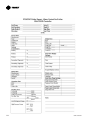
Typical Product Description Block
MODL CDHF
DSEQ 2R
HRTZ 60
TYPE SNGL
EVTM IECU
EVTH 28
EVWC STD
EVWP 2
EVCO VICT
EVWA LELE
CDSZ 032S
CDBS 250
CDWT NMAR
CDPR 150
CDTY STD
TSTY STD
PURG PURE
WCNM SNMP
HHOP NO
GENR NO
ACCY ISLS
HGBP WO
CNIF UCP
SRTY USTR
4
3. Product Coding Block
The CDHF and CDHG models are
defined and built using the product
definition and selection (PDS)
system. This system describes the
product offerings in terms of a
product coding block which is made
up of feature categories and feature
codes. An example of a typical
product code block is given on this
page. The coding block precisely
identifies all characteristics of a unit.
5. Correct operating charges and type
of refrigerant
6. Unit Test Pressures and Maximum
Operating Pressures
8. Drawing numbers for Unit Wiring
Diagrams
NTON 2500
CPKW 142
EVSZ 032S
EVWT NMAR
CDTM IECU
CDWC STD
CDCO VICT
ECTY WEOR
SPKG DOM
GNSL NO
LUBE SNGL
SRRL 207
VOLT 575
REF 123
CPIM 222
TEST AIR
EVBS 280
EVPR 150
CDTH 28
CDWP 2
CDWA LELE
ORSZ 230
OPTI CPDW
SOPT SPSH
AGLT CUL
PNCO TERM
CDHF-SVU01C-EN
General
Information
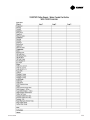
Model Number - An example of a
typical duplex centrifugal chiller
model number is:
CDHF2100AA0BC2552613C0B203B0
B20KJAC1GW40C111340A010
Digit: Description
1st-2nd CD = CenTraVac® Duplex - 2
compressors
3rd H =Direct Drive
4th F = Development Sequence
(F - 2 Stage) (G - 3 Stage)
5th-8th 2100 = Nominal total
compressor tonnage
9th A = Unit Voltage
A = 380V-60Hz-3Ph
B = 440V-60Hz-3Ph
C = 460V-60Hz-3Ph
D = 480V-60Hz-3Ph
E = 575V-60Hz-3Ph
F = 600V-60Hz-3Ph
G = 2300V-60Hz-3Ph
H = 2400V-60Hz 3Ph
J = 3300V-60Hz-3Ph
K = 4160V-60Hz-3Ph
L = 6600V-60Hz-3Ph
M = 380V-50Hz-3Ph
N = 400V-50Hz-3Ph
P = 415V-50Hz-3Ph
R = 3300V-50Hz-3Ph
T = 6000V-50Hz-3Ph
U = 6600V-50Hz-3Ph
10th-11th A0 = Design Sequence
12th B = Compressor Motor
Power, LH Circuit
th
13 C = Compressor Motor
Power, RH Circuit.
Compressor Motor codes:
A = 588 KW
B = 653 KW
C = 745 KW
D = 856 KW
E = 957 KW
F = 1062 KW
G = 1228 KW
H = 433 KW
J = 489 KW
K = 548 KW
L = 621 KW
CDHF-SVU01C-EN
M = 716 KW
N = 799 KW
P = 892 KW
R = 403 KW
S = 453 KW
T = 512 KW
U = 301 KW
V = 337 KW
W = 379 KW
X = 1340 KW
14th-16th 255 = Compressor Impeller
Diameter LH Circuit
17th-19th 261 = Compressor Impeller
Diameter RH Circuit
20th 3 = Evaporator Tube Bundle
Size
1 = 2100 nominal ton
evaporator
2 = 2300 nominal ton
evaporator
3 = 2500 nominal ton
evaporator
4 = 1610 nominal ton
evaporator
5 = 1850 nominal ton
evaporator
21st C = Evaporator Tubes
A = I/E copper, 0.028” wall, 0.75” O.D.
B = I/E copper, 0.035” wall, 0.75” O.D.
C = S/B copper, 0.028” wall, 0.75”
O.D.
D = S/B copper, 0.035” wall, 0.75”
O.D.
E = I/E copper, 0.028” wall, 1.0” O.D.
F = I/E copper, 0.035” wall, 1.0” O.D.
22nd 0 = Not Assigned
23rd B - Evaporator Waterbox
A = 150 psig 1 pass marine
B = 300 psig 1 pass marine
C = 150 psig 1 pass non-marine
D = 300 psig 1 pass non-marine
24th 2 = Evaporator Waterbox
Connection;
1 = Victaulic
2 = Flanged
25th 0 = Not Assigned
26th 3 = Condenser Tube Bundle Size
1 = 2100 nominal ton condenser
2 = 2300 nominal ton condenser
3 = 2500 nominal ton condenser
4 = 1610 nominal ton condenser
5 = 1760 nominal ton condenser
6 = 1900 nominal ton condenser
27th B = Condenser Tubes
A = I/E copper, 0.028” wall, 0.75” O.D.
B = I/E copper, 0.035” wall, 0.75” O.D.
C = S/B copper, 0.028” wall, 0.75”
O.D.
D = S/B copper, 0.035” wall, 0.75”
O.D.
E = I/E copper, 0.028” wall, 1.0” O.D.
F = I/E copper, 0.035” wall, 1.0” O.D.
G = I/E 90/10 CU/NI, 0.035” wall,
0.75” O.D.
28th 0 = Not Assigned
29th B = Condenser Waterboxes
A = 150 psig 1 pass marine
B = 300 psig 1 pass marine
C = 150 psig 1 pass non-marine
D = 300 psig 1 pass non-marine
30th 2 = Condenser Waterbox
Connection;
1 = Victaulic
2 = Flanged
31st 0 = Not Assigned
32nd K = Orifice Size, LH Circuit,
33rd J = Orifice Size, RH Circuit,
Orifice Nominal Tons:
A = 710
B = 790
C = 880
D = 990
E = 1100
F = 1265
G = 1400
H = 1540
K = 1810
J = 1660
L = 1970
M = 2150
N = 1045
P = 1185
R = 1335
T = 1605
U = 1735
5
General
Information
V = 1890
W = 2060
X = 1475
Z = 560 - 3 stage 935 - 2 stage
Y = 500 - 3 stage 835 - 2 stage
1 = 630 - 3 stage 2245 - 2 stage
2 = 800 - 3 stage 2345 - 2 stage
3 = 900 - 3 stage 2450 - 2 stage
4 = 1000 - 3 stage 2560 - 2 stage
5 = 1120 - 3 stage 2675 - 2 stage
6 = 1250
7 = 1600
8 = 1800
9 = 750
th
34 A = Starter Type
A = Star-Delta Unit Mounted
C = Star Delta Remote Mounted
E = X-Line Full Volt Remote Mounted
F = Autotransformer Remote
Mounted
G = Primary Reactor Remote
Mounted
H = X-Line Full Volt Unit Mounted
J = Autotransformer Unit Mounted
K = Primary Reactor Unit Mounted
L = Solid State Unit Mounted
M = Solid State Floor Mounted
N = Solid State Wall Mounted
P = Adaptive Freq. Drive-Unit
Mounted
R = Customer Supplied
35th C = Control Enclosure;
C = Standard
S = Special
th
36 1 = Control: Enhanced Protection;
0 = None
1 = Enhanced protection
40th C = Control: Condenser
Refrigerant Pressure;
0 = None, C = with
41st 1 = Control: Extended Operation;
0 = None
1 = Extended operation
42nd 1 = Chilled Water Reset Outdoor Air Temperature Sensor
0 = None,
1 = Chilled water reset – with outdoor
air temperature sensor,
S = Special
43rd 1 = Control: Operating Status,
0 = None,
1 = Operating Status
44th 1 = Gas Powered Chiller;
0 = No
1 = Yes
45th 3 = Compressor Motor Frame
Size LH Circuit
46th 4 = Compressor Motor Frame
Size RH Circuit
FRAME SIZE CODES: 3 = 440E, 4 =
5000, 5 = 5800, 6 = 5800L, S = Special
47th 0 = Unit Insulation;
0 = None
1 = Insulation package
48th A = Spring Isolators
0 = No
A = Yes
49th 0 = Not Assigned
0 = Not assigned
37th G = Control: Generic BAS;
0 = None
G = Generic BAS
50th 1 = Evaporator & Condenser Size
1 = 210D - 2100,
2 = 250D – 2500,
3 = 250X - 2500 ,
4 = 250M - 2500
38th W = Water Flow Control;
0 = None
W = Water flow control
51st 0 = Special Options
0 = None
S = Special Option
39th 4 = Tracer® Comm. Interface
0 = None, 4 = COMM 4,
5 = COMM 5, S = Special
6
CDHF-SVU01C-EN
General
Information
Commonly Used Acronyms
For convenience, a number of
acronyms are used throughout this
manual. These acronyms are listed
alphabetically below, along with the
“translation” of each:
HVAC = Heating, Ventilating, and Air
Conditioning
IE = Internally-Enhanced Tubes
Control Optional Packages
OPST Operating Status Control
IPC = Interprocessor Communication
GBAS Generic Building Automation
Interface
LBU = La Crosse Business Unit
EXOP Extended Operation
AFD = Adaptive Frequency Drive
LCD = Liquid Crystal Display
ASME = American Society of
Mechanical Engineers
LED = Light Emitting Diode
CDRP Condenser Pressure
Transducer
MAR = Machine Shutdown Auto
Restart (Non-Latching where chiller
will restart when condition corrects
itself.)
TRMM Tracer Communications
CWR Chiller Water reset outdoor
CABS = Auxiliary Condenser TubeBundle S
MMR = Machine Shutdown Manual
Restart (Latching where chiller must
be manually reset.)
CDBS = Condenser Bundle Size
MP = Main Processor
CDSZ = Condenser Shell Size
PFCC = Power Factor Correction
Capacitor
ASHRAE = American Society of
Heating, Refrigerating and Air
Conditioning Engineers
BAS = Building Automation System
CH530 = Tracer CH530 Controller
DV = DynaView™ Clear Language
Display, also know as the Main
Processor (MP)
PSID = Pounds-per-Square-Inch
(differential pressure)
PSIG = Pounds-per-Square-Inch
(gauge pressure)
CWR = Chilled Water Reset
UCP = Unit Control Panel
CWR’ = Chilled Water Reset Prime
LLID = Low Level Intelligent Device
(Sensor, Pressure Transducer, or
Input/output UCP module)
DTFL = Design Delta-T at Full Load
(i.e., the difference between entering
and leaving chilled water
temperatures)
ELWT = Evaporator Leaving Water
Temperature
ENT = Entering Chilled Water
Temperature
WPSR Water pressure sensing
EPRO Enhanced Protection
RLA = Rated Load Amps
RTD = Resistive Temperature Device
Tracer CH530 = Tracer CH530
controller
TOD = Temperature Outdoor
GPM = Gallons-per-minute
HGBP = Hot Gas Bypass
CDHF-SVU01C-EN
7
General
Information
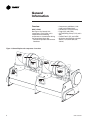
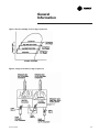
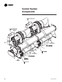
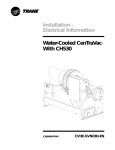
Overview
CDHF - CDHG
See Figure 1 for General Unit
components. Each Chiller unit is
composed of the following
components as viewed when facing
the control panel front side:
• Common Evaporator and Common
Condenser
• Compressors and Motor 1 (Left
hand), and 2 (Right hand)
• Economizers 1(LH), and 2 (RH),
• Purge 1(LH), and 2 (RH),
• Oil Tank/ Refrig. Pump 1 (LH), and 2
(RH),
• Control Panel 1 (LH), and 2 (RH)
• And when specified Unit mounted
Starters 1 (LH) and 2 (RH) (not
shown).
Figure 1. General Duplex unit components - front view
8
CDHF-SVU01C-EN
General
Information
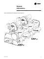
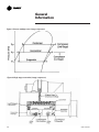
Figure 2. General Duplex unit components (2 stage compressor)
CDHF-SVU01C-EN
9
General
Information
Cooling Cycle
Duplex Chillers have two refrigerant
circuits that operate as their own
independent circuits. These circuits
are discussed as individual chiller
refrigeration units in the following
discussion. The sequence of
operation of the two refrigeration
circuits is discussed in a later
section.
When in the cooling mode, liquid
refrigerant is distributed along the
length of the evaporator and sprayed
through small holes in a distributor
(i.e., running the entire length of the
shell) to uniformly coat each
evaporator tube. Here, the liquid
refrigerant absorbs enough heat from
the system water circulating through
the evaporator tubes to vaporize.
The gaseous refrigerant is then
drawn through the eliminators
(which remove droplets of liquid
refrigerant from the gas) and firststage variable inlet guide vanes, and
into the first stage impeller.
Note: Inlet guide vanes are designed
to modulate the flow of gaseous
refrigerant to meet system capacity
requirements; they also prerotate the
gas, allowing it to enter the impeller
at an optimal angle that maximizes
efficiency at all load conditions.
Compressor 1 or 2 (3 Stage)
Compressed gas from the first-stage
impeller flows through the fixed,
second-stage inlet vanes and into the
second-stage impeller.
10
Here, the refrigerant gas is again
compressed, and then discharged
through the third-stage variable guide
vanes and into the third stage
impeller.
Once the gas is compressed a third
time, it is discharged into the
condenser. Baffles within the
condenser shell distribute the
compressed refrigerant gas evenly
across the condenser tube bundle.
Cooling tower water circulated
through the condenser tubes absorbs
heat from the refrigerant, causing it to
condense. The liquid refrigerant then
passes through orifice plate ‘‘A’’ and
into the economizer.
The economizer reduces the energy
requirements of the refrigerant cycle
by eliminating the need to pass all
gaseous refrigerant through three
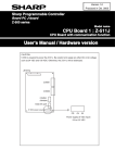
stages of compression. See Figure 3.
Notice that some of the liquid
refrigerant flashes to a gas because
of the pressure drop created by the
orifice plates, thus further cooling the
liquid refrigerant. This flash gas is
then drawn directly from the first
(Chamber A) and second (Chamber
B) stages of the economizer into the
third-and second-stage impellers of
the compressor, respectively.
All remaining liquid refrigerant flows
through another orifice plate ‘‘C’’ to
the evaporator.
Compressor 1 or 2 (2 Stage)
Compressed gas from the first-stage
impeller is discharged through the
second-stage variable guide vanes
and into the second-stage impeller.
Here, the refrigerant gas is again
compressed, and then discharged
into the condenser.
Baffles within the condenser shell
distribute the compressed refrigerant
gas evenly across the condenser
tube bundle. Cooling tower water,
circulated through the condenser
tubes, absorbs heat from the
refrigerant, causing it to condense.
The liquid refrigerant then flows out
of the bottom of the condenser,
passing through an orifice plate and
into the economizer.
The economizer reduces the energy
requirements of the refrigerant cycle
by eliminating the need to pass all
gaseous refrigerant through both
stages of compression. See Figure 6.
Notice that some of the liquid
refrigerant flashes to a gas because
of the pressure drop created by the
orifice plate, thus further cooling the
liquid refrigerant. This flash gas is
then drawn directly from the
economizer into the second-stage
impellers of the compressor.
All remaining liquid refrigerant flows
out of the economizer, passes
through another orifice plate and into
the evaporator.
CDHF-SVU01C-EN
General
Information
Figure 3. Pressure enthalpy curve (3 stage compressor)
Figure 4. 2-stage economizer (3 stage compressor)
CDHF-SVU01C-EN
11
General
Information
Figure 5. Pressure enthalpy curve (2 stage compressor)
Figure 6. Single stage economizer (2 stage compressor)
12
CDHF-SVU01C-EN
General
Information
Overview
Controls Operator Interface
Information is tailored to operators,
service technicians and owners.
When operating a chiller, there is
specific information you need on a
day-to-day basis — setpoints, limits,
diagnostic information, and reports.
When servicing a chiller, you need
different information and a lot more
of it — historic and active
diagnostics, configuration settings,
and customizable control algorithms,
as well as operation settings.
By providing two different tools –
one for daily operation and one for
periodic service — everyone has
easy access to pertinent and
appropriate information.
CDHF-SVU01C-EN
DynaView™ Human Interface
— For the operator
Day-to-day operational information is
presented at the panel. Up to seven
lines of data (English or SI units) are
simultaneously displayed on the ¼
VGA touch-sensitive screen.
Logically organized groups of
information — chiller modes of
operation, active diagnostics,
settings and reports put information
conveniently at your fingertips. See
Operator Interface Section for details.
TechView™ Chiller Service Tool
— For the service technician or
advanced operator
All chiller status, machine
configuration settings, customizable
limits, and up to 60 active or historic
diagnostics are displayed through
the service tool interface. Without
changing any hardware, we give you
access to the latest and greatest
version of Tracer CH530! A new level
of serviceability using the innovative
TechView™ chiller service tool. A
technician can interact with an
individual device or a group of
devices for advanced
troubleshooting. LED lights and their
respective TechView™ indicators
visually confirm the viability of each
device. Any PC that meets the system
requirements may download the
service interface software and Tracer
CH530 updates. For more information
on TechView™ visit your local Trane
Service company, or The Trane
Company’s website at
www.trane.com.
13
General
Information
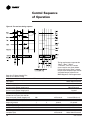
CTV Duplex Sequence Of Operation
This section will provide basic
information on chiller operation for
common events. With
microelectronic controls, ladder
diagrams cannot show today’s
complex logic, as the control
functions are much more involved
than older pneumatic or solid state
controls. Adaptive control algorithms
can also complicate the exact
sequence of operation. This section
and its diagrams attempt to illustrate
common control sequences.
The Sequence of Events diagrams
use the following KEY:
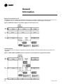
Software States: (Figure 7)
There are five generic states that the
software can be in:
1. Power Up, Stopped, Starting,
Running, Stopping
The large timeline cylinder indicates
the upper level operating mode, as it
would be viewed on DynaView. Text
in Parentheses indicates sub-mode
text as viewed on DynaView. Text
above the timeline cylinder is used to
illustrate inputs to the Main
Processor. This may include User
input to the DynaView Touch pad,
Control inputs from sensors, or
Control Inputs from a Generic BAS.
Boxes indicate Control actions such
as Turning on Relays, or moving the
Inlet Guide Vanes. Smaller cylinders
indicate diagnostic checks, Text
indicates time based functions, Solid
double arrows indicate fixed timers,
Dashed double arrows indicate
variable timers
Timeline Text: (Figures 8-11)
Figure 7. Sequence of operation overview.
14
Power Up Diagram:
The Power up chart shows the
respective DynaView screens during
a power up of the main processor.
This process takes from 30 to 50
seconds depending on the number
of installed Options. On all power
ups, the software model always will
transition through the ‘Stopped’
Software state independent of the last
mode. If the last mode before power
down was ‘Auto’, the transition from
‘Stopped’ to ‘Starting’ occurs, but it
is not apparent to the user.
Software Operation Overview
Diagram:
The Software Operation Overview is
a diagram of the five possible
software states. This diagram can be
thought of as a State Chart, with the
arrows, and arrow text, depicting the
transitions between states.
The text in the circles are the internal
software designations for each State.
The first line of text in the Circles are
the visible top level operating modes
that can be displayed on Dyna View.
The shading of each software state
circle corresponds to the shading on
the timelines that show the state that
the chiller is in.
CDHF-SVU01C-EN
General
Information
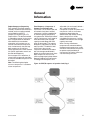
Figure 8. CDHE/F/G sequence of operation: auto to running
This diagram shows the sequence of
operations for a start of the first
compressor on a duplex chiller. The
‘First’ compressor will be determined
by the type of duplex start selected.
Figure 9. CDHE, CDHF, and CDHG sequence of operation: running
Staging Second Compressor On:
This diagram shows the sequence of
operations where the ‘First’
compressor is all ready running, and
the ‘second’ compressor is staged
on. The ‘First’ and ‘Second’
compressor will be determined by
the type of duplex start selected
CDHF-SVU01C-EN
15
General
Information
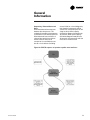
Staging Second Compressor Off:
This diagram shows the sequence of operations where there is no longer a need to run the ‘Second’ compressor, so it
is staged off. The ‘First’ and ‘Second’ compressor will be determined by the type of duplex start selected
Figure 10. CDHE/F/G sequence of operation: staging second compressor off
Satisfied Setpoint:
This diagram shows the sequence of operations where the setpoint has been satisfied, and the last compressor is
staged off.
Figure 11. CDHE, CDHF and CDHG sequence of operation: normal shutdown to stopped and run inhibit
16
CDHF-SVU01C-EN
General
Information
Duplex Compressor Sequencing
Four methods (Two fixed sequence
methods, a balanced start and hour’s
method, and a no staging method)
are provided for order of a
compressor sequencing on CTV
Duplex chillers. The desired method
is selectable at startup via the service
tool. The application can decide to
either balance the wear burden
among the unit’s compressors, to
start the most efficient compressor,
or to simultaneously start and stop
both compressors to minimize
startup pull down time. Each method
has specific applications were it can
be used advantageously.
If one compressor is locked out, in
restart inhibit, or generally not ready
to start, the available compressor will
be started.
Note: The following description
assumes compressor 1 is the down
stream compressor.
CDHF-SVU01C-EN
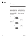
Fixed Sequence – Compressor 1/
Compressor 2 (Default mode)
If the chiller is in the Auto mode and
all interlocks have been satisfied,
compressor 1 will be started based
on the leaving water temperature
rising above the “Differential to Start”
setting. Compressors 2 will stage on
when the overall chiller average
capacity exceeds Stage ON Load
point for 30 seconds. The stage on
load point is adjustable (via service
tool) up to 50%. The default is 40%
which means that a single
compressor would have to load to
80% (the average would be 40%)
before the second compressor starts.
Both compressors will run until
chiller average capacity drops below
Stage off Load point for 30 seconds.
The Stage OFF load point is also
adjustable (via service tool) (default =
30%, range from 0 to 50%).
Compressor 2 will be shut down and
compressor 1 will run until water
temperature drops below the
differential to stop. Before shutting
down, compressor 2 will be
unloaded and compressor 1 will be
loaded to maintain the same average
capacity command.
When running chilled water
temperature at selected conditions,
the downstream compressor usually
will be the most efficient compressor
to operate at part load because
compressors on Duplex chillers are
not sized exactly the same.
Figure 12. CDHF/G sequence of operation: lead 1/lag 2
17
General
Information
Fixed Sequence – Compressor 2 /
Compressor 1
If the chiller is in the Auto mode and
all interlocks have been satisfied,
compressor 2 will be started based
on the leaving water temperature
rising above the “Differential to Start”
setting. Compressors 1 will stage on
when the overall chiller average
capacity exceeds Stage on Load
point for 30 seconds. The stage on
load point is adjustable up to 50%.
The default is 40% which means that
a single compressor would have to
load to 80% (the average would be
40%) before the second compressor
18
starts. Both compressors will run
until chiller average capacity drops
below Stage off Load point for 30
seconds. The stage off load point is
also adjustable. Compressor 1 will
be shut down and compressor 2 will
run until water temperature drops
below the differential to stop. Before
shutting down, compressor 1 will be
unloaded and compressor 2 will be
loaded to maintain the same average
capacity command.
If chilled water reset is used, the
upstream compressor usually will be
the most efficient compressor to
operate at part load. If the leaving
water temperature is reset and the
chiller only needs one compressor,
then the upstream compressor
would be running closer to its
selection point and will be the most
efficient compressor to operate.
Figure 13. CDHE/F/G sequence of operation: lead 2 lag 1
CDHF-SVU01C-EN
General
Information
Sequencing - Balanced Starts and
Hours
When desired to balance the wear
between the compressors. This
method will extend the time between
maintenance on the lead compressor.
When balanced starts and hours is
selected, the compressor with the
fewest starts will start. If that
compressor is unavailable to start
due to a circuit lockout (including
restart inhibit) or a circuit diagnostic,
then the other compressor will be
started. The second compressor will
stage on when chiller capacity
exceeds the Stage on Load point for
30 seconds. When chiller capacity
falls below Stage off Load point for
30 seconds, the compressor with the
most hours will be shut off.
Figure 14. CDHF/G sequence of operation: equalize starts and hours
CDHF-SVU01C-EN
19
General
Information
Simultaneous Compressor Start/
Stop
Both compressors will start in close
succession to minimize the time it
takes for the chiller to reach full load.
Some process applications need the
chiller to start and generate capacity
as fast as possible. This method will
start both compressors, slightly
staggered to prevent doubling of the
current inrush, but will generally
control the chiller as if there were
only one compressor.
If the chiller is in the Auto mode and
all interlocks have been satisfied,
compressor 1 will be started based
on the leaving water temperature
rising above the “Differential to Start”
setting. When compressor 1 is at
speed, compressor 2 will start. Both
compressors will run until water
temperature falls below the
differential to stop, at that time both
compressors will be shut down.
Figure 15. CDHF/G sequence of operation: combined start
20
CDHF-SVU01C-EN
General
Information
Compressor Load Balancing
Duplex chillers with CH530 control
will balance the compressor load by
giving each compressor the same
load command. The load command
will be converted to IGV position that
will be the same on each
compressor.
Balancing compressor load results in
the best overall efficiency and with
both circuits operating with nearly the
same refrigerant pressures.
When both compressors are running
the overall chiller load command will
be split evenly between the two
compressors unless limit control
overrides balancing. When
transitioning between one
compressor operation and twocompressor operation, the load
commands will be actively balanced
at a rate slow enough to minimize
capacity control disturbances
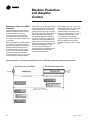
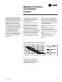
Restart Inhibit
The purpose of restart inhibit feature
is to provide short cycling protection
for the motor and starter.
The operation of the restart inhibit
function is dependent upon two
setpoints. The Restart Inhibit Free
Starts (1-5, 3 default), and the Restart
Inhibit Start to Start Timer (10-30min,
20 default). These settings are
adjustable via the service tool.
Restart Inhibit Free Starts
This setting will allow a number of
rapid restarts equal to its value. If the
number of free starts is set to “1”, this
will allow only one start within the
time period set by the Start to Start
Time Setting. The next start will be
allowed only after the start to start
timer has expired. If the number of
free starts is programmed to “3”, the
control will allow three starts in rapid
succession, but thereafter, it would
hold off on a compressor start until
the Start to Start timer expired.
CDHF-SVU01C-EN
Restart Inhibit Start to Start Time
Setting
This setting defines the shortest
chiller cycle period possible after the
free starts have been used. If the
number of free starts is programmed
to “1”, and the Start to Start Time
Setting is programmed to 20
minutes, then the compressor will be
allowed one start every 20 minutes.
The start-to-start time is the time from
when the motor was commanded to
energize to when the next command
to enter prestart is given.
Clear Restart Inhibit
A Clear Restart Inhibit “button” is
provided within Settings; Manual
Override on the DynaView display.
This provides a way for an operator
to allow a compressor start when
there is a currently active Restart
Inhibit that is prohibiting such a start.
The “button” press will have no
other function than to remove the
restart inhibit if there is one active. It
does not change the count of any
internal restart inhibit timers or
accumulators.
The restart inhibit function, setpoints
and clear features exist for each
compressor and operate
independently of other compressors
on that chiller.
During the time the start is inhibited
due to the start-to-start timer, the
DynaView shall display the mode
‘Restart Inhibit’ and the also display
the time remaining in the restart
inhibit.
A “Restart Inhibit Invoked” warning
diagnostic will exist when the
attempted restart of a compressor is
inhibited.
21
General
Information
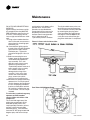
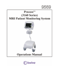
Oil and Refrigerant Pump
Compressor Lubrication System A schematic diagram of the
compressor lubrication system is
illustrated in Figure 16. (This can be
applied to circuit 1 or 2.)
Oil is pumped from the oil tank (by a
pump and motor located within the
tank) through an oil pressureregulating valve designed to maintain
a net oil pressure of 18 to 22 psid. It
is then filtered and sent to the oil
cooler located in the economizer and
on to the bearings. From the
bearings, the oil drains back to the
manifold under the motor and then
on to the oil tank.
WARNING
Surface Temperatures!
MAY EXCEED 150°F. Use caution
while working on certain areas of
the unit, failure to do so may result
in death or personal injury.
22
To ensure proper lubrication and
prevent refrigerant from condensing
in the oil tank, a 750-watt heater is
immersed in the oil tank and is used
to warm the oil while the unit is off.
When the unit starts, the oil heater is
de-energized. This heater energizes
as needed to maintain 140° to 145° F
(60-63°C) when the chiller is not
running.
When the chiller is operating, the
temperature of the oil tank is typically
115° to 160°F (46-72°C). The oil return
lines from the thrust and journal
bearings, transport oil and some seal
leakage refrigerant. The oil return
lines are routed into a manifold
under the motor. Gas flow exits the
top of the manifold and is vented to
the Evaporator.
Note: A vent line solenoid is not
needed with the refrigerant pump. Oil
exits the bottom of the manifold and
returns to the tank. Separation of the
seal leakage gas in the manifold
keeps this gas out of the tank.
A dual eductor system is used to
reclaim oil from the suction cover
and the evaporator, and deposit it
back into the oil tank. These eductors
use high pressure condenser gas to
draw the oil from the suction cover
and evaporator to the eductors and
then discharged into the oil tank. The
evaporator eductor line has a shut off
valve mounted by the evaporator and
ships closed. Open two turns if
necessary.
Liquid refrigerant is used to cool the
oil supply to both the thrust bearing
and journal bearings. On refrigerant
pump units the oil cooler is located
inside the economizer and uses
refrigerant passing from the
condenser to evaporator to cool the
oil. Oil leaves the oil cooler and
flows to both the thrust and journal
bearings.
Motor Cooling System
Compressor motors are cooled with
liquid refrigerant, see Figure 16.
The refrigerant pump is located on
the front of the oil tank (motor inside
the oil tank). The refrigerant pump
inlet is connected to the well at the
bottom of the condenser. The
connection is on the side where a
weir assures a preferential supply of
liquid. Refrigerant is delivered to the
motor via the pump. Motor
refrigerant drain lines are routed to
the condenser.
CDHF-SVU01C-EN
General
Information
Figure 16. Oil refrigerant pump - circuit 1 or 2
CDHF-SVU01C-EN
23
General
Information
Base Loading Control
Algorithm:
This feature allows an external
controller to directly modulate the
capacity of the chiller. It is typically
used in applications where virtually
infinite sources of evaporator load
and condenser capacity are available
and it is desirable to control the
loading of the chiller. Two examples
are industrial process applications
and cogeneration plants. Industrial
process applications might use this
feature to impose a specific load on
the facility’s elecrical system.
Cogeneration plants might use this
feature to balance the system’s
heating, cooling and electrical
generation.
All chiller safeties and adaptive
control functions are in full effect
when Base Loading control is
enabled. If the chiller approaches full
current, the evaporator temperature
drops too low, or the condenser
pressure rises too high, Tracer CH530
Adaptive Control logic limits the
loading of the chiller to prevent the
chiller from shutting down on a
safety limit. These limits may prevent
the chiller from reaching the load
requested by the Base Loading
signal.
Base Loading Control is basically a
variation of the current limit
algorithm. During base loading, the
leaving water control algorithm
provides a load command every 5
seconds. The current limit routine
may limit the loading when the
current is below setpoint. When the
current is within the deadband of the
setpoint the current limit algorithm
holds against this loading command.
24
If the current exceeds the setpoint,
the current limit algorithm unloads.
The “Capacity Limited By High
Current” message normally
displayed while the current limit
routine is active is suppressed while
base loading.
Base loading can occur via Tracer,
External signal, or front panel.
Tracer Base Loading:
Current Setpoint Range:
(20 - 100) percent RLA
Requires Tracer and Optional Tracer
Communications Module (LLID)
The Tracer commands the chiller to
enter the base load mode by sending
the base load mode request. If the
chiller is not running, it will start
regardless of the differential to start
(either chilled water or hot water). If
the chiller is already running, it will
continue to run regardless of the
differential to stop (either chilled
water or hot water), using the base
load control algorithm. While the unit
is running in base loading, it will
report that status back to the Tracer
by setting “Base Load Status = true”
in the Tracer Status Byte. When the
Tracer removes the base load mode
request (sets the bit to 0). The unit
will continue to run, using the
normal chilled or hot water control
algorithm, and will turn off, only
when the differential to stop has been
satisfied.
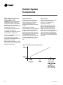
External Base Loading:
Current Setpoint Range:
(20 - 100) percent RLA
The UCP accepts 2 inputs to work
with external base loading. The
binary input is at 1A18 Terminals J2-1
and J2-2 (Ground) which acts as a
switch closure input to enter the
base-loading mode. The second
input, an analog input, is at 1A17
terminals J2 – 1 and 3 (Ground)
which sets the external base loading
setpoint, and can be controlled by
either a 2-10Vdc or 4-20ma Signal. At
startup the input type is configured.
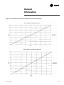
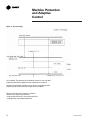
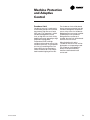
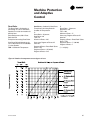
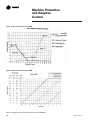
The graphs in Figure 13 show the
relationship between input and
percent RLA. While in base loading
the active current limit setpoint is set
to the Tracer or external base load
setpoint, providing that the base load
setpoint is not equal to 0 (or out of
range). If it is out of range, the front
panel current limit setpoint is used.
During base loading, all limits are
enforced with the exception of
current limit. The human interface
displays the message “Unit is
Running Base Loaded”. Hot Gas
Bypass is not run during base
loading. If base loading and ice
making are commanded
simultaneously, ice making takes
precedence.
An alternative and less radical
approach to Base Loading indirectly
controls chiller capacity. Artifically
load the chiller by setting the chilled
water setpoint lower than it is
capable of achieving. Then, modify
the chiller’s load by adjusting the
current limit setpoint. This method
provides greater safety and control
stability in the operation of the chiller
because it has the advantage of
leaving the chilled water temperature
control logic in effect. The chilled
water temperature control logic
responds quicker to dramatic system
changes, and can limit the chiller
loading prior to reaching an Adaptive
Control limit point.
CDHF-SVU01C-EN
General
Information
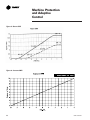
Figure 17. Base loading with external mA input and with external voltage input
CDHF-SVU01C-EN
25
General
Information
Ice Machine Control
UCP provides a service level “Enable
or Disable” menu entry for the Ice
Building feature when the Ice
Building option is installed. Ice
Building can be entered from “Front
Panel”, or if hardware is specified the
UCP will accept either an isolated
contact closure (1A19 Terminals J2-1
and J2-2 (Ground) ) or a remote
communicated input (Tracer) to
initiate the ice building mode where
the unit runs fully loaded at all times.
Ice building will be terminated either
by opening the contact or based on
entering evaporator fluid
temperature. UCP will not permit the
Ice Building mode to be entered
again until the unit is switched to the
Non-ice building mode and back into
the ice building mode. It is not
acceptable to reset the chilled water
setpoint low to achieve a fully loaded
compressor. When entering icebuilding the compressor will be
loaded at its maximum rate and
when leaving ice building the
compressor will be unloaded at its
maximum rate. While loading and
unloading the compressor, all surge
detection will be ignored. While in
the ice building mode, current limit
setpoints less than the maximum will
be ignored. Ice Building can be
terminated by one of the following
means:
1. Front panel disable.
2. Opening the external Ice. Contacts/
Remote communicated input
(Tracer).
3. Satisfying an evaporator entering
fluid temperature setpoint. (Default
is 27°F)
4. Surging for 7 minutes at full open
IGV.
26
Figure 18. Sequence of operation: ice making: running to ice making
Figure 19. Sequence of operation: ice making: stopped to ice to ice building
complete
CDHF-SVU01C-EN
General
Information
Hot Water control
Occasionally CTV chillers are
selected to provide heating as a
primary mission. With hot water
temperature control, the chiller can
be used as a heating source or
cooling source. This feature provides
greater application flexibility. In this
case the operator selects a hot water
temperature and the chiller capacity
is modulated to maintain the hot
water setpoint. Heating is the primary
mission and cooling is a waste
product or is a secondary mission.
This type of operation requires an
endless source of evaporator load
(heat), such as well or lake water. The
chiller has only one condenser.
Note: Hot water temperature control
mode does not convert the chiller to
a heat pump. Heat pump refers to the
capability to change from a coolingdriven application to a heating-driven
application by changing the
refrigerant path on the chiller. This is
impractical for centrifugal chillers as
it would be much easier to switch
over the water side.
This is NOT heat recovery. Although
this feature could be used to recover
heat in some form, there’s not a
second heat exchanger on the
condenser side.
CDHF-SVU01C-EN
The DynaView™ Main Processor
provides the hot water temperature
control mode as standard. The
leaving condenser water temperature
is controlled to a hot water setpoint
between 80 and 140°F (26.7 to 60°C)
The leaving evaporator water
temperature is left to drift to satisfy
the heating load of the condenser. In
this application the evaporator is
normally piped into a lake, well, or
other source of constant temperature
water for the purpose of extracting
heat.
In hot water temperature control
mode all the limit modes and
diagnostics operate as in normal
cooling with one exception; The
leaving condenser water temperature
sensor is an MMR diagnostic when
in hot water temperature control
mode. (It is an informational warning
in the normal cooling mode.)
In the hot water temperature control
mode the differential-to-start and
differential-to-stop setpoints are used
with respect to the hot water setpoint
instead of with the chilled water
setpoint.
UCP provides a separate entry at the
DV to set the hot water setpoint.
Tracer is also able to set the hot
water setpoint. In the hot water mode
the external chilled water setpoint is
the external hot water setpoint; that
is, a single analog input is shared at
the 1A16 –J2-1 to J2-3 (ground)
An external binary input to select
external hot water control mode is on
the EXOP OPTIONAL module 1A18
terminals J2-3 to J2-4 (ground). Tracer
also has a binary input to select
chilled water control or hot water
temperature control.
There is no additional leaving hot
water temperature cutout; the HPC
and condenser limit provide for high
temperature and pressure protection.
In hot water temperature control the
softloading pulldown rate limit
operates as a softloading pullup rate
limit. The setpoint for setting the
temperature rate limit is the same
setpoint for normal cooling as it is
for hot water temperature control.
The hot water temperature control
feature is not designed to run with
HGBP, AFD, or ice making.
The factory set PID tuning values for
the leaving water temperature control
are the same settings for both normal
cooling and hot water temperature
control.
27
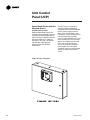
Unit Control
Panel (UCP)
Control Panel Devices and Unit
Mounted Devices
Unit Control Panel (UCP)
Safety and operating controls are
housed in the unit control panel, the
starter panel and the purge control
panel. The UCP ‘s operator interface
and main processor is called the
DynaView™ (DV) and is located on
the UCP door. (See Operators
interface section for detailed
information)
The UCP houses several other
controls modules called panel
mounted LLID (Low Level Intelligent
Device), power supply, terminal
block, fuse, circuit breakers, and
transformer. The IPC (Interprocessor
communication) bus provides
communication between LLID’s and
the main processor. Unit mounted
devices are called frame mounted
LLID’s and can be temperature
sensors or pressure transducers,
vane actuator. These and other
functional switches provide analog
and binary inputs to the control
system.
Figure 20. Left control panel
28
CDHF-SVU01C-EN
Unit Control
Panel (UCP)
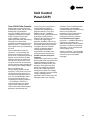
Tracer CH530 Chiller Controller
Revolutionary control of the chiller,
chilled water system, and your entire
building with unprecedented
accuracy, reliability, efficiency, and
support for maintenance using the
chiller’s PC-based service tool.
Chiller reliability is all about
producing chilled water and keeping
it flowing, even when facing
conditions that ordinarily would shut
down the chiller — conditions that
often happen when you need cooling
the most.
Tracer CH530’s Main Processor,
DynaView™, is fast and keeps the
chiller online whenever possible.
Smart sensors collect three rounds of
data per second, 55 times the data
collection speed of its predecessor.
Each device (a sensor) has its own
microprocessor that simultaneously
converts and accurately calibrates its
own readings from analog to digital.
Because all devices are
communicating digitally with the
DynaView™ main processor, there is
no need for the main processor to
convert each analog signal one at a
time. This distributed logic allows
the main processor to focus on
responding to changing conditions
— in the load, the machine, its
ancillary equipment, or its power
supply. Tracer CH530 constantly
receives information about key data
parameters, temperatures and
CDHF-SVU01C-EN
current. Every five seconds then a
multiple objective algorithm
compares each parameter to its
programmed limit. The chiller’s
Adaptive Control™ capabilities
maintain overall system performance
by keeping its peak efficiency.
Whenever the controller senses a
situation that might trigger a
protective shutdown, it focuses on
bringing the critical parameter back
into control. When the parameter is
no longer critical, the controller
switches its objective back to
controlling the chilled water
temperature, or to another more
critical parameter should it exist.
Variable water flow through the
evaporator
Chilled-water systems that vary water
flow through chiller evaporators have
caught the attention of engineers,
contractors, building owners, and
operators. Varying the water flow
reduces the energy consumed by
pumps, while requiring no extra
energy for the chiller. This strategy
can be a significant source of energy
savings, depending on the
application. With its faster and more
intelligent response to changing
conditions, Tracer CH530 water flow
sensing option accommodates
variable evaporator water flow and its
effect on the chilled water
temperature. These improvements
keep chilled water flowing at a
temperature closer to its setpoint.
User-defined language support
DynaView™ is capable of displaying
English text or one of the two
alternate languages that are stored in
DynaView™ at one time. Switching
languages is simply accomplished
from a settings menu.
Similarly, TechView™ accommodates
a primary and a secondary language
from the same list of available
languages.
29
Operator
Interface
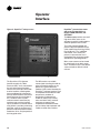
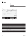
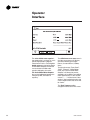
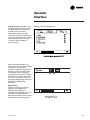
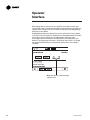
Figure 21. DynaView™ main processor
DynaView™ presents three menu
tabs across the top which are
labeled “MAIN, REPORTS, and
SETTINGS”.
The Main screen provides an overall
high level chiller status so the
operator can quickly understand the
mode of operation of the chiller.
The Chiller Operating Mode will
present a top level indication of the
chiller mode (Auto, Running, Inhibit,
Run Inhibit, etc.) The “additional
information” icon (arrow) will
present a subscreen that lists in
further detail the subsystem modes.
(See Machine Operating Modes.)
Main screen content can be viewed
by selecting the up or down arrow
icons. The Main screen is the default
screen and after an idle time of 30
minutes.
The DynaView™ (DV) Operator
Interface contains the “Main
Processor (MP)” and is mounted on
the unit control panel front door
where it communicates commands
to other modules, collecting data,
status and diagnostic information
from the other modules over the IPC
(Inter Processor Communications)
link. The Main Processor (MP)
software controls water flows by
starting pumps and sensing flow
inputs, establishes a need to heat or
cool, performs pre-lube, performing
post-lube, starts the compressor(s),
performs water temperature control,
establishes limits, and pre-positions
the inlet guide-vanes.
30
The MP contains non-volatile
memory both checking for valid set
points and retaining them on any
power loss. System data from
modules (LLID) can be viewed at the
DynaView™ operator interface. Such
as evaporator and condenser water
temperatures, outdoor air
temperature, evaporator and
condenser water pump control,
status and alarm relays, external
auto-stop, emergency stop,
evaporator and condenser water
pressure drops and evaporator and
condenser water flow switches.
CDHF-SVU01C-EN
Operator
Interface
DynaView™ (DV) is the operator
interface of the Tracer CH530 control
system utilized on the CTV machine.
The DynaView™ enclosure is 9.75"
wide, 8” high and 1.6” deep. The
DynaView™ display is approximately
4” wide by 3” high. Features of the
display include a touch screen and
long life LED backlight. This device is
capable of operating in 0 - 95 percent
relative humidity (non-condensing),
and is designed and tested with UV
considerations consistent with an
outdoor application in direct
sunlight. The enclosure includes a
weather tight connection means for
the RS232 service tool connection.
Touch screen key functions are
determined completely in the
software and change depending
upon the subject matter currently
being displayed. The user operates
the touch sensitive buttons by
touching the button of choice. The
selected button is darkened to
indicate it is the selected choice. The
advantage of touch sensitive buttons
is that the full range of possible
choices as well as the current choice
is always in view.
CDHF-SVU01C-EN
Spin values (up or down) are a
graphical user interface model used
to allow a continuously variable
setpoint, such as leaving water
setpoint to be changed. The value
changes by touching the increment
or decrement arrows.
Action buttons are buttons that
appear temporarily and provide the
operator with a choice such as Enter
or Cancel. The operator indicates his
choice by touching the button of
choice. The system then takes the
appropriate action and the button
typically disappears.
DynaView™ consists of various
screens, each meant to serve a
unique purpose of the machine being
served. Tabs are shown across the
top of the display. The user selects a
screen of information by touching the
appropriate tab. The folder that is
selected will be brought to the front
so it’s contents are visable
The main body of the screen is used
for description text, data, setpoints,
or keys (touch sensitive areas) The
double up arrows cause a page by
page scroll either up or down. The
single arrow causes a line by line
scroll to occur. At the end of the
screen, the appropriate scroll buttons
will disappear. Wrap around will not
occur.
The bottom of the screen is the
persistent area. It is present in all
screens and performs the following
functions. The left circular area is
used to reduce the contrast and
viewing angle of the display. The
right circular area is used to increase
the contrast and viewing angle of the
display. The contrast control will be
limited to avoid complete “light” or
complete “dark”, which would
potentially confuse an unfamiliar
user to thinking the display was
malfunctioning.
31
Operator
Interface
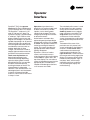
The Auto and Stop keys are used to
put the unit into the auto or stop
modes. Key selection is indicated by
being darkened (reverse video).
The Alarms button is to the right of
the Stop key. The Alarms button
appears only when alarm information
is present. The alarm blinks to draw
attention to the shutdown diagnostic
condition. Blinking is defined as
normal versus reverse video.
Pressing on the Alarms button takes
you to the corresponding screen.
Persistent keys, horizontal at the
bottom of the display, are those keys
that must be available for operation
regardless of the screen currently
being displayed. These keys are
critical for machine operation. The
Auto and Stop keys will be
presented as radio buttons within the
persistent key display area. The
32
selected key will be dark. The chiller
will stop when the Stop key is
touched, entering the stop sequence.
Pressing the “Immediate Stop”
button will cause the chiller to stop
immediately.
The AUTO and STOP, take
precedence over the ENTER and
CANCEL keys. (While a setting is
being changed, AUTO and STOP
keys are recognized even if ENTER or
CANCEL has not been pressed.
Selecting the Auto key will enable the
chiller for active cooling ( if no
diagnostic is present.)
How It Works
This new feature will be activated
after the service tech sets a variable
shut down timer in TechView to be
greater that 0 seconds and up to 20
seconds (i.e. 0 < Timer ± 20). Then,
when the user presses the ‘STOP’
button on the DynaView display and
initiates a chiller shutdown, a
window will now appear that
displays the “Unit Stop Information
Screen” as shown below.
TechView service tool is utilized to
enable this feature.
Chiller Stop Prevention/Inhibit
Feature
A new chiller “Stop prevention/
inhibit” feature allows a user to
prevent an inadvertent chiller stop
from the DynaView screen for those
chillers which are solely controlled
by the CH530.
CDHF-SVU01C-EN
Operator
Interface
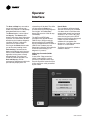
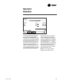
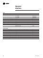
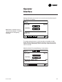
Figure 22
The machine-operating mode
indicates the operational status of the
chiller. A subscreen with additional
mode summary information will be
provided. When the user scrolls
down the screen the Machine
Operation Mode will remain
stationary
On DynaView™, the user will be
presented with a single line of text
that represents the ‘top-level’
operating state of the machine. These
top-level modes are shown in the
table below. Additional information (if
it exists) regarding the machine
operating state will be available to
the user by selecting the “additional
information” button (double right
arrow) next to the top-level operating
mode. These sub-level modes are
shown in the table at left.
A general description of the top level modes is show in the following table.
Top Level Mode
Description
Stopped
Unit inhibited from running and will require
user action to go to Auto.
Run Inhibit
Unit inhibited from running by Tracer,
External BAS, or an Auto Reset diagnostic.
Auto
Unit determining if there is a need to run.
Waiting To Start
Unit waiting for tasks required prior to
compressor start to be completed.
Starting Compressor
Unit is starting compressor.
Running
Compressor is running with no limits in
effect.
Running – Limit
Compressor is running with limit in effect.
Preparing To Shutdown
Unit is closing inlet guide vanes prior to
compressor shutdown.
Shutting Down
Compressor has been stopped and unit is
performing shutdown tasks.
CDHF-SVU01C-EN
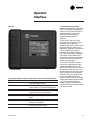
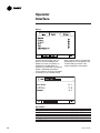
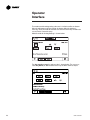
The TOP LEVEL MODE is the text
seen on the single top level chiller
system operating mode line. The
SUB LEVEL MODE is the text seen on
the operating mode sub-menu. The
operating mode sub-menu may have
up to six (6) lines of text displayed.
The BAS CODE is the code that will
be sent via COMM4 to the Tracer
Summit system as the chiller system
mode. Note that each top level mode
may contain multiple sub level
modes. In general, the BAS CODE
will reflect the top level mode and not
the sub level mode.
33
Operator
Interface
Figure 23
Top Level Mode
SYSTEM RESET
Stopped
Stopped
Stopped
Run Inhibit
Run Inhibit
Run Inhibit
Run Inhibit
Auto
Auto
Auto
Auto
Waiting To Start
Waiting To Start
Waiting To Start
34
Sub Level Mode
Boot & Application software part number, self-test, and
configuration validity screens will be present.
Local Stop
Panic Stop
Diagnostic Shutdown – Manual Reset
Ice Building Is Complete
Tracer Inhibit
External Source Inhibit
Diagnostic Shutdown – Auto Reset
Waiting For Evaporator Water Flow
Waiting For A Need To Cool
Waiting For A Need To Heat
Power Up Delay Inhibit:
MIN:SEC
Waiting For Condenser Water Flow
Establishing Oil Pressure
Pre-Lubrication Time:
MIN:SEC
Reference
BAS Code
NA
00
00
00
100
100
100
100
58
58
58
58
70
70
70
CDHF-SVU01C-EN
Operator
Interface
Top Level Mode
Waiting To Start
Waiting To Start
Waiting To Start
Waiting To Start
Waiting To Start
Starting Compressor
Running
Running
Running
Running
Running
Running
Running
Running
Running – Limit
Running – Limit
Running – Limit
Running – Limit
Running – Limit
Running – Limit
Preparing To
Shutdown
Shutting Down
Shutting Down
Shutting Down
CDHF-SVU01C-EN
Sub Level Mode
Motor Temperature Inhibit: Motor Temperature / Inhibit Temperature
Restart Time Inhibit: MIN:SEC
High Vacuum Inhibit: Oil Sump Press / Inhibit Press
Low Oil Temperature Inhibit: Oil Temperature / Inhibit Temperature
Waiting For Starter To Start: MIN:SEC
There is no sub mode displayed
There is no sub mode displayed
Hot Water Control
Surge
Base Loaded
Ice Building
Ice To Normal Transition
Current Control Soft Loading
Capacity Control Soft Loading
Current Limit
Phase Unbalance Limit
Condenser Pressure Limit
Evaporator Temperature Limit
Minimum Capacity Limit
Maximum Capacity Limit
Closing IGV:
IGV Position %
Post-Lubrication Time:
MIN:SEC
Evaporator Pump Off Delay:
MIN:SEC
Condenser Pump Off Delay:
MIN:SEC
Reference
BAS Code
70
70
70
70
70
72
74
74
74
74
74
74
74
74
75
75
75
75
75
75
7E
7E
7E
7E
35
Operator
Interface
Main Screen
The main screen is provides “an
overall view“ of the chiller
performance in addition to the main
and sub operating modes. The table
below indicates other items found ,
when specified by options, that can
be scrolled to via the up or down
arrows.
Main Screen Data Fields Table
Description
1. Chiller Mode (>> submodes)
2. Circuit 1 Mode (>> submodes)
3. Circuit 2 Mode (>> submodes)
4. Evap Ent/Lvg Water Temp
5. Cond Ent/Lvg Water Temp
6. Active Chilled Water Setpoint (>>source)
7. Active Hot Wtr Setpoint (>>source)
8. Active Current Limit Setpoint (>>source)
9. Active Base Loading Setpoint (>>source)
10. Circuit 1 Purge Mode (status, i.e. on, off,
adaptive, auto))
11. Circuit 2 Purge Mode (status, i.e. on, off,
adaptive, auto))
12. Approx Chiller Capacity
13. Active Ice Termination Setpoint (>>source)
14. Software Version
Units
Resolution
Dependencies
F/C
F/C
F/C
F/C
% RLA
%
See modes in
purge manual
See modes in
purge manual
Tons / kW
F/C
0.1
0.1
0.1
0.1
1
1
Emum
If in heat installed
Chiller Operating Mode
The machine-operating mode
indicates the operational status of the
chiller. A subscreen with additional
mode summary information will be
provided by selection of an
additional information icon (>>). The
operating mode lines will remain
stationary while the remaining status
items scroll with the up/down arrow
keys.
36
If enabled
Enum
XXX
0.1
0.XX
If option installed
If option installed
Circuit Operating Mode
The circuit-operating modes indicate
the operational status of the circuits.
A subscreen with additional mode
summary information will be
provided by selection of an
additional information icon (>>). The
operating mode lines will remain
stationary while the remaining status
items scroll with the up/down arrow
keys.
CDHF-SVU01C-EN
Operator
Interface
Diagnostic Screen
The diagnostic screen is accessible
by touching the Alarms enunciator.
When an alarm is present, the alarm
enunciator is present next to the Stop
key. A flashing “alarm” indicates a
machine shutdown and a non
flashing “alarm” indicates an
informational message.
Machine shutdowns can be of two
types:
Latching - Machine Shutdown
Manual Reset Required (MMR)
or
Non-Latching - Machine Shutdown
Auto Reset (MAR)
Latching (MMR) require corrective
action and manual reset.
Non-Latching (MAR) will restart
automatically when condition
corrects itself.
There are over 200 potential
messages, too numerous to
incorporate in this manual.
The reason for all diagnostics must
be determined and corrected. Do not
reset and restart the chiller as this
can cause a repeat failure. Contact
local Trane Service for assistance as
necessary.
After corrective action, the chiller can
be reset and/or restarted. In the case
of “Unit Shutdown - Reset Required”
diagnostic types, the chiller will have
to be manually reset through the
Diagnostics alarm menu.
When reset they become historic and
viewable via the service tool
TechView.
Performing a Reset All Active
Diagnostics will reset all active
diagnostics regardless of type,
machine or refrigerant circuit.
A Manual Override indicator (shares
space with the Alarms key) alerts the
operator to the presence of a manual
override. An Alarm will take
precedence over any manual
override, until the reset of active
alarms, at which point the Manual
indicator would reappear if such an
override exists.
Temperature settings can be
expressed in F or C, depending on
Display Units settings.
Dashes (“- - - -”) appearing in a
temperature or pressure report,
indicates that the value is invalid or
not applicable.
The languages for DynaView™ will
reside in the main processor. The
main processor will hold three
languages, English, and two alternate
languages. The service tool
(TechView™) will load the main
processor with user selected
languages from a list of available
translations. Whenever possible,
complete words will be used on the
persistent keys as described.
Up to ten active diagnostics can be
displayed if required.
CDHF-SVU01C-EN
37
Operator
Interface
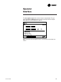
The active chilled water setpoint is
the setpoint that is currently in use. It
will be displayed to 0.1 degrees
Fahrenheit or Celsius. Touching the
double arrow to the left of the Active
Chilled Water Setpoint will take the
user to the active chilled water
setpoint arbitration sub-screen.
The Active Chilled Water Setpoint
the result of arbitration between the
front panel, BAS, and external
setpoints,
The chilled water reset status area in
the right most column will display
one of the following messages:
Return, Constant Return, Outdoor,
None
The left column text “Front Panel”,
“BAS”, “External”, Chilled Water
Reset, and “Active Chilled Water
Setpoint” will always be present
regardless of installation or enabling
those optional items. In the second
column “- - - -” will be shown if that
option is Not Installed, otherwise the
current setpoint from that source will
be shown.
The “Back” button provides
navigation back to the chiller screen.
38
CDHF-SVU01C-EN
Operator
Interface
The active current limit setpoint is
the current limit setpoint that is
currently in use. It will be displayed
in percent RLA. Touching the double
arrow to the left of the Active Current
Limit Setpoint will take the user to
the active current limit setpoint subscreen. The active current limit
setpoint is that setpoint to which the
unit is currently controlling. It is the
result of arbitration between the front
panel, BAS, and external setpoints.
CDHF-SVU01C-EN
The left column text “Front Panel”,
“BAS”, “External”, and “Active
Current Limit Setpoint” will always
be present regardless of installation
or enabling those optional items. In
the second column “- - - -” will be
shown if that option is Not Installed,
otherwise the current setpoint from
that source will be shown. The
“Back” button provides navigation
back to the chiller screen.
Note: This is the same for other
setpoints in the “Main” menu.
39
Operator
Interface
Reports
To aid in comparing the status of
both circuits, the heading on the
Reports list screen has buttons as
indicated in the table above (i.e.,
System, Ckt1, and Ckt2). The selected
button is darkened, presented in
reverse video, or some how changed
to indicate it is the selected choice.
Report Menu
Description
1. Evaporator
2. Condenser
3. Compressor
4. Motor
5. Purge
6. ASHRAE Chiller Log
40
When a report screen is selected, the
appropriate circuit is displayed in the
screen heading as shown in the
sample evaporator screen below:
Heading Buttons
System, Ckt 1, Ckt 2
System, Ckt 1, Ckt 2
Ckt 1, Ckt 2
Ckt 1, Ckt 2
Ckt 1, Ckt 2
System, Ckt 1, Ckt 2
CDHF-SVU01C-EN
Operator
Interface
Report name: System Evaporator
Description
1. Evap Entering Water Temp
2. Evap Leaving Water Temp
3. Evap Water Flow Switch Status
4. Evap Differential Wtr Press
5. Approx Evap Water Flow
6. Approx Chiller Capacity
Resolution
+ or – XXX.X
+ or – XXX.X
(Flow, No Flow)
XXX.X
XXXX
XXXX
Units
Temperature
Temperature
Dependencies
Diff Pressure
Flow
Tons
If option installed
If option installed
If option installed
Report name: Circuit Evaporator
Description
1. Evap Sat Rfgt Temp
2. Evap Rfgt Pressure
3. Evap Approach Temp
Resolution
+ or – XXX.X
XXX.X
+ or – XXX.X
Units
Temperature
Pressure
Temperature
Dependencies
Report name: System Condenser
Description
1. Cond Entering Water Temp
2. Cond Leaving Water Temp
3. Cond Water Flow Switch Status
4. Cond Differential Wtr Press
5. Approx Cond Water Flow
6. Outdoor Air Temperature
Resolution
+ or – XXX.X
+ or – XXX.X
(Flow, No Flow)
XXX.X
XXXX
+ or – XXX.X
Units
Temperature
Temperature
Dependencies
Diff Pressure
Flow
Temperature
If option installed
If option installed
If option installed
Report name: Circuit Condenser
Description
1. Cond Sat Rfgt Temp
2. Cond Rfgt Pressure
3. Cond Approach Temp
Resolution
+ or – XXX.X
XXX.X
+ or – XXX.X
Units
Temperature
Pressure
Temperature
Dependencies
Note: Approach temperatures shown are the mathematical difference between the chiller leaving water temperature and
the corresponding saturated refrigerant temperature of same circuit. When one compressor is operational the approach
value will be similar to those values found on single compressor models. However when both compressors are
operating, the upstream compressor circuits approach will be the mathematical difference of the upstream chillers
refrigerant temperature and the leaving water temperature after the down stream chillers circuit. Therefore the approach
of the upstream circuit will be a negative number in many instances, when both compressors are operating.
CDHF-SVU01C-EN
41
Operator
Interface
Report name: System ASHRAE Chiller Log
Description
Resolution
1. Current Time/Date
XX:XX mmm dd, yyyy
2. Chiller Mode:
3. Active Chilled Water Setpoint:
XXX.X
4. Active Current Limit Setpoint:
XXX
5. Refrigerant Type:
6. Refrigerant Monitor:
XXX.X
7. Evap Entering Water Temp:
XXX.X
8. Evap Leaving Water Temp:
XXX.X
9. Evap Water Flow Switch Status:
10. Evap Differential Wtr Press:
XXX.X
11. Approx Evap Water Flow:
XXX.X
12. Approx Chiller Capacity:
XXXX
13. Cond Entering Water Temp:
XXX.X
14. Cond Leaving Water Temp:
XXX.X
15. Cond Water Flow Switch Status:
16. Cond Differential Wtr Press:
XXX.X
17. Approx. Cond Water Flow:
XXXX
Units
Date / Time
Enum
Temperature
% RLA
Enum
PPM
Temperature
Temperature
Enum
Diff Pressure
GPM/LPM
Capacity
Temperature
Temperature
Enum
Pressure
Flow
Report name: Circuit ASHRAE Chiller Log
Description
Resolution
1. Circuit Operating Mode:
2. Amps L1 L2 L3
XXXX
Units
Enum
Amps
3. Volts AB BC CA
4. Purge Daily Pumpout –24 Hrs:
5. Purge Daily Pumpout Limit/Alarm
6. Purge Pumpout - Life
7. Purge Operating Mode:
8. Purge Status:
9. Compressor Starts:
10. Compressor Running Time:
11. Compressor Rfgt Discharge Temp:
12. Oil Pump Discharge Pressure:
13. Oil Tank Pressure:
14. Differential Oil Pressure:
15. Oil Tank Temp:
16. Inboard Bearing Temp:
17. Outboard Bearing Temp:
18. Evap Sat Refrigerant Temp:
19. Evap Rfgt Pressure:
20. Evap Approach Temp:
21. Cond Sat Rfgt Temp:
22. Cond Rfgt Pressure:
23. Condenser Approach Temp:
Volts
Min
Min
Min
Enum
Enum
Integer
Hours:Minute
Temperature
Pressure
Pressure
Diff Pressure
Temperature
Temperature
Temperature
Temperature
Pressure
Temperature
Temperature
Pressure
Temperature
XXXX
XXX.X
XXX.X
XXXXXX.X
XXXX
XX:XX
XXX.X
XXX.X
XXX.X
XXX.X
XXX.X
XXX.X
XXX.X
XXX.X
XXX.X
XXX.X
XXX.X
XXX.X
XXX.X
Dependencies
If option installed
If option not installed
If option installed
If option installed
If option installed
If option not installed
If option installed
Dependencies
XXX.X if less than
1000 Amps
If option installed
If option installed
If option installed
Historic Diagnostics Log
1 to 20 Historic Diagnostics (main processor 2.0 and later)
42
CDHF-SVU01C-EN
Operator
Interface
Setting Tab screens provides a user
the ability to adjust settings justified
to support daily tasks. The layout
provides a list of sub-menus,
organized by typical subsystem.
Settings screen for standard CTV :
To change chilled water setpoint, first
select the settings tab screen. Chilled
water setpoint to within the chiller
sub-menu. (See next page for
setpoint listing.)
Upon selecting a Settings list (i.e.
Chiller, Circuit 1 Purge, System Mode
Override, etc.) a listing of all
setpoints available to change along
with their current value will appear.
The operator selects a setpoint to
change by touching either the verbal
description or setpoint value. Doing
this causes the screen to switch to
either the Analog Settings Subscreen
or the Enumerated Settings
Subscreen.
Header Screen
To aid in comparing circuit level
setpoints, the heading on the
Settings list have buttons as
indicated in the table above (i.e., Ckt1
and Ckt2). The selected button is
darkened, presented in reverse video,
to indicate it is the selected choice.
CDHF-SVU01C-EN
43
Operator
Interface
Chiller
Description
1. Front Panel Control Type
2. Front Panel Chilled Water Setpt
Resolution or (Enumerations), Default
(Chilled Water, Hot Water), Chilled Water
(3)
+ or – XXX.X
3. Front Panel Hot Water Setpt
(3)
+ or – XXX.X
4. Front Panel Current Limit Setpt
XXX (4)
5. Front Panel Base Load Cmd
On/Auto
6. Front Panel Base Load Setpt
XXX
7. Front Panel Ice Build Cmd
On/Auto
8. Front Panel Ice Termn Setpt
XXX.X
9. Ice to Normal Cool Timer Setpt
(0-10), 5 min
10. Differential to Start
XXX.X
11. Differential to Stop
XXX.X
12. Setpoint Source
*(BAS/Ext/FP, Ext/ Front Panel, Front Panel),
BAS/Ext/FP Default
*Follows hierarchy of selection from left to right (except for ice building which is “OR” logic).
Feature Settings
Description
1. Chilled Water Reset
2. Return Reset Ratio
3. Return Start Reset
4. Return Maximum Reset
5. Outdoor Reset Ratio
6. Outdoor Start Reset
7. Outdoor Maximum Reset
8. Ext Chilled Water Setpoint
9. Ext Current Limit Setpoint
10. Ice Building Feature Enable
11. Ext Base Loading Setpoint
44
Resolution or (Enumerations), Default
(Constant, Outdoor, Return, Disable), Disable
XXX
XXX.X
XXX.X
XXX
XXX.X
XXX.X
(Enable, Disable), Disable
(Enable, Disable), Disable
(Enable, Disable), Disable
(Enable, Disable), Disable
Units
Enum
Temperature
Temperature
Percent RLA
enum
Percent
Enum
Temperature
Minutes
Temperature
Temperature
Enum
Units
Enum
Percent
Temperature
Temperature
Percent
Temperature
Temperature
Enum
Enum
Enum
Enum
CDHF-SVU01C-EN
Operator
Interface
System Mode Overrides
Description
1. Compressor
Control Signal
Resolution or (Enumerations), Default
XXX / (Auto,Manual [0-100] ), Auto
Units
Enum
2. Evap Water Pump
(Auto, On), Auto
Enum
3. Cond Water Pump
(Auto, On), Auto
Enum
Circuit Mode Overrides
Description
1. Oil Pump
Resolution or (Enumerations), Default
(Auto, On), Auto
Units
Enum
2. Clear Restart Inhibit Timer
3. Purge Exhaust Circuit Test
4. Purge Regen Cycle
5. Front Panel Ckt Lockout
(Off, On), Off
Enum
(Off, On), Off
Enum
(Not Locked Out, Locked Out), Not Locked Out
Purge
Description
1. Purge Operating Mode
2. Daily Pumpout Limit
3. Disable Daily Pumpout Limit
(0 to disable)
4. Purge Liquid Temp Inhibit
5. Purge Liquid Temp Limit
Display Settings
Description
1. Date Format
2. Date
3. Time Format
4. Time of Day
5. Keypad/Display Lockout
6. Display Units
7. Pressure Units
8. Language
Resolution or (Enumerations), Default
(Auto, On, Adaptive, Stop), Adaptive
XXX
Units
Enum
Minutes
0, XX
(Enable, Disable), Enable
XXX.X
Hours
Enum
Temperature
Monitor Value
IGV % Open
Evap. LWT
AFD Freq.
1) Evap Flow
status
2) Override Tim
e Remaining
1) Cond Flow
status
2) Override Time
Remaining
Monitor Value
1) Diff press
2) Override Time
Remaining
none
Carbon Temp
Enum
Resolution or (Enumerations), Default
(“mmm dd, yyy”, “dd-mmm-yyyy”), “mmm dd, yyy”
Units
Enum
(12-hour, 24-hour), 12-hour
Enum
(Enable, Disable), Disable
(SI, English), English
(Gauge, Absolute), Absolute
(English, Selection 2, Selection 3), English (2)
Enum
Enum
Enum
Enum
(1) Temperatures will be adjustable to 0.1 degree F or C. The Main Processor provides the minimum and maximum allowable value.
(2) Adjustable to the nearest whole number percent. The Main Processor provides the minimum and maximum allowable value.
(3) Terminates with 10 minutes if inactivity
(4) The Date and Time setup screen formats deviate slightly from the standard screens defined above. See the time and date section for further details.
(5) Enables a DynaView™ Lockout screen. All other screens timeout in 30 minutes to this screen when enabled. The DynaView™ Lockout Screen displays a 0-9 keypad to
permit the user to exit the lockout with a fixed password (1-5-9 + Enter). See lockout setion for further details.
(6) Language choices are dependent on what has been setup in the Main Processor. Language selections will include English and qty 2 alternate as loaded by TechView™.
Language shall always be the last setting listed on the Display Settings menu. This will allow a user to find language selection if looking at an unrecognizable language.
(7) Manual Compressor Control allows an operator to override the Auto Control and manually control the compressor while in operation. This is not active during Stop
mode.
CDHF-SVU01C-EN
45
Operator
Interface
Each Settings Sub screen consists of a setpoints list and the current value.
The operator selects a setpoint to change by touching either the description or
setpoint value. Doing this causes the screen to switch to the Analog Settings
Subscreen shown below.
{
Analog Settings Subscreen displays the current value of the chosen setpoint
in the upper ½ of the display. It is displayed in a changeable format consistent
with its type. Binary setpoints are considered to be simple two state
enumeration and will use buttons. Analog setpoints are displayed as spin
buttons. The lower half of the screen is reserved for help screens. To change
the setpoint the ENTER key must be touched, otherwise the new setting is
cancelled.
Note: Spin buttons used to change
setpoint value.
46
CDHF-SVU01C-EN
Operator
Interface
Settings with buttons only [screen has no cancel or enter key] do accept the
new selection immediately.
Note: Radio 1 and Radio 2 refer to
“touch sensitive buttons.” The labels
depend upon the setting being
controlled.
The analog setting subscreen is similar but offers an Auto/Manual radio
button and value setting. An Auto/Manual selection is necessary to set the
mode to override. Subsequently, when an arrow key is depressed that new
value is assumed.
Mode Override for Enumerated Settings is shown below:
CDHF-SVU01C-EN
47
Operator
Interface
The mode override analog setting subscreen is similar but offers an Auto or
Manual radio button and value setting. An Auto or Manual selection is
necessary set to the mode to override. An Enter and Cancel Key will allow the
user to Enter or Cancel the entry.
Mode Override for Analog Settings is shown below:
The date setpoint screen for setting up the is shown below: The user must
select Day, Month, or Year and then use the up or down arrows to adjust.
48
CDHF-SVU01C-EN
Operator
Interface
The time setpoint screen with a 12-hour format is shown below: The user
must select Hour, or Minute and then use the up or down arrows to adjust.
Adjusting hours will also adjust am and pm.
Note: The 24-hour format setpoint screen is similar with the am and pm not
shown.
CDHF-SVU01C-EN
49
Operator
Interface
The DynaView™ Display Touch Screen Lock screen is shown below. This
screen is used if the Display and Touch Screen Lock feature is Enabled. 30
minutes after the last key stroke this screen will be displayed and the Display
and Touch Screen will be locked out until “159enter” is entered.
Until the proper password is entered there will be no access to the DynaView™
screens including all reports, all setpoints, and Auto and Stop and Alarms and
Interlocks. The password “159” is not programmable from either DynaView™
or TechView™.
If the Display and Touch Screen Lock feature is Disabled, the following screen
will be automatically shown if the MP temperature is below 32°F (0°C) and it
has been 30 minutes after the last key stroke. Note: the main processor is
equipped with an on-board temperature sensor which enables the ice
protection feature.
50
CDHF-SVU01C-EN
Interprocessor
Communication
Inter Processor
Communications IPC3
When using Tracer CH530, you will
not be required to know all the
details about the structure of the IPC3
bus. However this page gives
detailed information about the
system for those of you that are really
interested in how it works. The IPC3
protocol is based on RS485 signal
technology. IPC3 was designed to be
very efficient. It communicates at 19.2
Kbaud.
IPC3 Definitions:
Bus Management:
The DynaView™ provides the bus
management having the task of
restarting the link, or filling in for
missing nodes when the normal
communication has been degraded.
This involves reassigning node
addresses and filling in for nodes
that are off-line. The DynaView™
always has a node number of 01.
Node Assignment:
When a unit is factory
commissioned, the Low Level
Intelligent Device (LLID), or module,
must have their node addresses
assigned to them for storage in nonvolatile memory. The node addresses
are normally assigned sequentially
during factory commissioning.
Node number zero is is a special
node assignment that is reserved for
devices that are service selected. A
LLID communicating on node
address zero will also communicate
on an assigned node address. A LLID
will only communicate on node
address zero if it is service selected.
Binding:
Binding is the process of assigning a
node number and functional IDs to a
LLID. Binding is a simple process:
1. Service selecting the LLID with a
magnet.
2. Assigning functional IDs to that
LLID with TechView™.
Functional Identification:
When each LLID on the bus is bound,
its inputs and outputs are given a
functional ID. The Frame LLIDS have
only one functional ID, but most
Panel LLIDs have more than one
functional ID. A dual high voltage
binary input will have two functional
IDs, a quad relay output has four
functional IDs.
The DynaView™ Main Processor with
its IPC3 Bus communicates to the
control panel devices, unit mounted
devices, and any remote devices on
the IPC3 bus network. The various
devices are discussed in the
upcoming sections.
Control Panel Internally
mounted devices
For visual identification Internal
Control Panel mounted devices are
identified by their respective
schematic designation number.
Control panel items are marked on
the inner back panel in the control
panel. Figure 24 illustrated below,
identifies these devices. The Control
Panel Devices table corresponds to
the same device designators (see
right hand column). Optional
controls are present when a specific
optional controls package is
specified, as listed in the second
column. Optional controls packages
are; OPST Operating Status, GBAS
Generic Building Systems, EXOP
Extended operation, CDRP
Condenser Pressure, TRMM Tracer
communications, WPSR Water Flow
Pressure sensing, FRCL Free
Cooling, HGBP Hot Gas Bypass , and
EPRO Enhanced Protection
Figure 24 illustrates the Control Panel
Components Layout.
LLID Modules 1A1, 1A3, 1A4, 1A5,
1A6, 1A7, and 1A13 are standard and
present in all configurations. Other
Modules vary depending on machine
optional devices.
Node Zero:
CDHF-SVU01C-EN
51
Control System
Components
Figure 24. Control panel components layout
52
CDHF-SVU01C-EN
Control System
Components
CDHF-SVU01C-EN
53
Control System
Components
Control Panel Devices
Standard Devices
Description
1A1 Power Supply
1A2 Power Supply
1A3 Dual Relay
Output modules
1A4 Dual High
Voltage Input
1A5 Quad Relay
Output modules
1A5 Quad Relay
Output modules
1A6 Dual High
Voltage Input
1A6 Dual High
Voltage Input
1A7 High Power
Output Relay
1A13 Dual LV Binary
input module
1A13 Dual LV Binary
input module
1A26 Temp Sensor
Input
1F1
Controls
Package
Standard
#1
(as required) #2
Standard
Relay #1
Purpose
Converts 24 vac to 24 vdc
Converts 24 vac to 24 vdc
Oil Heater Relay
Field Connection
Point Terminals
not for field use
not for field use
not for field use
Standard
High Pressure Cutout
not for field use
J2-4 NO, J2-5 NC,
J2-6 common
J2-1 NO, J2-2 NC,
J2-3 common
J2-2 Condenser water
flow switch
J3-2 Chilled water
flow switch
not for field use
Standard
Relay #1
Standard
Relay #2
Standard
Input 1
Chilled water pump
(Relay #1)
Condenser water pump control
(relay #2)
Condenser Flow Input
Standard
Input 2
Evaporator Flow Input
Standard
Signal #1
Oil Pump and
Refrigerant Pump
External Auto Stop,
Standard
Signal #2
Emergency stop
Standard
Standard
Compressor Motor
Standard
LLID Power Supply Transformer
Primary Circuit protection
Control Panel Power
Transformer ; 120:24Vac
Circuit Breaker Compressor
Motor Controller Control Power
Branch Circuit
Circuit Breaker Purge System Branch Circuit
Circuit Breaker –
Module [- LLID]
Power Supply Branch Circuit
Circuit Breaker Oil System Control
Branch Circuit
Oil Pump Motor Branch
Circuit protection
Control Panel Terminal Block,
Flow switch connections
1T1
Standard
1Q1
Standard
1Q2
Standard
1Q3
Standard
1Q4
Standard
1Q5
Standard
1X1 Terminal Block
Standard
54
J2-1 Binary Input Signal #1,
J2-2 Ground
J2-3 Binary Input Signal #2,
J2-4 Ground
not for field use
not for field use
not for field use
not for field use
not for field use
not for field use
not for field use
not for field use
1X1-5 Chilled water flow
flow switch input
1X1-6 Condenser water flow
switch input
CDHF-SVU01C-EN
Control System
Components
Chilled and Condenser Water
Flow Interlock Circuits
Proof of chilled water flow for the
evaporator is made by the closure of
flow switch 5S1 and the closure of
auxiliary contacts 5K1 on terminals
1X1-5 and 1A6-J3-2. Proof of
condenser water flow for the
condenser is made by the closure of
flow switch 5S2 and the closure of
auxiliary contacts 5K2 on terminals
1X1-6 and 1A6-J2-2.
OPST Operation Status Option
Relay output modules 1A8 and 1A9 provide relay defaults shown (For other selections, see Installation Manual):
1A8 Optional Quad Relay
OPST
Relay #1
Chiller Non-Latching Alarm
J2-1 NO, J2-2 NC,
Output Status
J2-3 common
1A8 Optional Quad Relay
OPST
Relay #2
Chiller Limit
J2-4 NO, J2-5 NC,
Output Status
Mode Indicator
J2-6 common
1A8 Optional Quad Relay
OPST
Relay #3
Chiller Latching
J2-7 NO, J2-8 NC,
Output Status
Alarm Indicator
J2-9 common
1A8 Optional Quad Relay
OPST
Relay #4
Chiller Running Indicator
J2-10 NO, J2-11 NC,
Output Status
J2-12 common
1A9 Optional Quad Relay
OPST
Relay #1
Chiller Maximum Capacity
J2-1 NO, J2-2 NC,
Output Status
J2-3 common
1A9 Optional Quad Relay
OPST
Relay #2
Chiller Head
J2-4 NO, J2-5 NC,
Output Status
Relief Request
J2-6 common
1A9 Optional Quad Relay
OPST
Relay #3
Circuit 2
J2-4 NO, J2-5 NC
Output Status
Purge Alarm
to J2-6 common
1A9 Optional Quad Relay
OPST
Relay #4
Circuit 1
J2-1 NO, J2-2 NC,
Output Status
Purge Alarm
to J2-3 common
Head Relief Request Output
When the chiller is running in
Condenser Limit Mode or in Surge
Mode, the head relief request relay
on the 1A9–J2-6 to J2-4 will be
energized (1 minute default) and can
be used to control or signal for a
reduction in the entering condenser
water temperature. Designed to
prevent high refrigerant pressure tripouts during critical periods of chiller
operation.
If the unit is not equipped with the
CDPR Enhanced Condenser Limit
Option the unit will use the
condenser refrigerant temperature
sensor (input converted to saturated
refrigerant pressure) to perform the
Standard Condenser Limit function,
CDHF-SVU01C-EN
without the head relief request relay,
by limiting inlet guide vane stroke
and chiller capacity.
Keep in mind that Condenser Limit
Control supplements the protection
provided by the condenser pressure
high pressure cutout switch 3S1.
Motor Temperature sensor module
The motor temperature module 1A26
connects via unit wiring to the three
motor winding temperature sensors.
This module is located in the control
panel where the module is connected
to the IPC bus.
Default status relay selections are
shown. Selections can be altered
using service tool. Other choices are:
Circuit 1 Running, Circuit 2 Running,
Chiller Alarm, Circuit 1 Alarm, Circuit
2 Alarm, and Purge Alarm.
Maximum Capacity Relay
When the chiller has been operating
at maximum capacity for 10 minutes
(TechView adjustable) this relay will
activate. Also upon being less than
maximum capacity for 10 minutes
this relay will deactivate.
Compressor Running Relay
Relay activates while compressor is
running.
Machine Shutdown Manual
Reset (MMR)
Limit warning machine shutdown
auto reset relays will activate with
such conditions for remote status
indication.
55
Control System
Components
EXOP Extended Operation Option
The following modules (1A17, 1A18, and 1A19) are provide when this control package is specified.
1A5 Quad Relay
EXOP
Relay #4
Ice Building Relay
J2-10 NO, J2-11 NC,
Output module
J2-12 common
1A17 Optional Dual Analog
EXOP
Signal #1
External Base Loading
J2-1 Output #1,
Input/Output Module
Setpoint input
J2-3 Ground
1A17 Optional Dual Analog
EXOP
Signal #2
Refrigerant monitor inputs
J2-4 Output #2,
Input/Output Module
J2-6 Ground
1A18 Optional Dual LV
EXOP
Signal #1
External Base Loading
J2-1 Binary Input Signal #1,
Binary input module
Enable or Disable input, points J2-2 Ground
1A18 Optional Dual LV
EXOP
Signal #2
External Hot Water Control
J2-3 Binary Input Signal #2,
Binary input module
Enable or Disable input
J2-4 Ground
1A19 Optional Dual LV
EXOP
Signal #1
Ice Building Control
J2-1 Binary Input Signal #1,
Binary input module
Enable or Disable input point
J2-2 Ground
Refrigerant Monitor Input 1A17
Analog type input 4-20ma input signal to the 1A17 J2-4 to J2-6 (ground). This represents 0-100 ppm.
56
CDHF-SVU01C-EN
Control System
Components
TRMM TRM4 (Tracer Comm 4 interface)
1A14 Optional
TRM4
Communication
or
Interface Module
LCI-C
Tracer Communications
CDRP (Condenser Refrigerant Pressure Output)
1A15 Optional Dual Analog
CDRP
Signal #2
Input/output Module
Condenser Refrigerant
Pressure output
J2-1 COMM+, J2-2 COMM -J2-3,
COMM +J2-4, COMM -,
J2-4 Output #2, J2-6 Ground
EPRO (Enhanced Protection)
4R22 EPRO
Condenser Refrigerant Pressure Transducer
4R16 EPRO
Compressor Discharge Refrigerant Temperature Sensor. (This is also included with HGBP).
4R1
EPRO
Inboard Bearing Temperature Sensor
4R2
EPRO
Outboard Bearing Temperature Sensor
CDHF-SVU01C-EN
57
Control System
Components
CDRP Refrigerant Pressure
Output Option 1A15:
Refrigerant Pressure Output can be
configured at commissioning to
correspond to either A) the absolute
condenser pressure, or B) the
differential pressure of the evaporator
to condenser pressures.
This vdc output is located at 1A15 –
J2 – 4 (+) to J2-6 (Ground)
The Voltage DC Output can source a
maximum of 22 mA of current.
This output is Voltage DC only, 4-20
mA is not supported.
A) Condenser Pressure Output.
2 to 10 Vdc corresponds to 0 Psia to
the HPC (in Psia) setting.
Note: CH530 control allows for Delta
Pressure, or, condenser pressure but
not both on one circuit.
58
Temperature based
On standard machines the Percent
Condenser Pressure Indication
Output is based on the Saturated
Condenser Refrigerant and a
temperature to pressure conversion
is made.
If the Condenser Saturated
Temperature goes out of range due to
an open or short, a pressure sensor
diagnostic will be called and the
output will also go to the respective
out of range value. That is, for an out
of range low on the sensor, the
output will be limited to 2.0 VDC. For
an out of range high on the sensor,
the output will be limited to 10.0
VDC.
Pressure based
With the Enhanced Protection EPRO
option, a condenser pressure
transducer is installed and the
pressure is measured.
If the Condenser Pressure sensor
goes out of range due to either an
open or short, a pressure sensor
diagnostic will be called and the
output will go to end of range low.
That is, for an out of range low on the
sensor, the output will be limited to
2.0 VDC. For an out of range high on
the sensor, the output will be limited
to 2.0 VDC.
Figure 25. Condenser pressure based output
CDHF-SVU01C-EN
Control System
Components
B) Refrigerant Differential Pressure
Indication Output:
A 2 to 10 VDC analog output is
provided instead of the previous
condenser pressure output signal.
This signal corresponds to a
predetermined minimum and
maximum pressure settings setup at
commissioning of this feature. This
relationship can be altered using the
service tool if required.
The “Minimum Delta Pressure “ is
typically set to 0 psi and will then
correspond to 2 vdc. The “Maximum
Delta Pressure “ is typically set to 30
psi and corresponds to 10 vdc.
The Minimum Delta Pressure
Calibration setting has a range of 0400 psid (0-2758 kPa) in increments of
1 psid (1kPa). The Maximum Delta
Pressure Calibration setting has a
range of 1-400 psid (7-2758 kPa) in
increments of 1 psid (1kPa). The
condenser refrigerant pressure is
based on the Condenser Refrigerant
Temperature sensor if the Condenser
Pressure Option is selected as “Not
Installed” at the display.
The evaporator refrigerant pressure is
based on the Saturated Evaporator
Refrigerant Temperature Sensor.
See CTV-PRB006-EN for additional
information about condenser water
temperature control.
Figure 26. Delta pressure setting - differential pressure based output
(Defaults shown)
Note: In this example, 2 vdc corresponds to OPSI differential and 10 vdc
corresponds to 30 psi differential. The minimum value of 0 psi, and
maximum value of 30 psi are individually adjustable via the service tool.
CDHF-SVU01C-EN
59
Control System
Components
GBAS (Generic Building Automation System)
1A15 Optional Dual
GBAS
Signal #1
Analog Input/
output Module
1A16 Optional Dual
GBAS
Signal #1
Analog Input/
output Module
1A16 Optional Dual
GBAS
Signal #2
Analog Input/
output Module
Percent RLA Compressor Output
J2-1 Output #1, J2-3 Ground
External Current limit Setpoint
J2-2 Input #1, J2-3 Ground
Chilled Water Reset input,
or External Chiller Water Setpoint
J2-5 Input #2, J2-6 Ground
Percent RLA Output
2 to 10 Vdc corresponding to 0 to
120% RLA. With a resolution of
0.146%. The Percent RLA Output
connections are on the terminals
1A15 –J2-1 (+) to J2-3 (Ground). The
Percent RLA Output is polarity
sensitive.
The following graph illustrates the
output:
Figure 27. Voltage versus percent RLA
60
CDHF-SVU01C-EN
Control System
Components
External Chilled Water
Setpoint (ECWS)
The External Chilled Water Setpoint
allows the chilled water setpoint to
be changed from a remote location.
The External Chilled Water Setpoint
is found on 1A16 J2-5 to J2-6
(Ground). 2-10 vdc and 4-20 ma
corresponds to a default 34°F to 65°F
(-17.8 to 18.3°C) adjustable via service
tool.
WPSR (WFC Water Pressure Sensing Option)
1A21 Optional Dual
WPSR = WFC Signal #1
Analog Input or output
Module
1A21 Optional Dual
WPSR = WFC Signal #2
Analog Input or output
Module
Module Characteristics
1A1, 1A2 Power Supply :
Unit Control Power Supply Module
Converts 27 vac to 24 vdc.
Power Input Voltage: 23VRMS
minimum, 27VRMS Nominal,
30VRMS maximum
Frequency: 50-60 Hz
Current: Full load 27 VAC – 4.30 A
(RMS)
Inrush 27 VAC (RMS) ~ 30A (RMS)
Power Output: Class II Voltage 24
VDC, Rated Current 2.44 Amps.
Fused at 3 amps
(FUS01513)
External Current Limit Setpoint
The External Current Limit is an
option that allows the current limit
setpoint to be changed from a remote
location. The External Limit Setpoint
is found on 1A16 J2-2 to J2-3
(ground), 2-10 vdc and 4-20 ma each
correspond to a 40 to 100 percent
RLA range. UCP limits the maximum
ECLS to 100 percent.
Default 40 to 100%, adjustable via
service tool.
Evaporator Differential
Water Pressure
Not for field use
Condenser Differential
Water Pressure
Not for field use
1A3, 1A5, 1A10 Dual Relay Output
modules :
Relay #1 J2-1 NO, J2-2 NC, J2-3
common
1A4, 1A6 Dual High Voltage Binary
input module:
Binary Input Signal #1 J2-1 to 2
Relay #2 J2 4 NO, J2-5 NC, J2-6
common
High Voltage Binary Input: Off
Voltage: 0 to 40 VAC RMS , On
Voltage: 70 to 276 VAC RMS
Relay Outputs at 120 VAC: 7.2 Amps
resistive, 2.88 Amps pilot duty, 1/3
HP, 7.2 FLA at 240 VAC: 5 Amps
general purpose, 14 - 26 AWG with a
maximum of two 14 AWG.
Power, 24 +/- 10 percent VDC, 60 mA
maximum, Trane IPC3 protocol. J1-1
+24VDC, J1-2 Ground, J1-3 COMM +
J1-4 COMM -
Binary Input Signal #2 J3-1 to 2
Input is not polarity sensitive (Hot
and neutral can be switched), Input
impedance 130K to 280K ohms
14 - 26 AWG with a maximum of two
14 AWG
Power, 24 +/- 10 percent VDC, 20 mA
maximum. Trane IPC3 protocol. J1-1
+24VDC, J1-2 Ground, J1-3 COMM +,
J1-4 COMM 1A7 High Power Output Module
Relay contacts at 120 VAC:
16 amps resistive, 6.4 amps,pilot
duty, 1 HP
J2-14-26 awg witha maximum of two
14 awg
J2-1 J2-2 no, J2-3 NC, J2-4 com
CDHF-SVU01C-EN
61
Control System
Components
1A8, 1A9, 1A11, 1A12 Quad Relay
Output Status:
Relay #1 J2-1 NO, J2-2 NC, J2common
Relay #2 J2-4 NO, J2-5 NC, J2-6
common
Relay #3 J2-7 NO, J2-8 NC, J2-9
common
Relay #4 J2-10 NO, J2-11 NC, J2-12
common
Relay Outputs: at 120 VAC: 7.2 Amps
resistive, 2.88 Amps pilot duty, 1/3
HP, 7.2 FLA, at 240 VAC: 5 Amps
general purpose 14-26 AWG, two 14
AWG Maximum Power, 24
+/-10 percent VDC, 100 ma
maximum. Trane IPC3 protocol.
J1-1 +24 VDC
J1-2
Ground
J1-3
COMM +
J1-4
COMM -
62
J2-1 COMM +.
J2-2 COMM J2-3 COMM +
J2-4 COMM -
1A13, 1A18, 1A19, 1A20 Dual Binary
input module:
J2-1 Binary Input Signal #1, J2-2
Ground, J2-3 Binary Input Signal #2,
J2-4 Ground
Binary Input: Looks for a dry contact
closure. Low Voltage 24V 12 mA.
14 - 26 AWG with a maximum of two
14 AWG
Power, 24 +/- 10 percent VDC, 40 mA
maximum Trane IPC3 protocol.
1A14 Communication interface
Module
Power, 24 +/- 10 percent VDC, 50 mA
maximum. Trane IPC3 protocol.
J11-1+24 VDC
J11-2 Ground
J11-3 COMM +
J11-4 COMM -
CDHF-SVU01C-EN
Control System
Components
1A15, 1A16, 1A17, 1A21 Dual Analog
Input/output Module;
Analog Output: The Analog Output is
a voltage only signal. 2-10 Vdc at
22mA
J2: 14 - 26 AWG with a maximum of
two 14 AWG
UCP provides a 2-10 Vdc analog
signals as Outputs. The Output’s
maximum source capability is 22mA.
The maximum recommended length
to run this signal is included in the
table below.
J2-1 Output #1 to J2-3 (Ground), J2-4
Output #2 to J2-6 (Ground).
Recommended Length to Run external Output signals
Gauge
Ohms per Feet
Length (Feet)
Maximum Length (Meters)
14
0.00 2823
1062.7
324
16
0.004489
668.3
203.8
18
0.007138
420.3
128.1
20
0.01135
264.3
80.6
22
0.01805
166.3
50.7
24
0.0287
104.5
31.9
26
0.04563
65.7
20
28
0.07255
41.4
12.6
Note: the above table is for copper conductors only.
Analog Input:
The analog input can be software
switched between a voltage input or
a current input. When used as a
current input a 200 Ohm load resistor
is switched in.
2-10 Vdc or 4-24 mA Analog Inputs
UCP accepts either a 2-10 Vdc or 4-20
analog input suitable for customer
external control. The type is
determined at unit commissioning
during feature installation.
J2: 14 - 26 AWG with a maximum of
two 14 AWG
J2-2 Input #1 to
J2-3 (Ground).
J2-5 Input #2 to
J2-6 (Ground).
Power, 24 +/- 10 percent VDC, 60 mA
maximum, Trane IPC3 protocol.
CDHF-SVU01C-EN
63
Control System
Components
Unit mounted devices
Vane Actuator Control
The Stepper Module within the
stepper vane actuator (4M2) (and 4M4
extended capacity) pulses a DC
voltage to the windings of the
Stepper Motor Actuator(s) to control
inlet guide vane position. While
operation of this stepper motor is
automatic, manual control is
possible by going to the Mode
Overrides settings menu within the
DynaView™. Compressor Control
Signal allow the operator to manually
increase or decrease the compressor
load by adjusting the compressor
control signal.
Note: If the chiller is operating in a
limit mode (current limit, condenser
limit, evaporator limit, etcetera.) The
limit operation has priority over all
DynaView™ manual modes of
operation.
On each UCP power-up, the inlet
guide vanes are driven full closed to
recalibrate the zero position (Steps)
of the Stepper motor vane actuator.
Temperature sensors,
Evaporator sensors 4R6 and 4R7, and
condenser sensors 4R8, 4R9 entering
and leaving, bearing temperature
sensors 4R1, 4R2, oil temperature
sensor 4R5, outdoor air temperature
4R13, and evaporator 4R10 and
condenser 4R11 saturated refrigerant
temperature sensors.
Probe Operating Temperature Range 40 to 250°F (-40 to 121oC)
Accuracy +/- 0.25oC over the range -4
to 122°F (-20 to 50oC), +/- 0.50oC over
the range -40 to 250°F (-40 to 121oC)
Power and Communications and
Terminations Power 24 +/- 10% VDC,
20 mA maximum.
Trane IPC3 protocol
Communications.
64
Pressure sensors
Oil tank sump 4R4 and oil pump
discharge 4R3, evaporator and
condenser refrigerant pressure 4R22,
Working Pressure Range: 0 to 50 Psia
Accuracy: ± 0.3% of full scale output
at 68°F (20°C)
Power and Communications and
Terminations
Power 24 +/- 10% VDC, 20 mA
maximum.
Communications, RS485 Physical
Layer, 19.2 Kbaud, Trane IPC3
protocol.
Starter Module
In the hierarchy of modules the
Starter module 2A1 (1A23 when
customer supplied starter specified)
is second only to the DynaView™.
The starter module is present in all
starter selections (except AFD) .This
includes Wye Delta, Across the Line,
Solid State whether remote unit
mounted or supplied by others. The
starter module provides the logic to
provide the motor protection for
Current overload, phase reversal,
phase loss, phase imbalance, and
momentary power loss. These
functions are discussed in the motor
protection section of this manual.
EarthWise™ Purge
Trane has also revolutionized its
controller-integrated purge, which
features an automatic regeneration
system for high-efficiency,
maintenance-free refrigerant
containment. Air and
noncondensables are pumped out
faster, and the lower temperature
refrigeration system enhances the
base purge efficiency. See EarthWise
purge operation and maintenance
manual for details.
Unit-mounted medium - voltage
starter
Take advantage of Tracer CH530’s
new starter and save space in your
equipment room. There is no need
for a remote or floor-mounted starter
with our new, exclusive unitmounted medium - voltage starter
from Cutler-Hammer.
The following two figures illustrate
the typical location of various
standard and optional unit mounted
control and sensor devices.
CDHF-SVU01C-EN
Control System
Components
CDHF-SVU01C-EN
65
Control System
Components
66
CDHF-SVU01C-EN
Control Sequence
of Operation
Electrical Sequence
This section will acquaint the
operator with the control logic
governing CDHF/CDHG chillers
equipped with Tracer CH530 UCP
based control systems. When
reviewing the step-by-step electrical
sequences of operation, refer to the
typical wiring schematics for Unit
mounted Wye Delta starter shown in
the installation manual shipped with
the chiller.
Note: The typical wiring diagrams
are representative of standard units
and are provided only for general
reference. They may not reflect the
actual wiring of your unit. For
specific electrical schematic and
connection information, always refer
to the wiring diagrams that shipped
with the chiller.
With the supply power disconnect
switch or circuit breaker (2Q1 or 2K3)
closed, 115-volt control power
transformer 2T5 and a 40-amp starter
panel fuse (2F4 ) to terminal (2X1-1)
starter panel to terminal 1X1-1 in the
control panel. From this point,
control voltage flows to:
CDHF-SVU01C-EN
1. Circuit Breaker 1Q1 which
provides power to the starter
module (2A1) relay outputs and the
High Pressure Cutout switch (3S1).
2. Circuit Breaker 1Q2 which
provides power to the Purge
circuitry.
3. Circuit Breaker 1Q3 which
provides power to Transformer
(1T1) which steps down the 115
Vac to 24 Vac. This 24 Vac then
powers the 24 Vdc power supply
1A1, and 1A2 if present. The 24 vdc
is then connected to all modules
via the Interprocessor
communications Bus providing
module power.
1Q3 also provides power to the
external chiller water proof of flow
device connected between terminal
block 1X1-5 to 1A6-J3-2, and
condenser water proof of flow
device connected at 1X1-6 to 1A6J2-2.
4. Circuit Breaker 1Q4 which
provides power to the Oil Heater
4HR1 circuit and to circuit breaker
1Q5 oil and refrigerant pump
circuits.
5. The DynaView™ display module
1A22, receives 24 vdc power from
the IPC bus.
UCP and Wye-Delta Starter
Control Circuits
Logic Circuits within the various
modules will determine the starting,
running, and stopping operation of
the chiller. When operation of the
chiller is required the chiller mode is
set at ‘‘Auto’’. Using customer
supplied power, the chilled water
pump relay (5K1) is energized by the
1A5 Module output at 1A5-J2-4, and
chilled water flow must be verified
within 4 minutes 15 seconds by the
1A6 Module. The main processors
logic decides to start the chiller
based on the differential to start
setpoint. With the differential to start
criteria met module 1A5 then
energizes condenser water pump
relay (5K2) via customer supplied
power at 1A5 J2-1.
Based on the restart inhibit function
and the differential to start setpoint,
oil and refrigerant pump (4M3) will
be energized by 1A7 Module (1A7-J1).
The oil pressure must be at least 9
Psid for 30 continuous seconds and
condenser water flow verified within
4 minutes 15 seconds minutes for the
compressor start sequence to be
initiated.
67
Control Sequence
of Operation
When less than 5 seconds remain
before compressor start, a starter test
is conducted to verify contactor
states prior to starting the
compressor. The following test or
start sequence is conducted for
‘‘Wye-Delta’’ starters: Also refer to
Figure 24.
A. Test for transition complete
contact open (2A1-J12-2) –160 to 240
msec. An MMR diagnostic will be
generated if the contact is closed.
B. Delay time - 20 msec.
C. Close start contactor (2K1) and
check for no current - 500 msec. If
currents are detected, the MMR
diagnostic ‘‘Starter Fault Type I’’ is
generated.
D. Stop relay (2A1-J10-3 to 1) closes
for one second for test “C” above.
E. Delay time - 200 msec. (Opens
2K1).
F. Close shorting contactor, (2K3) and
check for no current - one second. If
currents are detected the MMR
diagnostic ‘‘Starter Fault Type II’’ is
generated. (Starter Integrity test)
68
G. If no diagnostics are generated in
the above tests, the Stop Relay (2A1J10) is closed for 2 seconds and the
Start Relay (2A1-J8) is closed to
energize the start contactor (2K1). The
shorting contactor (2K3) has already
been energized from (F) above. The
compressor motor (4M1) starts in the
‘‘Wye’’ configuration, an auxiliary
contact (2K1-AUX) locks in the start
contactor (2K1) coil. Additonally,
2K11 pulls in to hold the oil pump
on. This is parallel to 1A7 contacts.
H. After the compressor motor has
accelerated and the maximum phase
current has dropped below 85
percent of the chiller nameplate RLA
for 1.5 seconds, the starter transition
to the ‘‘Delta’’ configuration is
initiated.
J. The transition contactor (2K4) is
closed through relay 2A1-J2, placing
the transition resistors (2R1, 2R2, and
2R3) in parallel with the compressor
motor windings.
K. The shorting contactor (2K3) is
opened through the opening of relay
2A1-J4 100 msec after the closure of
the transition relay 2A1-J2.
L. The run contactor (2K2) is closed
through relay 2A1-J6, shorting out
the transition resistors 260
milliseconds after the opening of the
shorting relay 2A1-J4. This places the
compressor motor in the ‘‘Delta’’
configuration and the starter module
waits to look for this transition for
2.35 seconds through the closure of
the transition complete contacts 2K2Aux at module 2A1-J12 input)
M. The starter module must now
confirm closure of the transition
complete contact (2K2-AUX) within
2.32 to 2.38 seconds after the run
relay (2A1-J6) is closed. Finally, the
transition relay (2A1-J2) is opened deenergizing the transition contactor
(2K4) and the compressor motor
starting sequence is complete. An
MMR diagnostic will be generated if
the transition complete contacts (2K2AUX) do not close. A diagram of this
test or start sequence is shown in
Figure 24.
CDHF-SVU01C-EN
Control Sequence
of Operation
Now that the compressor motor
(4M1) is running in the ‘‘Delta’’
configuration, the inlet guide vanes
will modulate, opening and closing
to the chiller load variation by
operation of the stepper vane motor
actuator (4M2) 4M4 (extended
capacity) to satisfy chilled water
setpoint. The chiller continues to run
in its appropriate mode of operation:
Normal, Softload, Limit Mode,
etcetera. As explained in the General
Information section.
If the chilled water temperature drops
below the chilled water set point by
an amount set as the ‘‘differential to
stop’’ setpoint, a normal chiller stop
sequence is initiated as follows:
(Refer to Figure 10.)
2. After the 50 seconds has elapsed,
the stop relay (2A1-J10) and the
condenser water pump relays (1A5J2) open to turn off. The oil and
refrigerant pump motor (4B3) will
continue to run for 3 minutes post
lube while the compressor coasts
to a stop. The chilled water pump
will continue to run while the Main
processor module (1A22) monitors
leaving chilled water temperature
preparing for the next compressor
motor start based on the
‘‘differential to start’’ setpoint.
follow the same stop sequence as
above except the chilled water pump
relay (1A5-J2) will also open and stop
the chilled water pump after the
chilled water pump delay timer has
timed out after compressor shut
down.
If the “Immediate Stop” is initiated, a
panic stop occurs which follows the
same stop sequence as pressing the
STOP key once except the inlet guide
vanes are not sequence closed and
the compressor motor is immediately
turned off.
If the STOP key is pressed on the
operator interface, the chiller will
1. The inlet guide vanes are driven
closed for 50 seconds.
CDHF-SVU01C-EN
69
Control Sequence
of Operation
Figure 24. Test and start timing sequence
Steps A to F: Starter Integrity Test
Steps G to N: Starter Timing
Interval
Minimum
A. (Test for transition complete
input open)
B. (Just delay time)
C. (Close 1M (2K1) Contactor and test
for no current.) (Starter integrity test)
D. (Hold 1M (2K1) Contactor and test
for no current.) (Starter integrity test)
E. (Open 1M (2K1) Delay time
F. (Close Shorting Contactor (2K3) and
and test for no current, then wait for
Start command.) (Starter integrity test)
100
G. (Close 1M (2K1 and 2K11)
2.0
H. (Wait 1.5 seconds after phase currents
drop to 85 percent)
1
J. (Begin Transition sequence)
85
K. (Open S (Shorting) Contactor)
250
L. (Close 2M (2K2) Contactor
M. (Wait to look for Transition complete)
N. (Filtering time on Transition
complete input)
70
Timing requirements to operate the
“Stop”, “Start”, “Short”,
“Transition”, and “Run” contact
closure outputs are shown below.
Prior to closing the “Short” contact,
the transition complete input shall be
verified to be open, otherwise an
MMR diagnostic shall be generated.
Maximum
Units
Actual Design
160 to 240 milliseconds
20 milliseconds
500 milliseconds
1 second
200 milliseconds
2
100
300
milliseconds
second
1 second (Minimum)
2 second
second
milliseconds
milliseconds
milliseconds
1.5 second
100 milliseconds
260 milliseconds
140 milliseconds
2.32 to 2.38 second
milliseconds
160 to 240 milliseconds
CDHF-SVU01C-EN
Control Sequence
of Operation
Current passing through circuit
breaker 1Q5 reaches 2 normally open
parallel sets of contacts: those of
refrigerant and oil pump relay (1A7J2-5 to 1), and the 2K11 interlocking
relay. Connected at module 1A7-J2-2
to 4.
Note: While the (1A7-J2-5 to 1) relay
automatically is closed by the main
processor 1A22 as a part of the start
sequence. It can also be closed
manually by changing the oil pump
status to “ON” in the manual over
ride mode menu of DynaView™.
Closure of the (1A7-J2-5 to 1), or 2K11
contacts also allows current to pass
through the coil of the refrigerant
pump starter relay (4K8), to the start
windings of the refrigerant pump.
When motor 4M3 first starts, current
draw is high: This causes current
sensing relay 4K8 to close its
normally open contacts and pull in of
pump Capacitor 4C1. Increasing
motor speed and related decreasing
current through the main winding
and relay coil reduce the magnetic
force and the armature “Drops out”
to open the start contacts and
disconnect the start windings and
capacitor. Current now flows only to
the Run windings of the oil pump
motor or refrigerant and oil pump
motor.
Maximum Acceleration
Timer Setting
by Starter Type
Wye-Delta
27 Seconds
Auto-Transformer
16
Primary Reactor
16
Across the Line
6
Solid State
15
AFD
30
CDHF-SVU01C-EN
71
Machine Protection
and Adaptive
Control
Momentary Power Loss (MPL)
Protection.
Improved power measurement and
protection algorithms allow the unit
to accommodate more power
anomalies than ever. If the chiller
must shut down, faster restarts get
the machine up and running as soon
as possible.
Momentary power loss (MPL) detects
the existence of a power loss to the
compressor motor and responds by
initiating the disconnection of the
compressor motor from the power
source. Power interruptions of less
than 30 line-cycles are defined as
momentary power losses. Tests have
shown that these short-term power
interruptions can be damaging to the
motor and compressor if the chiller
is reconnected to the line while the
motor and line phases do not match.
The chiller will be shut down when a
MPL is detected and will display a
non-latching diagnostic indicating
the failure. The oil pump will be run
for the post-lube time period when
power returns. The compressor and
compressor motor are protected from
damage from large torques and
inrush currents resulting from
reconnecting the compressor motor
to the power source following a
momentary loss of power.
MPL’s greater than 2 or 3 cycles are
detected resulting in unit shut down.
Disconnection from the line is
initiated within 6 line cycles of the
power loss. MPL protection is active
anytime the compressor is in the
running mode. (The transition
complete input has been satisfied).
MPL is enabled however can be
disabled, if required via the service
tool.
Figure 29. Sequence of operation: momentary power loss, (DynaView™ and starter module remain powered)
Enforce Stop to Start Timer
(5 to 200 Seconds 7 Sec is Default)
72
CDHF-SVU01C-EN
Machine Protection
and Adaptive
Control
Current Overload Protection
Motor currents are continuously
monitored for over current protection
and locked rotor protection. This
protects the Chiller itself from
damage due to current overload
during starting and running modes
but is allowed to reach full load
amps. This overload protection logic
is independent of the current limit.
The overload protection will
ultimately shut the unit down
anytime the highest of the three
phase currents exceeds the time-trip
curve. A manual reset diagnostic
describing the failure will be
displayed.
Overload protection for the motor
starts based on the Maximum Time
to Transition permitted for a
particular motor .
Running Over Current Protection
In the run mode, a “time-to-trip”
curve is looked at to determine if a
diagnostic should be called. The
UCP continuously monitors
compressor line currents to provide
running over current and locked rotor
protection. Over current protection is
based on the line with the highest
current. It triggers a manually
resettable diagnostic shutting down
the compressor when the current
exceeds the specified time-trip curve.
The compressor overload time trip
curve is expressed as a percent of the
Rated Load Amps of the compressor
and is not adjustable:
Overload Must Hold = 102 Percent
RLA.
Overload Must Trip in 20 (+0 -3)
seconds = 112 Percent RLA
(Note the above gives a nominal 20
second must trip point of 107 Percent
RLA.)
Overload Must Trip in 1.5 seconds =
140 Percent RLA (Nominal)
The linear time-trip curve is as
follows:
Figure 30. Overload trip time versus percent RLA
The Maximum Acceleration Time
Setting and Current Transformer
Setting are factory set however can
be set with the service tool;
CDHF-SVU01C-EN
73
Machine Protection
and Adaptive
Control
Current Limit Protection
Current Limit Protections exist to
avoid motor current overload and
damage to the compressor motor
during starting and running.
Compressor motor current is
continuously monitored and current
is controlled via a limit function that
to prevent running into over current
diagnostic trips.
The current limit control logic
attempts to prevent the motor from
shutting down on a diagnostic trip by
limiting compressor current draw
relative to an adjustable current limit
DynaView™ Current Limit Setpoint.
This setpoint can also be lowered to
provide electrical demand limiting on
the unit as required. This could also
be set to allow the Chiller to continue
to run at a lower load to avoid
tripping off via a diagnostic.
74
The Current Limit function uses a PID
algorithm (Similar to the Leaving
Water Temperature control) that
allows the chiller to run at the
Current Limit Setpoint. At machine
startup, or with any setpoint change
the new current limit setpoint
reached after the is filtered setpoint
time elapses. The minimum current
limit setpoint is default set to 40
percent RLA (20-100 percent). The
filtering time is default set to 10
minutes (0-120 minutes), however
these can be altered via the service
tool. This filtered setpoint allows for
stable control if the Current Limit
setpoint is adjusted during a run.
The Current Limit Setpoint (CLS) can
be changed from: Front Panel,
External Analog input (with GBAS
(external) option), or Tracer (Tracer
option). However, If present Tracer
current setpoint has the highest
priority, unless disabled in the
DynaView™ Setpoint source override
menu. The External CLS has second
priority, and will be used if Tracer is
disabled or not installed. The Front
Panel Setpoint has the lowest
priority, and will be used if Tracer
and the External CLS are both
disabled.
Phase Loss Protection
Loss of phase detection protects the
chiller motor from damage due to a
single-phasing condition. The
controls will shut down the chiller if
any of the three phase currents
feeding the motor are lost. The
shutdown will result in a latching
diagnostic indicating the failure. The
motor is protected from over-current
during a single-phase condition by
the Current Overload Protection
feature. Phase Loss Protection
provides redundant protection and a
diagnostic that more accurately
describes the fault.
Reverse Rotation Protection
This function protects the
compressor from being driven in the
reverse direction. Incorrect phase
rotation detection results in a
manually resettable diagnostic.
Phase Reversal protection is default
to Enable, however can be disabled
via the service tool.
CDHF-SVU01C-EN
Machine Protection
and Adaptive
Control
Differential to Start or Stop
The Differential to Start setpoint is
adjustable from 1 to 10°F (0.55 to
5.55°C) and the Differential to Stop
setpoint adjustable from 1 to 10°F
(0.55 to 5.55°C). Both setpoints are
with respect to the Active Chilled
Water Setpoint. When the chiller is
running and the LWT (Leaving Water
Temperature) reaches the Differential
to Stop setpoint the chiller will go
through its shutdown sequence to
AUTO. (Refer to Figure 10.)
SoftLoading
Softloading stabilizes the startup
control during the initial chiller
pulldown. Soft loading is used to
bring the building loop temperature
from its start value to the Chilled
Water or Hot Water Setpoint in a
controlled manner. Without soft
loading, the chiller controls will load
the chiller rapidly and use the full
chiller capacity to bring the loop
temperature to setpoint. Although the
start temperature of loop may have
been high, the actual system load
may be low. Thus, when the setpoint
is met the chiller must unload
quickly to the system load value. If it
is not able to unload quickly enough,
the supply water temperature will
CDHF-SVU01C-EN
drop below setpoint and may even
cause the chiller to cycle off. Soft
loading prevents the chiller from
going to full capacity during the
pulldown period. After the
compressor has been started, the
starting point of the filtered setpoint
is initialized to the value of the
Evaporator Leaving Water
temperature and the percent RLA.
There are three independent Softload
setpoints:
• Capacity Control Softload Time
(default to 10 minutes, 0-120
minutes) This setting controls the
time constant of the Filtered Chilled
Water Setpoint.
• Current Limit Control Softload Time
(default 10 minutes; 0-120 minutes)
This Setting controls the time
constant of the Filtered Current
Limit Setpoint.
• Current Limit Softload Starting
Percent (default is 40 percent RLA;
20-100 percent): This setting
controls the Starting point of the
Filtered Current Limit Setpoint
Softloading is not active during Ice
Making or during the Ice To normal
Transition. Softloading will be
enabled after the Ice to normal
Transition timer has expired.
Minimum and Maximum Capacity
Limit
A Minimum Capacity can be set to
limit the unloading ability of the
compressor thus forcing differential
to stop to be reached cycling the
chillers. Minimum capacity limit will
be displayed when in this limit
mode. This indicates when the chiller
is running fully unloaded.
Similarly a maximum capacity can be
set to limit normal chilled water
temperature control, the maximum
capacity relay is energized which is a
signal used by generic BAS systems
to start another chiller.
The minimum (default at 0 percent)
and maximum (default at 100 percent)
capacity are adjustable via the service
tool.
Service tool provides access to these
three setpoints, if it is determined
necessary to change from the
defaults.
75
Machine Protection
and Adaptive
Control
Evaporator Limit
Evaporator refrigerant temperature is
continuously monitored to provide a
limit function that prevents low
refrigerant temperature trips which
allows the chiller to continue to run
at a reduced load instead of tripping
off at the Low Evaporator Refrigerant
Temperature Cutout Setpoint (LRTC).
Evaporator limit could occur with an
initial pull down of a loop where the
Condenser is colder than the
Evaporator (Inverted Start), the
Evaporator refrigerant temperature
may drop below the Low Refrigerant
Temperature Cutout (LRTC). This limit
prevents the unit from shutting down
on a diagnostic during this type of
pulldown. Another example is a
Chiller that is low on refrigerant
charge will run with low Evaporator
refrigerant temperatures. This limit
allows the chiller to continue to run
at a reduced load.
76
Evaporator Limit uses the Evaporator
Refrigerant Temperature sensor in a
PID algorithm (Similar to the Leaving
Water Temperature control) that
allows the chiller to run at the LRTC +
2 degree F.
When actively limiting machine
control “Evaporator Temperature
Limit” will be displayed as a suboperating mode.
Leaving Water Temperature
Cutout
Leaving water temperature cutout is a
safety control that protects the chiller
from damage caused by water
freezing in the evaporator. The cutout
setpoint is factory set however is
adjustable with the Service tool.
The “Leaving Water Temperature
Cutout Setpoint” is independently
adjustable from the chilled water
setpoint and factory set. Shutdown of
the compressor due to violation of
the Leaving Water Temperature
Cutout results in an automatically
resettable diagnostic (MAR). The
DynaView™ Operating Mode
indicates when the “Leaving Water
Temperature Cutout Setpoint”
conflicts with the chilled water
temperature setpoint by a message
on the display. The “Leaving Water
Temperature Cutout Setpoint” and
chilled water setpoint, both active
and front panel, are separated by a
minimum of 1.7°F. See Cutout
Strategy, Figure 27. When either
difference is violated, the UCP does
not permit the above differences to
be violated and the display exhibits a
message to that effect and remains at
the last valid setpoint. After violation
of the “Leaving Water Temperature
Cutout Setpoint” for 30°F seconds the
chiller will shutdown and indicate a
diagnostic.
CDHF-SVU01C-EN
Machine Protection
and Adaptive
Control
Low Refrigerant Temperature
Cutout
The purpose of the low evaporator
refrigerant temperature protection is
to prevent water in the evaporator
from freezing. When the Low
Evaporator Refrigerant Temperature
Cutout (LRTC) trip point is violated, a
latching diagnostic indicating the
condition is displayed. The Low
Evaporator Refrigerant Temperature
Diagnostic is active in both the
Running and Stopped modes.
The Low Evaporator Refrigerant
Cutout Setpoint is factory set to 36°F.
This can be altered via the service
tool. A Service Tool adjustable
setpoint that should be based on the
percentage of antifreeze used in the
customer’s water loop. The Service
CDHF-SVU01C-EN
tool will display a warning message
such as “Warning: Adequate
Antifreeze required” for any
Evaporator Refrigerant Temperature
Cutout below 28°F and any Leaving
Water Temperature Cutout below
35°F.
The percent of antifreeze required is a
function of the leaving water
temperature setpoint and the worse
case (lowest permitted water flow)
approach temperatures of the
chiller’s evaporator design.
Head Relief Relay
Surge, condenser limit, and certain
conditions in ice mode can energize
the head relief relay. Note: There is a
TechView programmable head relief
relay filter time setpoint. The default
is 1 minute.
77
Machine Protection
and Adaptive
Control
Figure 31. Cutout strategy
Limit Loading: The potential to limit loading increases as the saturated
evaporator temperature approaches the evaporator limit setpoint.
Unload: The potential to unload increases as the saturated evaporator
temperature falls further below the evaporator limit setpoint.
Figure 31 illustrates these functions as follows:
• chilled water setpoint (top bold line)
• evap leaving water temp cutout (center bold line)
• evap rfgt temp cutout (bottom bold line)
78
CDHF-SVU01C-EN
Machine Protection
and Adaptive
Control
Condenser Limit
Condenser pressure is continuously
monitored to provide a limit function
that prevents High Pressure Cutout
(HPC) trips. This protection is called
Condenser Refrigerant Pressure
Limit, or High Pressure Limit. A fully
loaded compressor, operating at high
Evaporator Leaving Water
Temperature (ELWT) and high
condenser temperatures causes high
condenser pressures. The purpose of
this limit is to avoid High Pressure
Cutout (HPC) trips by allowing the
Chiller to continue to run at a lower
load instead of tripping off via HPC.
CDHF-SVU01C-EN
The Condenser Limit will be based
from a pressure conversion from the
Condenser Refrigerant Temperature
sensor, unless there is a Condenser
Refrigerant Pressure sensor installed
(CDRP option). If the Condenser
Refrigerant Pressure Sensor is
installed, then the limit will be based
from the Pressure sensor.
When limited by this action,
“Condenser Pressure Limit” will be
displayed as a sub-operating mode.
The Condenser Limit Setpoint is
factory set (93 percent of HPC),
however can be altered via the
service tool.
79
Machine Protection
and Adaptive
Control
Restart Inhibit
This function provides short cycle
protection for the motor, and
indirectly also short cycling
protection for the starter since the
starter is designed to operate the
motor under all the conditions of
motor performance.
The operation of the restart inhibit
function is dependent upon two
setpoints. The Restart Inhibit Free
Starts (1-5, 3 default), and the Restart
Inhibit Start to Start Timer (10-30min,
20 default). These settings are
adjustable via the service tool.
Restart Inhibit Free Starts
This setting will allow a number of
rapid restarts equal to its value. If the
number of free starts is set to “1”,
this will allow only one start within
the time period set by the Start to
Start Time Setting. The next start will
be allowed only after the start to start
timer has expired. If the number of
free starts is programmed to “3”, the
control will allow three starts in rapid
succession, but thereafter, it would
hold off on a compressor start until
the Start to Start timer expired.
80
Restart Inhibit Start to Start Time
Setting
This setting defines the shortest
chiller cycle period possible after the
free starts have been used. If the
number of free starts is programmed
to “1”, and the Start to Start Time
Setting is programmed to 10
minutes, then the compressor will be
allowed one start every 10 minutes.
The start-to-start time is the time from
when the motor was commanded to
energize to when the next command
to enter prestart is given.
Clear Restart Inhibit
A Clear Restart Inhibit “button” is
provided within Settings; Manual
Override on the DynaView display.
This provides a way for an operator
to allow a compressor start when
there is a currently active Restart
Inhibit that is prohibiting such a start.
The “button” press will have no
other function than to remove the
restart inhibit if there is one active. It
does not change the count of any
internal restart inhibit timers or
accumulators.
The restart inhibit function, setpoints
and clear features exist for each
compressor and operate
independently of other compressors
on that chiller.
During the time the start is inhibited
due to the start-to-start timer, the
DynaView shall display the mode
‘Restart Inhibit’ and the also display
the time remaining in the restart
inhibit.
A “Restart Inhibit Invoked” warning
diagnostic will exist when the
attempted restart of a compressor is
inhibited
If all three motor winding
temperatures are less than the
“Restart Inhibit Temperature”
Setpoint (default 165°F/74°C) then
restart is allowed.
Restart inhibit mode exist when at
least one of the three motor winding
temperatures is greater than or equal
to the “Restart Inhibit Temperature”
Setpoint but less than 265°F/129.4°C.
Restart inhibit mode is entered until
all three motor winding temperatures
are less than the ‘Restart Inhibit
Temperature’ Setpoint
Note: When one of the three motor
winding temperatures is 265°F/
129.4°C or greater, a High Motor
Winding Temperature diagnostic will
occur.
Note: When the start is inhibited by
the restart inhibit function, the time
remaining will be displayed along
with the restart inhibit mode.
CDHF-SVU01C-EN
Machine Protection
and Adaptive
Control
High Vacuum Lockout
The oil sump pressure is below the
lockout setpoint. Starting of
compressor is inhibited as a result.
Low Oil Temperature Start Inhibit
The oil temperature is at or below the
low oil temperature start inhibit
setpoint (143°F/61.7°C). The heater is
energized to raise the oil temperature.
Low oil temperature is indicative of
refrigerant dilution in the oil. Oil
temperature is used to estimate this
dilution since the oil temperature
directly corresponds to amount of
refrigeration dilution in the oil. It is
required that oil contains minimal
refrigerant in it. This is accomplished
by boiling the refrigerant out of the
oil by maintaining a high enough oil
temperature.
If the oil temperature is at or below a
given Low Oil Temperature Inhibit
setting (default 95°F/35°C) the
compressor cannot be started. This
is an inhibit mode and will be
reported to the operator interface. The
oil heater is energized in an attempt
to raise the oil temperature over this
inhibit temperature setpoint. The
compressor is inhibited from starting
until the oil temperature is raised 5 or
more degrees above this setpoint.
The Low Oil Temperature Start Inhibit
is tested on every start unless a quick
restart is being performed during
post lube.
If the Enhanced Oil Temperature
Protection setting is enabled, the Low
Oil Temperature Start Inhibit value is
the greater of 100°F/37.8°C or the
Saturated Evaporator Refrigerant
Temperature + 30°F/16.7°C.
If the Enhanced Oil Temperature
Protection setting is not enabled, the
Low Oil Temperature Start Inhibit
value is settable with the Low Oil
Temperature Start Inhibit Setpoint via
the service tool.
CDHF-SVU01C-EN
81
Machine Protection
and Adaptive
Control
Oil Temperature Control
The oil heater is used to maintain the
oil temperature within +/- 2.5°F (1.4°C)
of the oil temperature control
setpoint. The oil heater is
commanded off when the oil pump
is commanded on.
If the oil temperature is at or above
the High Oil Temperature Cutout
setpoint this diagnostic will be issued
- which will stop the compressor.
If the oil temperature is at or below
the Low Oil Temperature Cutout
setpoint, this diagnostic will be
issued and stops the compressor.
Manual Oil Pump Control
The oil pump control accepts
commands to turn on the oil pump.
The manual oil pump choices will be
“Auto” or “On”. When the oil pump
is commanded “On”, it will revert to
“Auto” in 15 minutes.
This diagnostic is ignored for the first
10 minutes of compressor run. After
that, if the oil temperature falls below
this cutout temperature for more than
60 consecutive seconds this
diagnostic is issued.
If Oil Temperature violates this
temperature cutout for more than 120
seconds this diagnostic is issued.
High Oil Temperature Cutout
Name: High Oil Temperature Cutout
Type of Diagnostic: Latching, results
in Immediate Shutdown.
Default Setpoint value: 180°F (82.2°C)
Implemented to avoid overheating of
the oil and the bearings.
82
CDHF-SVU01C-EN
Machine Protection
and Adaptive
Control
Controls Chilled Water Reset
(CWR)
The following equations and
parameters apply for CWR.
Chilled water reset is designed for
those applications where the design
chilled water temperature is not
required at partload. In these cases,
the leaving chilled water temperature
setpoint can be reset upward using
the CWR features.
Return Water
When the CWR function is based on
return water temperature, the CWR
feature is standard.
When the CWR function is based on
outdoor air temperature, the CWR
feature is an option requiring an
outdoor temperature sensor module
installed in the UCP panel, and
sensor installed outdoors.
The type of CWR is selected in the
Operator Interface settings Menu
along with the Reset Ratio, Start
Reset Setpoint, and the Maximum
Reset Setpoint.
CWS’ = CWS + RATIO (START
RESET - TWE - TWL) and CWS’ > or
= CWS and CWS’ - CWS < or =
Maximum Reset.
Outdoor Air Temperature
CWS = CWS + RATIO (START RESET
- TOD) and CWS’ > or = CWS and
CWS - CWS < or = Maximum Reset.
Where
CWS’ is the new chilled water
setpoint.
CWS is the active chilled water
setpoint before any reset has
occurred.
RESET RATIO is a user adjustable
gain.
START RESET is a user adjustable
reference.
TOD is the Temperature Outdoor
Sensor.
TWE is entering evaporator water
temperature.
MAXIMUM RESET is a user
adjustable limit providing the
maximum amount of reset. For all
types of reset, CWS - CWS < or =
Maximum Reset.
Both Return and Outdoor Reset do
not apply to Heating Mode where the
UCP is controlling the Leaving
Condensing Hot Water Temperature.
Constant Return Reset will reset the
leaving water temperature setpoint so
as to provide a constant entering
water temperature. The Constant
Return Reset equation is the same as
the Return Reset equation except on
selection of Constant Return Reset,
the UCP shall automatically set
RATIO, START RESET, and
MAXIMUM RESET to the following:
The RATIO = 100 percent
The START RESET = Design Delta
Temperature
The MAXIMUM RESET = Design
Delta Temperature
The equation for Constant Return is
as follows:
TWL is the Leaving Evaporator
Temperature.
CDHF-SVU01C-EN
83
Machine Protection
and Adaptive
Control
Table 3. Values for start reset types
The values for “RESET TYPE” are:
Reset
Outdoor
Type:
Disable
Air Reset
Constant Return
Return
Reset
The values for “RESET RATIO” for each of the reset types are:
Reset
Reset
Increment
Increment
Type
Ratio
English
SI Units
Range
Units
Return 10 to 120 percent
1 percent
1 percent
Outdoor -80 to 80 percent
1 percent
1 percent
Const Return
Reset
Factory
Default
Value
50 percent
10 percent
The values for “START RESET “ for each of the reset types are:
Reset
Start
Increment
Increment
Factory
Type
Reset
English
SI Units
Default
Range
Units
Value
Return 4 to 30°F
0.1°F
0.1°C
10°F (5.6°C)
(2.2 to 16.7°C)
Outdoor 50 to 130°F
0.1°F
0.1°C
90°F
(10 to 54.44°C)
(32.22°C)
The values for “MAXIMUM RESET” for each of the reset types are:
Reset
Maximum
Increment
Increment
Factory
Reset
English
SI Units
Default
Range
Units
Value
Return 0 to 20°F
0.1°F
0.1°C
5°F
(0.0 to 11.11°C)
(2.78°C)
Outdoor 0 to 20°F
0.1°F
0.1°C
5°F
(0.2 to 11.11°C)
(2.78°C)
CWS’ = CWS + 100 percent
(Design Delta Temperature) - (TWETWL) and CWS’ > or = CWS and
CWS’ -CWS < or = Maximum Reset
Notice that Constant Return is
nothing more than a specific case of
Return Reset offered for operator
convenience.
When any type of CWR is enabled,
the UCP will step the CWS toward
the desired CWS (based on the above
equations and setup parameters) at a
rate of 1°F every 5 minutes until the
Active CWS equals the desired
CWS’. This applies when the chiller
is running only.
Using the Equation for calculating
CWR for Outdoor Air Temperature
Equation:
Degrees of Reset = Reset Ratio*(Start
Reset - TOD)
The chiller will start at the Differential
to Start value above a fully reset CWS
or CWS for both Return and Outdoor
Reset.
The graph on the next page, shows
the reset function for Outdoor Air
Temperature: Note: This graph
assumes that Maximum Reset is set
to 20 degrees.
Degrees of Reset:
Degrees of Reset = Active CWS Front Panel CWS
or
Degrees of Reset = CWS’ - CWS
To obtain Active CWS from Degrees
of Reset: Active CWS = Degrees of
Reset + Front Panel CWS
(* = multiply)
84
CDHF-SVU01C-EN
Machine Protection
and Adaptive
Control
Reset Ratio:
Start Reset = Outdoor Air Start Reset
The Reset Ratio is displayed as a
percentage. To use it in the above
equation it must be converted to it’s
decimal form.
Example of Calculating Reset for
Outdoor Air Temperature:
Reset Ratio percent /100 = Reset
Ratio decimal
Example of converting Reset Ratio:
If the Reset Ratio displayed on the
CLD is 50 percent then use (50/100)=
.5 in the equation
TOD = Outdoor Air Temperature
If:
Reset Ratio = 35 percent
Start Reset = 80
TOD = 65
Maximum Reset = 10.5
How many Degrees of Reset will
there be?
Degrees of Reset = Reset Ratio*(Start
Reset - TOD)
Degrees of Reset = .35*(80-65)
Degrees of Reset = 5.25
If:
Reset Ratio = -70 percent
Start Reset = 90
TOD = 100
Maximum Reset = 17
How many Degrees of Reset will
there be?
Degrees of Reset = Reset Ratio* (Start
Reset - TOD)
Degrees of Reset = -7* (90-100)
Degrees of Reset = 7
(* = multiply)
Figure 32. Outdoor air temperature versus degrees of reset
CDHF-SVU01C-EN
85
Machine Protection
and Adaptive
Control
Figure 33. Reset function for return CWR
Figure 34. Reset function for return CWR
Note: This graph assumes Maximum Reset is set to 20 degrees.
86
CDHF-SVU01C-EN
Machine Protection
and Adaptive
Control
Example of Calculating Return Reset:
If:
Reset Ratio = 50%
Start Reset = 25
TWE = 65
TWL = 45
Maximum Reset = 8
CDHF-SVU01C-EN
How many Degrees of Reset will
there be?
How many Degrees of Reset will
there be?
Degrees of Reset = Reset Ratio*(Start
Reset - (TWE-TWL))
Degrees of Reset = .5*(25-(65-45))
Degrees of Reset = 2.5
Degrees of Reset = Reset Ratio*(Start
Reset - (TWE-TWL))
Degrees of Reset = .7*(20-(60-53))
Degrees of Reset = 9.1
If:
Reset Ratio = 70%
Start Reset = 20
TWE = 60
TWL = 53
Maximum Reset = 14
87
Machine Protection
and Adaptive
Control
Figure 35. Return CWR
Figure 36. Constant CWR
88
CDHF-SVU01C-EN
Unit Startup
Unit Start-Up Procedures
Daily Unit Start-Up
1. Verify the chilled water pump and
condenser water pump starter are
in “ON” or “AUTO”.
2. Verify the cooling tower is in “ON”
or “AUTO”.
3. Check both oil tank oil level(s); the
level must be visible in or above
the lower sight glass. Also, be
sure to check the oil tank
temperature; normal oil tank
temperature before start-up is
140°F to 145°F (60 to 63°C).
4. Note: Each oil heater is energized
during the compressor off cycle.
During unit operation, the oil tank
heater is de-energized.
5. Check the chilled water setpoint
and readjust it, if necessary, in the
Chiller Settings menu.
6. If necessary, readjust the current
limit setpoint in the Chiller
Setpoints menu.
The UCP also checks compressor
motor winding temperature, and a
minimum restart time is initiated if
the winding temperature is less than
265°F. The chilled water pump relay
is energized and evaporator water
flow is proven.
Next, the UCP checks the leaving
evaporator water temperature and
compares it to the chilled water
setpoint. If the difference between
these values is less than the start
differential setpoint, cooling is not
needed.
If the UCP determines that the
difference between the evaporator
leaving water temperature and chilled
water setpoint exceeds the start
differential setpoint, the unit enters
the initiate Start Mode and the oil
pump and Refrigerant pump and the
condenser water pump are started. If
condenser water flow is not proven
(flow switch 5S3 does not close)
within 4-minutes 15 seconds, the unit
is locked out on a MMR Diagnostic.
Oil pressure must be verified within 3
minutes or a MMR diagnostic is
generated.
When less than 5 seconds remain on
the restart inhibit, the pre-start starter
test is conducted on Y-Delta starters.
If faults are detected, the unit’s
compressor will not start, and a
MMR Diagnostic will be generated.
If the compressor motor starts and
accelerates successfully, “Unit is
Running” appears on the display. At
this time the purge unit will start
operating on “Automatic” and will
continue to operate as long as chiller
compressor is running.
Note: Whenever the UCP detects a
MMR diagnostic condition during
start-up, unit operation is locked out,
and manual reset is required before
the start-up sequence can begin
again. If the fault condition has not
cleared, the UCP will not permit
restart.
7. Press “AUTO”.
CDHF-SVU01C-EN
89
Unit Startup
When the cooling requirement is
satisfied, the UCP originates a
“Shutting down” signal. The inlet
guide vanes are driven closed for 50
seconds, and the unit enters a 3minute post-lube period. The
compressor motor and condenser
water pump starter are de-energized
immediately, but the oil pump
continues to run during this 3-minute
interval; the evaporator pump will
continue to run.
4. Open all of the valves in the
evaporator chilled water circuit.
Once the post-lube cycle is done, the
unit returns to auto mode.
7. Check the adjustment and
operation of each safety and
operating control.
Seasonal Unit Start-Up
1. Close all drain valves, and reinstall the drain plugs in the
evaporator and condenser
headers.
2. Service the auxiliary equipment
according to the start-up and
maintenance instructions provided
by the respective equipment
manufacturers.
3. Vent and fill the cooling tower, if
used, as well as the condenser
and piping. At this point, all air
must be removed from the system
(including each pass). Then close
the vents in the condenser water
boxes.
90
5. If the evaporator was previously
drained, vent and fill the evaporator
and chilled water circuit. When all
air is removed from the system
(Including each pass), close the
vent valves in the evaporator water
boxes.
6. Lubricate the external vane control
linkage as needed.
8. Close all disconnect switches.
9. Perform instructions listed in
“Daily Unit Start-up” section.
WARNING
Live Electrical
Components!
During installation, testing, servicing
and troubleshooting of this product,
it may be necessary to work with
live electrical components. Have a
qualified licensed electrician or other
individual who has been properly
trained in handling live electrical
components perform these tasks.
Failure to follow all electrical safety
precautions when exposed to live
electrical components could result in
death or serious injury.
WARNING
Toxic Hazards!
• Do not run evaporator water pump
longer than 30 minutes after the
chiller is shutdown.
• Ensure that the evaporator is
isolated from the hot water loop
before changeover to heating
mode.
Do not allow the chiller to increase
above 110°F in temperature while
unit is off. Failure to prevent high
chiller temperature will cause the
inside pressure to rise. The rupture
disk is designed to relieve and
discharge the refrigerant from the
unit if the pressure in the evaporator
exceeds 15 PSIG (103.4 Kpa). A
signifcant release of refrigerant into a
confined space due to a rupture disk
failure could displace available
oxygen to breathe and cause
possible asphyxiation. Should a
rupture disk fail, evacuate the area
immediately and contact the
appropriate rescue or response
authority. Failure to take appropriate
precautions or react properly to a
potential hazard could reuslt in
death or serious injury.
CDHF-SVU01C-EN
Unit Shutdown
Unit Shutdown Procedures
Daily Unit Shutdown
Note: Refer to Start-Run Shutdown
sequence in General Information
Overview Sequence of Operation.
1. Press STOP.
2. After compressor and water
pumps shutdown turn Pump
Contactors to OFF or open pump
disconnects.
Seasonal Unit Shutdown
CAUTION
Oil Pump Heater
Operation!
CONTROL POWER DISCONNECT
SWITCH MUST REMAIN CLOSED TO
ALLOW OIL SUMP HEATER
OPERATION. Failure to do this will
allow refrigerant to condense in the
oil pump.
3. Open all disconnect switches
except the control power
disconnect switch.
5. Remove the drain and vent plugs
from the condenser headers to
drain the condenser. Air dry bundle
of residual water.
6. Once the unit is secured for winter,
the maintenance procedures
described under “Annual
Maintenance” in the Periodic
Maintenance section of this
manual should be performed by
qualified Trane service technicians.
Note: During extended shutdown, be
sure to operate the purge unit for a 2hour period every two weeks. This
will prevent the accumulation of air
and noncompensable in the
machine. To start the purge, change
the purge mode to ON in the
DynaView™ Settings Purge Menu.
Remember to turn the purge mode to
AUTO after the 2-hour run time.
Trouble Analysis
If the ALARM indicator on the control
panel is flashing, an MMR diagnostic
has occurred. Refer to Diagnostic
section for trouble shooting
information.
4. Drain the condenser piping and
cooling tower, if used. Rinse with
clean water.
CDHF-SVU01C-EN
91
Periodic
Maintenance
Overview
This section describes the basic
chiller preventive maintenance
procedures, and recommends the
intervals at which these procedures
should be performed. Use of a
periodic maintenance program is
important to ensure the best possible
performance and efficiency from a
CenTraVac® chiller.
Recommended purge maintenance
procedures for the EarthWise Purge
unit are covered by PRGD-SVU01AEN or the latest revision which can
be obtained at the nearest Trane
office.
Record Keeping Forms
An important aspect of the chiller
maintenance program is the regular
completion of records. Provided at
the end of this manual are copies of
the “Annual Inspection Check List
and Report”, “CenTraVac
Commissioning Checklist and a
‘‘Start-Up Report’’ with a TechView
settings record. When filled out
92
accurately by the machine operator,
the completed logs can be reviewed
to identify any developing trends in
the chiller’s operating conditions.
For example, if the machine operator
notices a gradual increase in
condensing pressure during a
month’s time, he can systematically
check, then correct the possible
cause(s) of this condition (fouled
condenser tubes, noncondensable in
the system, etcetera)
Daily Maintenance and Checks
[ ] Check the chiller’s evaporator and
condenser pressures, oil tank
pressure, differential oil pressure and
discharge oil pressure. Compare the
readings with the values provided in
the Normal Chiller Operating
Characteristics table.
CAUTION
Moisture Contamination!
IF FREQUENT PURGING IS
REQUIRED, MONITOR PURGE
PUMPOUT RATE, IDENTIFY AND
CORRECT SOURCE OF AIR OR
WATER LEAK AS SOON AS
POSSIBLE. Failure to do so can
shorten chiller life expectancy, due to
moisture contamination caused by
leakage.
[ ] Check the oil level in the chiller oil
sump using the two sight glasses
provided in the oil sump head. When
the unit is operating, the oil level
should be visible in the lower sight
glass.
IMPORTANT: IT IS HIGHLY
RECOMMENDED THAT THE
OPERATING LOG BE COMPLETED
ON A DAILY BASIS.
CDHF-SVU01C-EN
Periodic
Maintenance
WARNING
Weekly Maintenance
Hazardous Voltage
w/Capacitors!
Every 3 Months
Disconnect all electric power,
including remote disconnects before
servicing. Follow proper lockout/
tagout procedures to ensure the
power cannot be inadvertently
energized. For variable frequency
drives or other energy storing
components provided by Trane or
others, refer to the appropriate
manufacturer’s literature for
allowable waiting periods for
discharge of capacitors. Verify with
an appropriate voltmeter that all
capacitors have discharged. Failure
to disconnect power and discharge
capacitors before servicing could
result in death or serious injury.
Note: For additional information
regarding the safe discharge of
capacitors, see PROD-SVB06A-EN or
PROD-SVB06A-FR
[ ] Complete all recommended daily
maintenance procedures and checks.
Complete logs on a daily basis.
[ ] Complete all recommended
weekly maintenance procedures.
Refer to the previous sections for
details.
[ ] Clean all water strainers in the
CenTraVac water piping system.
Every 6 Months
Normal Chiller Operating Characteristics
Operating Characteristic
Approx. Evaporator Pressure
Approx. Condenser Pressure
(See Notes 1 and 2)
Oil Sump Temperature:
Unit Not Running
Unit Running
Differential Oil Pressure
CDHF-SVU01C-EN
Normal Reading
6 to 9 PSIA (-9 to -6 PSIG)
17 TO 27 PSIA (2 to 12 PSIG)
(Standard Condensers)
140°F to 145°F
(60°C to 63°C)
80°F to 162°F
(26.6°C to 72°C)
18 to 22 psid
93
Periodic
Maintenance
[ ] Complete all recommended
quarterly maintenance procedures.
container minimally and more often if
the purge is operated excessively.
[ ] Lubricate the vane control linkage
bearings, ball joints, and pivot
points; as needed a few drops of light
machine oil (SAE-20) is sufficient.
Also, apply one or two drops of oil
on the vane operator shaft and
spread it into a very light film; this
will protect the shaft from moisture
and rust.
[ ] Lubricate vane operator tang
o-rings as described in the
maintenance section.
[ ] Lubricate the oil filter shutoff valve
o-rings by removing the pipe plug
and adding several drops of Trane
OIL00022. Replace plug.
[ ] Drain the contents of the rupture
disc and purge discharge ventline
drip-leg, into an evacuated waste
94
Off-Season Maintenance
During those periods of time when
the chiller is not operated, be sure
the control panel is energized. This is
to keep the purge operational, the oil
heater warm and will also keep air
out of the machine.
Annual Maintenance
Shut down the chiller once each year
to check the items listed ; a more
detailed inspection checklist is
provided on the ‘‘Annual Inspection
Checklist and Report’’ illustrated in
this manual.
[ ] Perform the annual maintenance
procedures referred to in the
Maintenance Section of the purge
manual.
[ ] Use an ice water bath to verify that
the accuracy of the evaporator
refrigerant temperature sensor (4R10)
is still within tolerance (+ or - 2.0° at
32°F (1° at 0°C)). If the evaporator
refrigerant temperature displayed on
the UCP’s read-out is outside this 4degree tolerance range, replace the
sensor.
Note: If the sensor is exposed to
temperature extremes outside its
normal operating range (0°F to 90°F) (18°C to 32°C), check its accuracy at
six-month intervals.
CDHF-SVU01C-EN
Oil Maintenance
Compressor Oil Change
It is recommended to change the oil
and oil filter:
• After the first 1000 hours of chiller
operation. For a chiller operated
continuously this oil and oil filter
change may be performed as soon
as 1.5 months after first start-up, for
a chiller operated intermittently it
may be 4 or 6 months after first
start-up.
• Again at the first scheduled annual
mainenance, preferably within 6 to
12 months of the first oil change.
Note: Use only Trane OIL00022. A full
oil change is 9 gallons of OIL00022.
Beyond the first year,
recommendations are to subscribe to
an annual oil analysis program rather
than automatically change the oil as
part of scheduled maintenance.
Change the oil only if indicated by
the oil analysis. Use of an oil
analysis program will reduce the
chillers overall lifetime waste oil
CDHF-SVU01C-EN
generation and minimize refrigerant
emissions. The oil analysis should
be performed by a qualified
laboratory that is experienced in
refrigerant and oil chemistry and in
the servicing of Trane centrifugal
chillers.
In conjunction with other diagnostics
performed by a qualified service
technician, oil analyses can provide
valuable information on the
performance of the chiller to help
minimize operating and maintenance
costs and maximize it’s operating life.
A drain fitting is installed in the oil
filter top, after the oil filter, for
obtaining oil samples.
Oil Change Procedure
When oil analysis indicates the need
to change compressor oil, use the
following procedure for removing
oil.
CAUTION
Heater Damage!
The oil sump heater must be
deenergized before draining the
sump. Failure to do so could
possibly burn out the oil sump
heater.
[ ] Draw the oil from the chiller
through the oil charging valve on the
chiller oil sump into an approved,
evacuated tank; or,
[ ] Pump the oil from the chiller
through the oil charging valve into an
airtight resealable container, using a
magnetically-driven auxiliary pump.
Forcing the oil from the oil sump by
pressurizing the chiller (by raising
chiller temperature or adding
nitrogen) is not recommended.
Refrigerant dissolved in the oil can
be removed and returned to the
chiller by using an appropriate deepvacuum recovery unit and heating
and agitating the oil container. Follow
all Federal, State and Local
regulations with regard to disposal of
waste oil.
95
Oil Maintenance
Replacing Oil Filter
Replace oil filter: (1) annually, (2) at
each oil change, (3) or if erratic oil
pressure is experienced during
chiller operation.
Oil Filter Replacement
Use the following procedure to
service the oil filter. Refer to Figure
34.
1. Run the oil pump for two to three
minutes to insure that the oil filter
is warmed up to the oil sump
temperature.
2. Turn the oil pump motor off.
3. Pull the “D” handle on the rotary
valve locking pin out of its detent
and rotate the valve to the
“DRAIN” position. An offset
pointer is located on top of the
valve with wrench flats to allow
turning. The spring force on the
locking pin should allow the pin to
drop into a detent at this position.
4. Allow at least 15 minutes for the oil
to drain from the filter back into
the oil sump.
5. Pull the “D” handle to unlock the
pin and rotate the valve to the
“Change Filter” position. This
isolates the filter from the unit. The
locking pin should drop into a
detent in this position.
6. Remove and replace the filter as
quickly as possible. Tighten filter
2/3 to 3/4 turn per instructions
written on the filter. Place the used
filter in a reusable container.
Follow all local, state and federal
regulations to dispose of the filter.
Pull the “D” handle to unlock the
pin and rotate the valve to the
“RUN” position. The locking pin
should drop into a detent in this
position. The chiller is now ready
for operation.
7. Purge unit.
8. Check oil pressure 18-22 psi.
96
CDHF-SVU01C-EN
Maintenance
Other Maintenance
Requirements
Compressors using new seal
technology will not use O-rings. The
O-ring has been replaced by Loctite
515 applied at a minimum film
thickness of .010 applied across the
width of the flange. The current jack
bolt holes remain for disassembly.
CAUTION
Oil Supply System
Problems!
Plugging of oil supply system could
lead to bearing failure. Failure to use
care could result in Loctite getting
into the chiller which may cause
problems with the Oil supply system
and eductor system.
[ ] Inspect the condenser tubes for
fouling; clean if necessary.
WARNING
Hazardous Voltage w/
Capacitors!
Disconnect all electric power,
including remote disconnects before
servicing. Follow proper lockout/
tagout procedures to ensure the
power cannot be inadvertently
energized. For variable frequency
drives or other energy storing
components provided by Trane or
others, refer to the appropriate
manufacturer’s literature for
allowable waiting periods for
discharge of capacitors. Verify with
an appropriate voltmeter that all
capacitors have discharged. Failure
to disconnect power and discharge
capacitors before servicing could
result in death or serious injury.
Note: For additional information
regarding the safe discharge of
capacitors, see PROD-SVB06A-EN or
PROD-SVB06A-FR
CDHF-SVU01C-EN
[ ] Measure the compressor motor
winding resistance to ground; a
qualified service technician should
conduct this check to ensure that the
findings are properly interpreted.
Contact a qualified service
organization to leak-test the chiller;
this procedure is especially
important if the system requires
frequent purging.
[ ] Use a nondestructive tube test to
inspect the condenser and evaporator
tubes at 3-year intervals.
Note: It may be desirable to perform
tube tests on these components at
more frequent intervals, depending
upon chiller application. This is
especially true of critical process
equipment.
[ ] Depending on chiller duty, contact
a qualified service organization to
determine when to conduct a
complete examination of the unit to
discern the condition of the
compressor and internal
components.
Note: (a) Chronic air leaks, which can
cause acidic conditions in the
compressor oil and result in
premature bearing wear; and, (b)
Evaporator or condenser water tube
leaks. Water mixed with the
compressor oil can result in bearing
pitting, corrosion, or excessive wear.
[ ] Submit a sample of the
compressor oil to a Trane qualified
laboratory for comprehensive
analysis on an annual basis; this
analysis determines system moisture
content, acid level and wear metal
content of the oil, and can be used as
a diagnostic tool.
Lubrication
The only chiller component that
requires periodic lubrication is the
external vane linkage assembly and
Rotary oil valve.
Lubricate the vane linkage shaft
bearings and rod end bearings as
needed with a few drops of lightweight machine oil.
The CenTraVac inlet guide vane tang
operators should be serviced
annually with R123 compatible
grease. Use only Rheolube 734A,
available from Trane as LUB00033
(16oz. standard grease gun cartridge)
or LUB00063 (3oz. mini grease gun
cartridge)
To service the 1st stage tang
operator of all units except CDHF
extended capacity chillers with 1470
or 1720 compressors.
1. The chiller must be off.
2. Carefully remove any insulation
that may have been placed over
the two lubrication ports of the
tang operator base. This
insulation will need to be replaced
after the service is complete.
3. Note the position of the tang
operator arm, note the placement
of spacing washers etc., then
disconnect the linkage rod from
the tang operator arm. Manually
move the tang operator arm and
note the amount of effort required
to operate the assembly.
4. Loosen but DO NOT REMOVE the
1/16" NPT lubrication port plug
that is highest on the assembly.
5. Loosen and remove the remaining
lower 1/16" NPT plug.
6. Using a grease gun with an
appropriate fitting, insert ONLY
Rheolube grease into the open
port until clean grease is seen to
appear around the threads of the
plug in the opposite port.
7. Tighten the plug that was loosened
in step 4. Tighten the plug to hand
tight plus 1/4 to 1/2 turn.
8. Remove the grease fitting, if used.
97
Maintenance
DO NOT LEAVE GREASE FITTINGS
INSTALLED.
If grease fittings have been used for
this procedure then they MUST BE
REMOVED before returning the unit
to service. Grease fittings are not
vacuum-tight and will become a leak
path.
9. Using a clean wooden dowel or
other similar tool, remove excess
grease from the remaining open
lubrication port.
10. Clean and then lightly coat the
threads of the plug with Rheolube
grease and re-install it into the
lubrication port. Tighten the
plug to hand tight plus 1/4 to 1/2
turn.
11. Before reconnecting the vane
linkage, grasp the tang operator
arm and manually operate the
vane assembly. If it is now
difficult to move, then the tang
operator may have become
“hydraulically locked” because of
excess grease in the assembly.
This situation could cause
damage to the o-rings of the
assembly. If this occurs then
remove one of the lubrication
plugs, remove some of the
grease, then re-install the plug.
12. Reconnect the linkage to the tang
operator arm. Ensure the spacer
washers between the linkage and
the arm are properly placed and
that the assembly does not bind.
Re-install any insulation that was
cut or removed. The unit may be
restarted.
and the other on the bottom of the
operator base. Use the same
procedure as described above,
except that it will be necessary to
temporarily disconnect the vane
actuators from the tang operator
arms in order to test for a
“hydraulically locked” condition.
The oil valve block rotary valve uses
dual O-Rings to seal to atmosphere.
These should be manually lubricated
by removing the pipe plug at the
valve lubrication port and placing a
few drops of Trane OIL00022 in the
cavity. Be sure to reinstall the pipe
plug when lubrication is completed.
Figure 37. Rotary valve in drain position
Front View with Refrigerant Pump
To service the 1st and 2nd stage tang
operators on CDHF extended
capacity chillers with 1470 or 1720
compressors.
The 1st and 2nd stage rotary inlet
guide vane tang operators of the
extended capacity chillers also
require periodic lubrication, at least
annually, with R123 compatible
Rheolube grease. These actuators
have two 1/8" NPT plugs located 180
degrees apart, with one on the top
98
CDHF-SVU01C-EN
Maintenance
Refrigerant Charge
WARNING
Contains Refrigerant!
System contains oil and refrigerant
and may be under positive pressure.
Recover refrigerant to relieve
pressure before opening the system.
See unit nameplate for refrigerant
type. Do not use non-approved
refrigerants, refrigerant substitutes,
or refrigerant additives.
Failure to follow proper procedures
or the use of non-approved
refrigerants, refrigerant substitutes,
or refrigerant additives could result
in death or serious injury or
equipment damage.
The refrigerant charging procedure
for Trane centrifugal chillers is:
1. If water is present in the tubes,
break machine vacuum with
refrigerant vapor, or circulate
water, to avoid tube damage.
2. Always use refrigerant compatible
hoses or copper-tubing with selfsealing connections or shut-off
valves.
CDHF-SVU01C-EN
3. Transfer the refrigerant using one
of the following (listed in order of
preference):
a. An approved Trane lowpressure refrigerant recovery
and recycle unit.
b. The available pressure
differential.
c. Gravity. (Use a return vent line
to refrigerant drums to equalize
pressure.)
5. Do not use dry nitrogen to push
refrigerant into the chiller as was
common practice in the past. This
will contaminate the charge and
require excessive purging, which
will result in unnecessary release
of refrigerant.
6. Weigh in the proper charge.
7. Use recovery and recyle unit or
vacuum pump to evacuate hoses;
discharge outdoors.
8. If refrigerant is supplied in new
returnable cylinders, be sure and
refer to General Service Bulletin
CVHE-SB-48B for information on
returning cylinders. This service
bulletin is available at the nearest
Trane office.
Depending on the chiller duty,
contact a qualified service
organization to determine when to
conduct a complete examination of
the unit to discern the condition of
the compressor and internal
components.
Note: If your chiller is covered by a
Trane extended warranty, the terms of
that warranty may require that the
procedures listed in the Periodic
Maintenance section of this manual
be followed for your extended
warranty to remain in force. The
terms may also require that the chiller
be inspected by a Trane authorized
warranty agent every
4-years or 40,000 operating hours,
whichever occurs first. This
inspection will include, at a
minimum, a review of the annual
inspection checklists and the daily
operating logs, as well as
performance of a leak test and a
general inspection of the chiller. The
owner is then required to follow the
recommendations made as a result of
this inspection at the owners
expense.
99
Maintenance
Recovery and Recycle
Connections
Cleaning the Condenser
To facilitate refrigerant removal and
replacement, newer-design CDHF,
CDHG units are provided with a 3/4inch vapor fitting with shutoff valve
on the chiller suction and with a 3/4inch liquid connection with shutoff
valve at the bottom of the evaporator
shell. (Refer to Refrigerant Handling
Guidelines)
CAUTION
Leak Testing
To leak-test a chiller containing full
refrigerant charge, raise chiller
pressure using a controlled hot water
or electric-resistance system to a
maximum of 8 psig. Do not use
nitrogen, which will cause excessive
refrigerant discharge by the purge
system.
Proper Water Treatment!
The use of untreated or improperly
treated water in a CenTraVac may
result in scaling, erosion, corrosion,
algae or slime. It is recommended
that the services of a qualified water
treatment specialist be engaged to
determine what water treatment, if
any, is required. Trane assumes no
responsibility for equipment failures
which result from untreated or
improperly treated water, or saline or
brackish water.
See Figure 38 which shows a Typical
Chemical Cleaning Setup.
Figure 38. Typical chemical cleaning setup
100
CDHF-SVU01C-EN
Maintenance
Condenser tube fouling is indicated
when the approach temperature (the
difference between the condensing
refrigerant temperature and the
leaving condenser water
temperature) is higher than predicted.
If the annual condenser tube
inspection indicates that the tubes
are fouled, two cleaning methods,
mechanical and chemical, can be
used to rid the tubes of
contaminants.
Use the mechanical cleaning method
to remove sludge and loose material
from smooth-bore tubes.
To clean other types of tubes
including internally-enhanced types,
consult a qualified service
organization for recommendations.
1. Remove the retaining nuts and
bolts from the water box covers at
each end of the condenser. Use a
hoist to lift the covers off the water
box. (A threaded connection is
provided on each water box cover
to allow insertion of an eyebolt).
2. Work a round nylon or brass
bristled brush (attached to a rod) in
and out of each of the condenser
water tubes to loosen the sludge.
3. Thoroughly flush the condenser
water tubes with clean water.
CAUTION
Unit Corrosion Damage!
Proper procedures must be followed
when using corrosive chemicals to
clean water side of unit. It is
recommended that the services of a
qualified chemical cleaning firm be
used. Proper personal protective
equipment as recommended by the
chemical manufacturer should be
used. Refer to the chemicals MSDS
sheet for proper safety procedures.
Failure to follow proper procedures
could result in corrosion damage to
the unit and tubes.
Cleaning the Evaporator
Since the evaporator is typically part
of a closed circuit, it does not
accumulate appreciable amounts of
scale or sludge. Normally, cleaning
every 3 years is sufficient. However,
on open evaporator systems, such as
air washers, periodic inspection and
cleaning is recommended.
Control Settings and
Adjustments
Time delays and safety control cutout
settings need to be checked annually.
For control calibration and check-out,
contact a Trane qualified service
organization.
IMPORTANT: ALL OF THE
MATERIALS USED IN THE
EXTERNAL CIRCULATION SYSTEM,
THE QUANTITY OF THE SOLUTION,
THE DURATION OF THE CLEANING
PERIOD, AND ANY REQUIRED
SAFETY PRECAUTIONS SHOULD BE
APPROVED BY THE COMPANY
FURNISHING THE MATERIALS OR
PERFORMING THE CLEANING.
REMEMBER, HOWEVER, THAT
WHENEVER THE CHEMICAL TUBE
CLEANING METHOD IS USED, IT
MUST BE FOLLOWED UP WITH
MECHANICAL TUBE CLEANING,
FLUSHING AND INSPECTION.
Scale deposits are best removed by
chemical means. Be sure to consult
any qualified chemical house in the
area (one familiar with the local water
supply’s chemical mineral content)
for a recommended cleaning
solution suitable for the job.
Remember, a standard condenser
water circuit is composed solely of
copper, cast iron and steel.
CDHF-SVU01C-EN
101
Maintenance
Purge System
Unit Preparation
Because some sections of the
chiller’s refrigeration system operate
at less-than-atmospheric pressure,
the possibility exists that air and
moisture may leak into the system. If
allowed to accumulate, these
noncondensables become trapped in
the condenser; this increases
condensing pressure and
compressor power requirements,
and reduces the chiller’s efficiency
and cooling capacity.
The following steps are necessary in
order to properly prepare a unit for
storage.
The Trane EarthWise Purge is the
only purge system available for the
chiller. The purge is designed to
remove noncondensable gases and
water from the refrigeration system.
EarthWise Purge unit operation,
maintenance and trouble shooting is
covered by a separate operation and
maintenance manual, which may be
obtained from the nearest Trane
office.
Overview
This section describes extended
storage requirements for installed
chillers to be removed from service
for an undetermined length of time.
102
1. Remove all liquid refrigerant if the
unit is charged.
WARNING
Contains Refrigerant!
System contains oil and refrigerant
and may be under positive pressure.
Recover refrigerant to relieve
pressure before opening the system.
See unit nameplate for refrigerant
type. Do not use non-approved
refrigerants, refrigerant substitutes,
or refrigerant additives.
Failure to follow proper procedures
or the use of non-approved
refrigerants, refrigerant substitutes,
or refrigerant additives could result
in death or serious injury or
equipment damage.
2. After the liquid refrigerant is
removed, using a recovery or
recycle unit or vacuum pump, pull
a vacuum to remove remaining
refrigerant vapor from the unit.
3. After all traces of refrigerant are out
of the unit, a positive nitrogen
charge should be put into the unit
(6 to 8 psig). This positive pressure
must be checked monthly to
insure no noncondensables get
into the unit. Use a pressure gage
on the evaporator shell to verify
that the 6 to 8 psig dry nitrogen
holding charge is still in the
chiller. If this charge has escaped,
contact a qualified service
organization and the Trane sales
engineer that handled the order.
4. The refrigerant charge should be
stored in proper refrigerant
containers. Due to possible
leakage, do not store in used
drums.
5. Maintain control power to the
control panel. This will maintain
oil temperature in the oil sump
and the capability of the control
panel to present report
information. The Chiller Reports
should be viewed once a week for
normal readings. Any abnormal
observation must be reported to
the Trane Sales Engineer that
handled the order.
CDHF-SVU01C-EN
Maintenance
WARNING
Live Electrical
Components!
During installation, testing, servicing
and troubleshooting of this product,
it may be necessary to work with
live electrical components. Have a
qualified licensed electrician or other
individual who has been properly
trained in handling live electrical
components perform these tasks.
Failure to follow all electrical safety
precautions when exposed to live
electrical components could result in
death or serious injury.
6. Remove the factory installed
jumper or the field installed wiring
on terminals in the unit control
panel. This will prevent unwanted
chiller operation.
7. Set the purge operating mode to
OFF on UCP chillers.
8. The oil can be left in the unit.
9. The water side should not cause a
problem if shut down and drained.
There may be slight scaling inside
the tubes, but not enough to cause
a problem. The customer should
inspect and clean tubes before the
unit is returned to service.
CDHF-SVU01C-EN
IMPORTANT: DO NOT USE
UNTREATED OR IMPROPERLY
TREATED WATER, OR EQUIPMENT
DAMAGE MAY OCCUR.
IMPORTANT: SCALE DEPOSITS ARE
BEST REMOVED BY CHEMICAL
MEANS. BE SURE TO CONSULT
ANY QUALIFIED CHEMICAL HOUSE
IN THE AREA (ONE FAMILIAR WITH
THE LOCAL WATER SUPPLY’S
CHEMICAL MINERAL CONTENT)
FOR A RECOMMENDED CLEANING
SOLUTION SUITABLE FOR THE
JOB.
10. Motor bearings: If the motor sits
for a long time the bearings
could take a set and cause
bearing problems or replacement
later. Once every six months the
chiller oil pump must be started
and the compressor motor bump
started to rotate the shaft. Contact
a qualified service organization to
perform this task. If the
compressor motor cannot be
bump started, then the shaft must
be rotated manually by a
qualified service organization.
11. Obtain an oil analysis initially
after six months of storage, and
once each succeeding year. If no
oil breakdown is evident do not
change the oil. If breakdown is
evident, the oil must be replaced.
12. If the unit is stored for more than
five years, and the storage is
expected to be indefinite, the unit
should be examined for leaks
every five years from the initial
storage date.
13. When the unit is to be returned to
service, the services of a qualified
service organization should be
obtained to conduct all activities
associated with the startup of a
new chiller.
103
104
CDHF-SVU01C-EN
CDHF-SVU01C-EN
105
106
CDHF-SVU01C-EN
CDHF-SVU01C-EN
107
108
CDHF-SVU01C-EN
CDHF-SVU01C-EN
109
110
CDHF-SVU01C-EN
CDHF-SVU01C-EN
111
112
CDHF-SVU01C-EN
CDHF-SVU01C-EN
113
114
CDHF-SVU01C-EN
CDHF-SVU01C-EN
115
Trane
A business of American Standard Companies
www.trane.com
For more information contact your local district office
or e-mail us at [email protected]
Literature Order Number
CDHF-SVU01C-EN
File Number
SV-RF-CTV-CDHF-SVU01C-EN-405
Supersedes
CDHF-SVU01B-EN 604
Stocking Location
La Crosse
Trane has a policy of continuous product and product data improvement and reserves the right to change design
and specifications without notice.
Only qualified technicians should perform the installation and servicing of equipment referred to in this
publication.