1
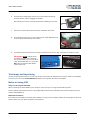
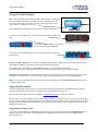
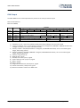
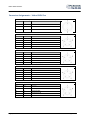
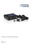
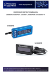
Video VBOX Hardware Manual Issue 10 13 August 2012 VIDEO VBOX MANUAL This page intentionally left blank Page | 2 13 August 2012 VIDEO VBOX MANUAL Introduction The Video VBOX is a multi-camera, solid state video recorder with GPS data-logging and graphical overlay. Included are three software packages: Circuit Tools Video VBOX Setup Performance tools - Lap analysis - Graphics and logging control - Detailed performance analysis Note: This manual is based on the latest firmware and software releases which are available for download from our website: www.videovbox.co.uk under ‘Support’ Page | 3 13 August 2012 VIDEO VBOX MANUAL Contents Introduction ........................................................................................................... 3 Quickstart Guide .................................................................................................... 5 Trackmaps and Lap-timing ..................................................................................... 6 Notes on using USB ................................................................................................ 6 SD cards ............................................................................................................................................ 7 USB memory sticks ........................................................................................................................... 7 Software Installation......................................................................................................................... 7 Video VBOX Registration .................................................................................................................. 7 Getting Started with your Video VBOX................................................................... 8 Logging Modes ....................................................................................................... 8 Log only when moving (default)................................................................................................................. 8 Manual logging ........................................................................................................................................... 8 CAN activated logging ................................................................................................................................ 8 LED functions – PRO 4 CAM ....................................................................................................................... 8 LED functions – Lite / Waterproof.............................................................................................................. 9 Tank circuit ............................................................................................................ 9 File formats ............................................................................................................ 9 Video format.......................................................................................................... 9 CAN Channels ........................................................................................................ 9 Using the OLED display ........................................................................................ 10 Auto Track Map elements ........................................................................................................................ 10 Multiple scene selection .......................................................................................................................... 10 Upgrading firmware ............................................................................................. 10 Upgrading multiple units ................................................................................................................ 10 CAN Output ..................................................................................................................................... 13 Connector Assignments – Video VBOX Pro .................................................................................... 14 Connector Assignments – Video VBOX Lite .................................................................................... 16 Connector Assignments – Video VBOX Waterproof....................................................................... 17 Contact Details..................................................................................................... 19 Page | 4 13 August 2012 VIDEO VBOX MANUAL Quickstart Guide As shipped, the Video VBOX can be used straight out of the box: 1. Mount the GPS antenna in the centre of the roof of the vehicle. Keep away from roof bars 2. Connect the antenna to the Video VBOX 3. Connect the power connector, it takes about 35s to start 4. Attach the camera to the windscreen using the forward facing camera mount, keep the camera level using the markings on the camera 5. Connect the camera to CAM1 Page | 5 13 August 2012 VIDEO VBOX MANUAL 6. The best way of alinging the camera is to use the optional Racelogic Preview monitor, which is plugged into AVOUT Alternatively you can use a Laptop connected via USB to get a live view 7. Take the car outside and wait for the Green GPS LED to illuminate 8. Insert the SD card and you are now ready to drive, Video VBOX will start to record Video automatically over 2.5kmh. 9. The REC LED will illuminate when recording, and when you come to a stop, it will flash as the file is closed. IMPORTANT - NEVER remove the SD card when this light is on or flashing – you will lose video. If you have come to a stop, but the REC LED is on, press the REC button to stop the video before removing the card. Trackmaps and Lap-timing To have lap-timing information or a circuit map shown on the video, the default internal ‘Scene’ needs to be modified. To do this, you can use the Video VBOX Setup software, see separate manual for more details. Notes on using USB Always use the Supplied USB Cable When connecting the Video VBOX to your computer, make sure you are using the USB cable supplied. Some ‘standard’ USB leads do not have a full length USB connector and will disable communication between your PC and the Video VBOX LITE. Mobile Phone Software Ensure that you shut down any mobile phone software running on your computer before connecting. We are aware of conflicts which can arise when using this kind of software. Page | 6 13 August 2012 SD cards When purchasing SD cards, always buy a quality brand such as SanDisk, Kingston or Lexar. Format : FAT32 USB memory sticks If data is to be logged to a USB memory device, the optional RLCAB073 cable is required. Software Installation To install the software insert the CD into the CD drive of your computer. NB: The software requires Microsoft .NET Framework 3.5 Service Pack 1 or higher to run. The installation CD contains the required .NET installation package. NB: In order to play back the AVI Video files, the XVid Codec pack must also be installed. The installation CD contains the required installation package. Video VBOX Registration So that Racelogic can continue to provide you with notification of the latest software releases, firmware upgrades and to offer technical support, please register your Video VBOX. Please register your unit here: www.videovbox.co.uk/register Alternatively, simply fill out the registration form supplied with the unit, and return to Racelogic. VIDEO VBOX MANUAL Getting Started with your Video VBOX Logging Modes The Blue LED will come on when the unit is recording video, this LED will flash when the unit is closing the file. DO NOT REMOVE the SD card if the Record LED is on or is flashing. The Video VBOX has three modes: Log only when moving (default) The unit automatically starts logging data when the vehicle speed goes above 2.5km/h, and stops when it goes below this value. This speed is configurable; see ‘Scene properties’ in Video VBOX Setup software. Pressing the REC button will stop the recording and close the file. Manual logging By pressing the REC button on the front of the unit, the user may override the Automatic logging function. The unit will then record until the card is full, the power is removed, or until the user presses the REC button once more. Note : to prevent potential loss of video, the unit will revert back to automatic logging after the car has been stationary for over 30 seconds and then starts to move again, or if the SD card is changed. CAN activated logging Logging can be controlled when a CAN channel is in (or out) of a certain value. More information on this can be found of page 22 of the Video VBOX Setup Software manual. LED functions – PRO 4 CAM LED COLOUR INDICATES PWR Red Power on CAMERAS Green A camera is connected CAN Red Correctly connected to a device and receiving CAN signals. Note, must be configured to receive in VVB setup software. SER Green Recognised serial information is being received. E.g. From a connected DriftBox USB Red USB logging media is connected GPS Red / Green i) Red indicates no satellite lock held ii) Green indicates SAT lock achieved MEMORY Red i) Amount of memory used in the attached logging media (incrementing sequence) ii) Status of scene upload or firmware upgrade (incrementing sequence) iii) Searching for media (in/out sequence) REC Blue Data being recorded to media. REC Button Blue i) Solid indicates that the unit is ready to log – media inserted ii) Flashing indicates uploading of either a scene or firmware is taking place Page | 8 13 August 2012 VIDEO VBOX MANUAL LED functions – Lite / Waterproof LED COLOUR INDICATES PWR Green Power on STATUS Green i) Solid indicates that the unit is ready to log – media inserted ii) Flashing indicates uploading of either a scene or firmware is taking place GPS Green i) Flashing indicates searching for satellites after GPS cold start ii) Solid indicates SAT lock achieved RECORD Green Data being recorded to logging media Tank circuit Every Video VBOX contains a small internal battery to prevent loss of video should the power supply be interrupted for any reason. This battery is continually recharged during normal operation. When the power is interrupted, the unit will start to beep, and the symbol on the right will appear on the video. If after 5 seconds the power is still not present, the unit will close the Video file and shut the box down safely. File formats The Video VBOX will log either to an SD card or a USB drive (requiring cable RLCAB073). Two files are logged, an ‘.avi’ Video File (compatible with the Xvid codec which is installed with the software package), and a synchronised ‘.vbo’ data file which contains all of the GPS (and CAN, if applicable) data in ASCII format, recorded 10 times a second (or 20 if you are using a VVB Pro 20Hz unit). The files are stored under the ‘media’ folder. The maximum size of files for SD cards in FAT32 format is 2Gbytes. If you record for more than 50 minutes, a new ‘.avi’ file is created. Therefore a single ‘.vbo’ file can be associated with multiple ‘.avi’ files. Video format Standard definition uses 720x576 pixels at 25 frames per second for PAL and 720x480 pixels at 30 frames per second for NTSC. All video is interlaced, this is the DVD standard as it was originally designed for a scanning line TV set. When replayed on a Computer screen instead of a TV, you may see ‘motion artefacts’ which are the result of the interlaced format. When you upload your content to YouTube, or display on a normal television, the interlacing is removed. Windows Media Player does not render the video as well as other media players, so for better quality, Racelogic recommend the free, but excellent, VLC player (http://www.videolan.org/vlc/) which has a de-interlacing filter (Video - De-Interlace - Blend). For a detailed explanation of interlacing also see here: www.100fps.com CAN Channels All units can log parameters from the CAN bus, basic units can log a single channel, ‘VCI’ enabled units can log up to 32 channels. Page | 9 13 August 2012 VIDEO VBOX MANUAL Using the OLED display When setting up the DSP04 OLED display with a Video VBOX, it is important to connect to the correct port of the OLED display. The OLED display only has a serial connection on the lower connector, with the buttons on the right hand side - as shown in this picture. The configuration is indicated on a label on the rear of the OLED display. To connect to a Video VBOX Lite, you should connect the cable into the ‘AUX’ port. To connect to a Video VBOX Pro, you should connect the cable into the ‘SER’ port. To connect to a Video VBOX Waterproof, you should connect the cable into the ‘SER’ port. Auto Track Map elements – If an Auto Track Map element has been added to the scene currently loaded in the Video VBOX, the OLED can be used to specify which track layout to display. Once a GPS location is detected, the VideoVBOX will display a circuit layout for that location – e.g. If Silverstone location detected, Silverstone GP, National and International layouts will be displayed. Multiple scene selection – The Video VBOX can store up to eight scenes. They are loaded by placing them in the root folder of an SD card and inserting them into a VVB. The user can select the scene using an OLED display. Note, if the user tries to load more than eight scenes, the Video VBOX will reject all the scene files and write an error message to the SD card. Upgrading firmware Occasionally Racelogic will release new versions of firmware (internal code) for the Video VBOX product, often to introduce new features. New firmware is loaded into the Video VBOX using an SD card. Download the latest ‘.vidup’ file from our website: www.videovbox.co.uk (Found under ‘Support’) Copy this file onto an SD card (not into the ‘media’ folder), and insert into a powered unit. The memory LEDs will light up in turn as the update progresses (2CAM/ Pro) or the Status LED will flash (Lite). After a period of up to two minutes, the unit will beep twice and resume operation. The unit should then be power cycled. The upgrade file will have been deleted from the SD card. Upgrading multiple units To prevent the Video VBOX from deleting the firmware file, create an empty text file called ‘no-delete-vidup.txt’ on the SD card in the same directory as the upgrade file, the upgrade file will then remain on the card following a successful upgrade. Page | 10 13 August 2012 VIDEO VBOX MANUAL Troubleshooting Guide Trouble Locking onto Satellites Place the antenna where it has an unobstructed view of the sky. (See ‘GPS Antenna Placement’ below) Perform a GPS Coldstart by pressing and holding the REC button for 5 seconds until the unit beeps 5 times. Then leave the unit powered up in an open static position for at least 15 minutes Check the antenna connection is very clean; small amounts of dirt in the socket can cause a significant reduction in signal strength Try another antenna GPS Antenna Placement For optimum GPS signal reception, make sure that the antenna is fitted to the highest point of the vehicle away from any obstructions that may block satellite reception. The GPS antenna works best with a metal ground plane underneath, silver foil, or a metal plate beneath the antenna can improve reception significantly if you don’t have a large metal roof. We do a larger antenna with a very good internal ground plane which can operate perfectly without the need for mounting on a metal surface (part number RLVBACS065) which also gives superior position accuracy. No Communication with PC Check power In the case of the Video VBOX Lite, only use the USB cable (CAB066-2) supplied with the unit, as other cables such as those supplied with card readers may not have a long enough plug to fit into the recessed socket on the front of the box Try disconnecting then reconnecting the USB cable with the Video VBOX powered Check that no other programs are using the same COM port Shut down any Mobile Phone software running on your PC Disconnect the power to the Video VBOX then reconnect it COM Port Unavailable Disconnect the Video VBOX, restart the computer then reconnect the Video VBOX Another software package installed on your computer may have reserved the COM port Video Data is Corrupt The storage media may have been removed from the unit before the file is closed. It is possible to recover corrupted video files using either DivFix (http://divfix.maxeline.com) or VirtualDubMod (http://virtualdubmod.sourceforge.net) If unsure how to recover corrupted video files contact [email protected] You can fix most problems with lost files by right clicking on the card in Windows explorer and selecting ‘Propeties’ – ‘Tools’ – ‘Error checking’ tick both boxes, and click ‘Check now’ Always wait for the logging light to stop flashing before removing the SD card or USB device. You can force the box to close the file using the REC button. Cannot Open Video File The XVid Codec may need to be re-installed (http://www.xvid.org) Video VBOX LITE Beeps continuously The SD card may be full The scene may be corrupt, try re-uploading the scene Try to re-flash the firmware Page | 11 13 August 2012 VIDEO VBOX MANUAL Only Audio is present during playback. The XVid Codec may need to be re-installed (http://www.xvid.org) No speed shown on video Check GPS reception Video Overlay is missing some or all Elements Scene should not be larger than 12 Mb due to space limitation in the unit Scene does not upload to the Video VBox Try a re-installation of the firmware on the Video VBox and try to upload the scene again Video VBOX not responding - GPS Coldstart The GPS engine has locked up. Perform a GPS Engine Coldstart – hold REC button for 5 seconds Page | 12 13 August 2012 VIDEO VBOX MANUAL CAN Output The Video VBOX Pro has a CAN output which is present on the 5-way connector output. Data format: Motorola Baud rate: 500Kb/s ID* Data Bytes Update Rate 1 2 3 4 5 6 7 8 0x301 100ms 0x302 100ms (1) Sats in (2) Time since midnight UTC view (4) Position – Longitude MMMM.MMMMM (3) Position – Latitude MMMM.MMMMM 0x303 100ms (7) Altitude. WGS 84. (Metres) 0x304 100ms Unused (11) Longitudinal Accel. (G) (12) Lateral Accel. (G) 0x305 100ms (13) Distance travelled since VBOX reset (Metres) Unused Unused (5) Velocity. (Knots) (8) Vertical velocity. (M/S) Unused (6) Heading (Degrees) (9) Status (10) Status 1) If Satellites in view < 3 then only Identifier 0x301 transmitted and bytes 2 to 8 are set to 0x00. 2) Time since midnight. This is a count of 10ms intervals since midnight UTC. (5383690 = 53836.90 seconds since midnight or 14 hours, 57 minutes and 16.90 seconds). 3) Position, Latitude * 100,000 (311924579 = 51 Degrees, 59.24579 Minutes North). This is a true 32bit signed integer, North being positive. 4) Position, Longitude * 100,000 (11882246 = 0 Degrees, 58.82246 Minutes West). This is a true 32bit signed integer, West being positive. 5) Velocity, 0.01 knots per bit. o 6) Heading, 0.01 per bit. 7) Altitude, 0.01 meters per bit, signed. 8) Vertical Velocity, 0.01 m/s per bit, signed. 9) Status, unused. 10) Status, unused. 11) Longitudinal Acceleration, 0.01G per bit, signed. 12) Lateral Acceleration, 0.01G per bit, signed. 13) Distance travelled in meters since VBOX reset. Page | 13 13 August 2012 VIDEO VBOX MANUAL Connector Assignments – Video VBOX Pro Connector 1 – Power (Dedicated 9V to 15V DC Power Connector) Pin I/O Function Page | 14 1 I Power + 2 I Ground Chassis I Ground Connector 2 – Camera 1 Pin I/O 1 O 2 I 3 O 4 O 5 I Function Audio Ground Video Input Camera Power Camera Ground Audio Input (Left) Connector 3 – Camera 2 Pin I/O 1 O 2 I 3 O 4 O 5 I Function Audio Ground Video Input Camera Power Camera Ground Audio Input (Right) Connector 4 – Camera 3 Pin I/O 1 2 I 3 O 4 O 5 - Function Video Input Camera Power Camera Ground - Connector 5 – Camera 4 Pin I/O 1 2 I 3 O 4 O 5 - Function Video Input Camera Power Camera Ground - 13 August 2012 VIDEO VBOX MANUAL Connector 6 – CAN Pin I/O 1 2 3 I/O 4 I/O 5 O Function CAN High CAN Low Power Connector 7 – SER Pin I/O 1 O 2 I 3 I/O 4 I/O 5 O Function Tx-RS232 Rx-RS232 CAN High CAN Low Power Connector 8 – USB Pin I/O 1 I 2 I/O 3 O 4 I/O 5 I/O Function USB - ID DP Ground USB 5V DM Connector 9 – AUX Out Pin I/O 1 O 2 O 3 I 4 O 5 O 6 O Function Ground Video Output Digital Input Digital Output Audio Output Power (1A Max) Connector 10 – MIC Pin I/O 1 O 2 3 I 4 I 5 O Function Ground Audio –right channel Audio –left channel Power Connector 11 – GPS (GPS Antenna) Pin I/O Function Page | 15 1 I Signal Chassis I Ground 13 August 2012 VIDEO VBOX MANUAL Connector Assignments – Video VBOX Lite Connector 1 – PWR Pin I/O 1 I 2 I Function Power + (9 to 15V) Ground (0V) Connector 2 – CAM1 Pin I/O 5 I/O 7 I 3 O Function Ground Video input Camera Power (8 – 18V) Connector 3 – CAM2 Pin I/O 5 I/O 7 I 3 O Function Ground Video input Camera Power (8 – 18V) Connector 4 – CAN Pin I/O 1 O 2 I/O 3 I/O 5 I/O 6 I 8 O Function Digital Output CAN High CAN Low Ground Digital Input Power Connector 5 – AUX Pin I/O 1 I 3 O 5 I/O 6 O 8 I Function RS232 TxD RS232 RxD Ground Video Out Power +12V (1A Max) Connector 7 – GPS (GPS Antenna) Pin I/O Function 1 I Signal Chassis I Ground Connector 6 – USB Pin I/O 1 I Page | 16 Function USB – 5V 13 August 2012 VIDEO VBOX MANUAL Connector Assignments – Video VBOX Waterproof Connector 1 – Power (Dedicated 9V to 15V DC Power Connector) Pin I/O Function 1 I Power 2 I Ground 3 - N/C Connector 2 – Camera 1 Pin I/O Function 1 O Power 2 O Ground 3 I Video Input Connector 3 – Camera 2 Pin I/O Function 1 O Power Page | 17 2 O Ground 3 I Video Input Connector 4 – MIC Pin I/O 1 I 2 3 O 4 O 6 I 6 - Function Mic In Right Reserved AV Ground Power Mic In Left Reserved Connector 5 – USB Pin I/O 1 I/O 2 I/O 3 I/O 4 I/O 5 I/O 6 I Function Data Positive Data Minus VBUS Shield Ground ID 13 August 2012 VIDEO VBOX MANUAL Page | 18 Connector 6 – CAN Pin I/O 1 2 3 4 5 6 I/O 7 I/O 8 9 10 11 O 12 O Function N/C N/C N/C N/C N/C CAN High CAN Low N/C Reserved Reserved Power Ground Connector 7 – SER Pin I/O 1 2 3 4 5 6 I/O 7 I/O 8 9 I 10 O 11 O 12 O Function N/C N/C N/C N/C N/C CAN High CAN Low N/C RxD TxD Power Ground Connector 8 – AUX Pin I/O 1 O 2 O 3 O 4 O 5 I 6 I/O 7 I/O 8 9 10 11 O 12 O Function Video Out Audio Out AV Ground Digital Out Digital In CAN High CAN Low N/C N/C N/C Power (1A Max) Ground 13 August 2012 VIDEO VBOX MANUAL Connector 9 – GPS (GPS Antenna) Pin I/O Function 1 I Signal Chassis I Ground Contact Details Racelogic Unit 10 Swan Business Centre Osier Way Buckingham Bucks MK18 1TB United Kingdom Email: Web: [email protected] www.racelogic.co.uk Page | 19 13 August 2012