1
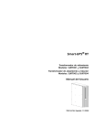
APC Step-Down Transformer
Models: AP9621, SURT005,
SURT006, SUTF3, SYTF2,
SYTF2J, SYTF3 and SYTF3J
User’s Manual
English
990-7820D, July 2003
TABLE OF CONTENTS
APC Contact Numbers and Support
Visit the APC Web site for contact numbers and support at http://www.apc.com/support.
Chapter 1: Safety and General Information................................................................. 1
Save These Instructions ............................................................................................................................................ 1
Conventions Used in this Manual .............................................................................................................................. 1
Handling Safety ......................................................................................................................................................... 1
De-energizing Safety ................................................................................................................................................. 2
Electrical Safety......................................................................................................................................................... 2
Regulatory Agency Approvals ................................................................................................................................... 2
Life Support Policy..................................................................................................................................................... 3
Limited Warranty ....................................................................................................................................................... 3
Copyright and Trademark Information ....................................................................................................................... 3
Chapter 2: Basics .......................................................................................................... 5
About Your Step-Down Transformer ......................................................................................................................... 5
Product Overview ...................................................................................................................................................... 6
Front View Component Identification..................................................................................................................... 7
Rear View Component Identification ..................................................................................................................... 7
Chapter 3: Installation ................................................................................................... 7
Unpacking ................................................................................................................................................................. 8
Inspection .............................................................................................................................................................. 8
Contents ................................................................................................................................................................ 8
Installing the Step-Down Transformer ....................................................................................................................... 8
Installing in a Four-Post Rack................................................................................................................................ 8
Wiring the Step-Down Transformer ....................................................................................................................... 9
Connecting Load Equipment ............................................................................................................................... 10
Turning On the Step-Down Transformer ............................................................................................................. 10
Using the Step-Down Transformer ...................................................................................................................... 11
Chapter 4: Specifications............................................................................................ 11
Product Specifications ............................................................................................................................................. 12
TABLE OF CONTENTS
CHAPTER 1: SAFETY AND GENERAL INFORMATION
Save These Instructions
This Safety section contains important instructions that must be followed during installation and maintenance
of APC equipment.
Conventions Used in this Manual
The following symbols are used throughout this manual. Carefully read all information boxes and abide by
the instructions.
The WARNING sign denotes a serious hazard. It calls attention to a procedure, practice,
condition, or the like, which, if not correctly performed or adhered to, could result in injury
to personnel.
The CAUTION sign denotes a hazard. It calls attention to an operating procedure, practice, or
the like, which, if not correctly performed or adhered to, could result in damage to or destruction
of all or part of the product.
The NOTE sign denotes important information. It calls attention to a procedure, practice,
condition, or the like, which is essential to highlight.
Handling Safety
Be careful. Do not lift heavy loads without assistance.
32 – 55 kg (70 – 120 lb)
This equipment is intended for installation in a temperature-controlled indoor area free of
conductive contaminants. Refer to Specifications at the APC web site (www.apc.com/support/)
for the actual temperature range.
1
CHAPTER 1: SAFETY AND GENERAL INFORMATION
De-energizing Safety
To de-energize this equipment toggle the rear input circuit breaker to the OFF position, and then
disconnect the equipment from the AC power outlet.
Electrical Safety
• The protective earth conductor carries the leakage current from the load devices (computer
equipment). Therefore, the size of the conductor must be at least as large as the wire required
by IEC 950. An insulated grounding conductor that is identical in size, insulation material, and
thickness to the grounded and ungrounded branch-circuit supply conductors, except that it is
green with or without a yellow stripe is to be installed as part of the branch.
• The grounding conductor described above is to be grounded to earth at the service
equipment, or if supplied by a separately derived system, at the supply transformer or motorgenerator set.
• The attachment-plug receptacles near the unit or subsystem are all to be of a grounding type,
and the grounding conductors serving these receptacles are to be connected to earth ground
at the service equipment.
• To reduce the risk of fire, connect only to a circuit provided with 30-amp maximum branch
circuit overcurrent protection in accordance with the National Electrical Code, ANSI/NFPA.
Regulatory Agency Approvals
Regulatory Agency Symbols
LISTED 42C2
E95463
LR63938
2
CHAPTER 1: SAFETY AND GENERAL INFORMATION
Life Support Policy
As a general policy, American Power Conversion (APC) does not recommend the use of any of its products in
life support applications where failure or malfunction of the APC product can be reasonably expected to cause
failure of the life support device or to significantly affect its safety or effectiveness. APC does not recommend the
use of any of its products in direct patient care. APC will not knowingly sell its products for use in such
applications unless it receives in writing assurances satisfactory to APC that (a) the risks of injury or damage
have been minimized, (b) the customer assumes all such risks, and (c) the liability of American Power
Conversion is adequately protected under the circumstances.
Examples of devices considered to be life support devices are neonatal oxygen analyzers, nerve stimulators
(whether used for anesthesia, pain relief, or other purposes), autotransfusion devices, blood pumps,
defibrillators, arrhythmia detectors and alarms, pacemakers, hemodialysis systems, peritoneal dialysis systems,
neonatal ventilator incubators, ventilators for both adults and infants, anesthesia ventilators, infusion pumps, and
any other device designated as “critical” by the U.S.F.D.A.
Hospital grade wiring devices and reduced leakage currents that meet medical safety standards may be ordered
as options on many APC UPS systems. APC does not claim that units with these modifications are certified or
listed as such by APC or any other organization, therefore these units do not meet the requirements for use in
direct patient care.
Limited Warranty
American Power Conversion (APC) warrants its products to be free from defects in materials and workmanship
for a period of two years from the date of purchase, except in India where the period is one year for battery
module(s). Its obligation under this warranty is limited to repairing or replacing, at its own sole option, any such
defective products. To obtain service under warranty you must obtain a returned material authorization (RMA)
number from customer support. Products must be returned with transportation charges prepaid and must be
accompanied by a brief description of the problem encountered and proof of date and place of purchase. This
warranty does not apply to equipment that has been damaged by accident, negligence, or misapplication or has
been altered or modified in any way. This warranty applies only to the original purchaser who must have properly
registered the product within 10 days of purchase.
EXCEPT AS PROVIDED HEREIN, AMERICAN POWER CONVERSION MAKES NO WARRANTIES,
EXPRESSED OR IMPLIED, INCLUDING WARRANTIES OF MERCHANTABILITY AND FITNESS FOR A
PARTICULAR PURPOSE. Some states do not permit limitation or exclusion of implied warranties; therefore, the
aforesaid limitation(s) or exclusion(s) may not apply to the purchaser.
EXCEPT AS PROVIDED ABOVE, IN NO EVENT WILL APC BE LIABLE FOR DIRECT, INDIRECT, SPECIAL,
INCIDENTAL, OR CONSEQUENTIAL DAMAGES ARISING OUT OF THE USE OF THIS PRODUCT, EVEN IF
ADVISED OF THE POSSIBILITY OF SUCH DAMAGE. Specifically, APC is not liable for any costs, such as lost
profits or revenue, loss of equipment, loss of use of equipment, loss of software, loss of data, costs of
substitutes, claims by third parties, or otherwise. This warranty gives you specific legal rights and you may have
other rights that vary from state to state.
Copyright and Trademark Information
Entire contents copyright © 2003 by American Power Conversion Corporation. All rights reserved. Reproduction
in whole or in part without permission is prohibited.
®
®
®
®
®
®
®
APC , Symmetra , Smart-UPS , Smart-UPS RT , NetShelter , InfraStruXure and PowerChute are
registered trademarks of American Power Conversion Corporation. All other trademarks are the property of their
respective owners
3
CHAPTER 1: SAFETY AND GENERAL INFORMATION
4
CHAPTER 3: INSTALLATION
About Your Step-Down Transformer
This Step-Down Transformer is designed for use with a
UPS that provides a higher output voltage (200 or 208
VAC).
It converts the output to a lower voltage (100 or 120
VAC); a common voltage level used by many computers
and accessories.
Figure 1:
Table 1:
System Configurations and Model Numbers
Complete
System–
End Item
SKU
North
America
and
208V
(Ø- Ø -G)
The Step-Down Transformer may also be used as a
stand-alone device.
Step-Down Transformer
Available
Power VA
AP9621,
SYTF2,
SURT005
4500*
SYTF3,
SUTF3
4500
Nominal
Input
Voltage
VAC
208
Nominal
Output
Voltage VAC
120
Frequency
Hz
60
5000**
Power
Distribution
Input: 3-foot cord with L630P or hardwired.
*** Output: (2) 15-amp
circuits with (4) 5-20R
T-slots and (2) 15-amp
circuits with (2) 5-20R
T-slots, or hardwired.
208
120
60
Input: 2-foot cord
with L6-30P.
*** Output: (4) 20-amp
circuits with (4) L5-20R.
Japan
and
200 V
(Ø- Ø -G)
SYTF2J,
SURT006
3500
200
100
50 or 60
Input: 3-foot cord with
L6-30P.
***Output: (2) 15-amp
circuits with (4) 5-20R
T-slots and (2) 15-amp
circuits with (2) 5-20R
T-slots.
SYTF3J
3500
200
100
50 or 60
Input: 2-foot cord
with L6-30P.
***Output: (4) 20-amp
circuits with (4) L5-20R.
* Power cord connected units have an available power of 4500 VA with a L6-30 plug.
** Units with an available power of 5000 VA must be hardwired due to input current.
*** Ensure that the pin number for T-slot receptacles is correct.
5
CHAPTER 3: INSTALLATION
Product Overview
6
CHAPTER 3: INSTALLATION
Front View Component Identification
Rail Cleats : Two cleats (one on each side) of
the Step-Down Transformer engage with the rack
mounting rails to secure in the equipment rack.
Mounting Flanges : Two mounting flanges
(Figure 2 and 4) secure the Step-Down Transformer
in the rack.
Figure 2:
Front Bezel : A bezel covers the front of the StepDown Transformer. The bezel is removed during the
installation for the SUTF3, SYTF2, SYTF2J, SYTF3
and SYTF3J models.
AP9621
Fans : Two fans on the front of the Step-Down
transformer circulate airflow and cool the unit. The
redundant fan will not operate unless the internal
temperature of the unit becomes 100 °F or failure of
the main cooling fan.
Figure 3: SUTF3 / SYTF2 / SYTF2J /
SYTF3 / SYTF3J
Figure 7:
SUTF3 / SYTF2 / SYTF2J / SYTF3 /
SYTF3J / SURT005 / SURT006
Figure 4: SURT005/ SURT006
Rear View Component Identification
Input Wiring : Provides access to wiring terminal
blocks for hard wiring the input (see Figure 6).
Provided with an input cord for use in many
applications (see Figure 7).
Input Circuit Breaker : The input circuit breaker
protects the product and load equipment from
extreme overloads.
Figure 5:
AP9621 / SYTF2 / SYTF2J /
SURT005 / SURT006
Figure 6:
SUTF3 / SYTF3 / SYTF3J
Power Distribution Unit (PDU) : Power
distribution receptacles for connecting load
equipment.
7
CHAPTER 3: INSTALLATION
Unpacking
The Step-Down Transformer is packaged in a robust shipping carton. Carefully remove the package contents. The
packaging is recyclable; save it for reuse or dispose of it properly.
Inspection
Inspect the equipment upon receipt. APC has designed robust packaging for your product. However, accidents
and damage may occur during shipment. Notify the carrier and dealer if there is damage or missing equipment.
Contents
Check the packaging contents. The shipping package contains the Step-Down Transformer, mounting rails, and
mounting hardware. Your package may contain a Bezel Kit. If the bezel is not already installed, snap it on to the
UPS as instructed below.
Installing the Step-Down Transformer
This section provides information on the steps required to install and connect the Step-Down Transformer.
Installing in a Four-Post Rack
Follow the instructions contained in the Addendum SU Rack-Mount Rails 2U-5U sheet (990-7034G) to mount
the rails in your NetShelter or 19 in (46.5 cm) rack.
*It is recommended that the Step-Down Transformer is installed directly above the UPS in the rack.
1.
Install the mounting rails using the instructions contained
in the Rail Kit.
2.
Slide the Step-Down Transformer frame into the rack.
The Step-Down Transformer is heavy.
Three people must support the unit.
Figure 8:
AP9621 / SURT005 / SURT006
3.
To secure the Step-Down Transformer frame in the rack,
screw the four decorative screws through the holes in the
ears of the UPS and into the screw clips.
4.
If the bezel has not already been attached, align the tabs
on the sides of the bezel with the slots on the front of the
Step-Down Transformer and gently snap it into place.
Install the bezel with the rear fins
facing down.
Figure 9: SUTF3 / SYTF2 / SYTF2J /
SYTF3 / SYTF3J
8
CHAPTER 3: INSTALLATION
Wiring the Step-Down Transformer
1.
For cord connected installations, plug the input power
cord into the outlet .
2.
For hardwired installations:
• Verify that all branch circuit (mains)
are de-energized and locked out
before installing cables or making
connections.
• Wiring by a licensed electrician is
required.
• Check national and local codes
before wiring.
• Use 10-gauge (6 mm2) wire.
3.
Make sure the input circuit breaker is OFF.
a.
Remove the input-wiring access panel .
b.
Disconnect the power cord from terminal block .
c.
Connect the new wires to the terminal block.
d.
Each terminal is labeled. The Step-Down
Transformer requires a 208 VAC single-phase input
from a power source with a minimum branch breaker
rating of 30-amps.
Inspect the connections.
e.
f.
9
Attach the new access panel provided in the
literature kit.
CHAPTER 3: INSTALLATION
Connecting Load Equipment
Plug all load equipment into PDU receptacles.
• For AP9621, SYTF2, SYTF2J, SURT005, and SURT006
models, the receptacles are divided into 4 groups; each
group is protected by a 15-amp circuit breaker. A colored
label identifies each circuit and its circuit breaker.
• For SUTF3, SYTF3 and SYTF3J models, the output is
divided into 4 groups. Each group is protected by a 20-amp
circuit breaker that contains one (1) receptacle.
• When connecting the equipment, distribute the loads
evenly on the four output circuits.
Turning On the Step-Down Transformer
1.
Turn on the Step-Down Transformer by switching the rear
panel input circuit breaker to the ON position.
For AP9621, SYTF2, SYTF2J, SURT005, and SURT006
models, a colored label identifies each circuit and its
circuit breaker.
2.
Turn on all connected equipment.
Depending on your required output power,
one of the fans may not be turning
because the internal temperature of the
Step-Down Transformer is less than
100°F. If 100°F is reached, the redundant
fan will turn on.
10
CHAPTER 3: INSTALLATION
Using the Step-Down Transformer
• Connect the Step-Down Transformer to a UPS for continuous power during a utility
power failure.
• The transformer has an efficiency of 90%. This requires 5500 VA for a 5000 VA load, 5000 VA
for a 4500 VA load, and 3900 VA for a 3500 VA load. Be careful not to overload your branch
circuit or UPS.
• For the AP9621, SYTF2, and SURT005 models to output the full 5000 VA, the input must be
hardwired to a 5500 VA source.
• Operating the Step-Down Transformer below its specified input voltage range may cause it
to overload and shut down to prevent it from over-heating. When connecting directly to a
branch circuit, ensure that the line voltage is within specification. When connecting to a UPS,
ensure that the line voltage into the UPS is within specification before transferring to bypass.
• Operating the Step-Down Transformer above its input voltage range may cause equipment
damage.
11
CHAPTER 4: SPECIFICATIONS
Product Specifications
Electrical Specifications
AP9621 / SUTF3 / SYTF2 /
SYTF3 / SURT005
SYTF2J / SYTF3J / SURT006
Nominal Input Voltage (VAC)
208
200
Input Voltage Range (VAC)
185 to 230*
180 to 220
Line cord Installation (L6-30)
24
22
Hardwire Installation
26**
Maximum Input Current (amps)
Line Frequency (Hz)
60
50 or 60
Efficiency
90 to 95%
Nominal Output Voltage (VAC)
120
100
Line cord Installation (L6-30)
4500*
3500
Hardwire Installation
5000*
3500
Maximum Output Power (VA)
* For continuous operation below Vin = 205 VAC, the output load must be reduced to limit the maximum input
current to the amount specified in the table above. Continuous operation above the maximum specified input
current may cause the unit to overheat and shutdown. Please contact APC for additional information.
** Not available on SUTF3 and SYTF3 models.
12
CHAPTER 4: SPECIFICATIONS
Other Specifications
Dimensions (H x W x D)
(Overall)
3.5 in x 19 in x 26 in (with bezel)
(8.9 cm x 48.3 cm x 66 cm)
Weight
Net
95 lbs (43kg)
Shipping
110 lbs (50 kg)
Temperature
Operating
0 to 40°C
Storage
–25 to 65° C
Humidity, relative
Operating and storage
5 to 95%
Elevation
Operating
0 to +3,000 m (0 to +10,000 ft)
Storage
0 to +15,000 m (0 to +50,000 ft)
Agency Approvals
UL 1778 (AP9621, SUTF3, SYTF2, SYTF2J, SYTF3, SYTF3J, SURT005,
and SURT006 models)
CSA 66 (AP9621, SUTF3, SYTF2, and SYTF3 models)
13