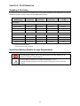
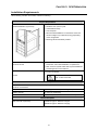
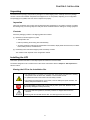
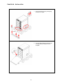
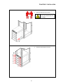
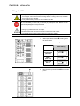
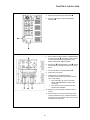
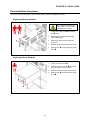
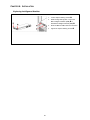
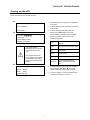
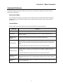
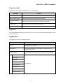
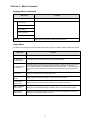
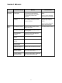
1
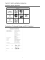
APC Symmetra RM
4–12 kVA UPS
Installation Manual
English
990-7810B, August 2002
TABLE OF CONTENTS
Chapter 1: Safety and General Information........................................................ 1
Save These Instructions ----------------------------------------------------------------------------------------------------------------------1
Conventions Used in this Manual-----------------------------------------------------------------------------------------------------------1
General Equipment Safety -------------------------------------------------------------------------------------------------------------------1
Handling Safety ---------------------------------------------------------------------------------------------------------------------------------1
Deenergizing Safety ---------------------------------------------------------------------------------------------------------------------------2
Electrical Safety ---------------------------------------------------------------------------------------------------------------------------------2
Battery Safety------------------------------------------------------------------------------------------------------------------------------------2
Battery Replacements Kits and Battery Recycling -------------------------------------------------------------------------------------3
PowerStruXure Type A Systems -----------------------------------------------------------------------------------------------------------3
Radio Frequency Interference ---------------------------------------------------------------------------------------------------------------3
North America and 208 V Countries----------------------------------------------------------------------------------------------------3
Europe and 230 V Countries -------------------------------------------------------------------------------------------------------------3
Japan and 200 V Countries---------------------------------------------------------------------------------------------------------------3
Regulatory Agency Approvals ---------------------------------------------------------------------------------------------------------------4
Declaration of Conformity (Europe and 230 V Countries) ----------------------------------------------------------------------------4
Life Support Policy -----------------------------------------------------------------------------------------------------------------------------5
Limited Warranty--------------------------------------------------------------------------------------------------------------------------------5
Copyright and Trademark Information-----------------------------------------------------------------------------------------------------5
APC Contact Numbers and Support -------------------------------------------------------------------------------------------------------5
Chapter 2: Basics .............................................................................................. 7
About Your UPS --------------------------------------------------------------------------------------------------------------------------------7
Product Overview-------------------------------------------------------------------------------------------------------------------------------9
Front View Component Identification---------------------------------------------------------------------------------------------------9
Rear View Component Identification ------------------------------------------------------------------------------------------------- 10
System Block Diagram ------------------------------------------------------------------------------------------------------------------- 11
Chapter 3: Site Preparation ............................................................................. 13
Reminder Checklist -------------------------------------------------------------------------------------------------------------------------- 13
Purchase of System ---------------------------------------------------------------------------------------------------------------------- 13
Site Preparation---------------------------------------------------------------------------------------------------------------------------- 13
Electrical Preparation--------------------------------------------------------------------------------------------------------------------- 13
Shipping & Receiving ------------------------------------------------------------------------------------------------------------------------ 14
Short-Term Battery Module Storage Requirements --------------------------------------------------------------------------------- 14
Installation Requirements------------------------------------------------------------------------------------------------------------------- 15
Electrical Requirements --------------------------------------------------------------------------------------------------------------------- 16
TABLE OF CONTENTS
Chapter 4: Installation..................................................................................... 17
Unpacking -------------------------------------------------------------------------------------------------------------------------------------- 17
Inspection ----------------------------------------------------------------------------------------------------------------------------------- 17
Contents ------------------------------------------------------------------------------------------------------------------------------------- 17
Installing the UPS----------------------------------------------------------------------------------------------------------------------------- 17
Moving the UPS to the Installation Site ---------------------------------------------------------------------------------------------- 17
Installing in a Four Post Rack ---------------------------------------------------------------------------------------------------------- 19
Wiring the UPS----------------------------------------------------------------------------------------------------------------------------- 22
Completing the Installation-------------------------------------------------------------------------------------------------------------- 25
Connecting Load Equipment to the UPS -------------------------------------------------------------------------------------------- 27
Final Installation Checklist -------------------------------------------------------------------------------------------------------------- 28
Post Installation Procedures --------------------------------------------------------------------------------------------------------------- 29
Replacing Battery Modules ------------------------------------------------------------------------------------------------------------- 29
Replacing Power Modules -------------------------------------------------------------------------------------------------------------- 29
Replacing Intelligence Modules-------------------------------------------------------------------------------------------------------- 30
Chapter 5: Specifications ................................................................................. 31
Technical Reference ------------------------------------------------------------------------------------------------------------------------- 31
CHAPTER 1: SAFETY AND GENERAL INFORMATION
Save These Instructions
This Safety section contains important instructions that must be followed during installation and maintenance of APC
equipment.
Conventions Used in this Manual
The following symbols are used throughout this manual. Carefully read all information boxes and abide by the
instructions.
The WARNING sign denotes a serious hazard. It calls attention to a procedure, practice,
condition, or the like, which, if not correctly performed or adhered to, could result in injury
to personnel.
The CAUTION sign denotes a hazard. It calls attention to an operating procedure, practice, or
the like, which, if not correctly performed or adhered to, could result in damage to or destruction
of all or part of the product.
The NOTE sign denotes important information. It calls attention to a procedure, practice,
condition, or the like, which is essential to highlight.
General Equipment Safety
• Connection to the branch circuit (mains) must be performed by a licensed electrician.
• Installation and removal of the power, battery, intelligence modules, and interface accessories
must be performed by service personnel.
Operation of the equipment can be performed by any individual with no previous technical
experience.
Handling Safety
Be careful. Do not lift heavy loads without assistance.
<18 kg (<40 lb)
32 – 55 kg (70 – 120 lb)
18 – 32 kg (40 – 70 lb)
>55 kg (>120 lb)
This equipment is intended for installation in a temperature-controlled indoor area free of
conductive contaminants. Refer to Specifications at the APC web site for the actual temperature
range.
1
CHAPTER 1: SAFETY AND GENERAL INFORMATION
Deenergizing Safety
The UPS contains internal batteries and may present a shock hazard even when disconnected
from the branch circuit (mains). Before installing or servicing the equipment, ensure that the
system enable switch and input circuit breaker are set to stand-by (OFF), that internal battery
modules are removed, that external extended run batteries are disconnected and the branch
circuit (mains) is disconnected.
Electrical Safety
• The protective earth conductor for the UPS carries the leakage current from the load devices
(computer equipment). Therefore, the size of the conductor must be at least as large as the
wire required by IEC 950. An insulated grounding conductor that is identical in size, insulation
material, and thickness to the grounded and ungrounded branch-circuit supply conductors,
except that it is green with or without a yellow stripe is to be installed as part of the branch
circuit that supplies the UPS.
• The grounding conductor described above is to be grounded to earth at the service
equipment, or if supplied by a separately derived system, at the supply transformer or motorgenerator set.
• The attachment-plug receptacles near the unit or subsystem are all to be of a grounding type,
and the grounding conductors serving these receptacles are to be connected to earth ground
at the service equipment.
Battery Safety
• Each battery module is a 120 V, 7.2 Ah battery pack. There is a risk of energy hazard. Before
installing or replacing battery nodules, remove jewelry such as wristwatches and rings. High
short -circuit current through conductive materials could cause severe burns.
• Do not dispose of batteries in a fire. The batteries may explode.
• Do not open or mutilate batteries. Released electrolyte is harmful to the skin and eyes, and
may be toxic.
Do not install the battery modules in the frame until you are ready to power up the UPS. Failure
to do so can result in a deep discharge of the batteries, which may cause permanent damage.
• Batteries are recyclable. Used batteries can be sent to APC for recycling or delivered to a
recycling facility.
• Store the battery module(s) at a cool ambient temperature of < 25 °C.
• Only use APC batteries when adding or replacing battery modules in the UPS.
2
CHAPTER 1: SAFETY AND GENERAL INFORMATION
Battery Replacements Kits and Battery Recycling
See your dealer or visit the APC web site at http://www.apc.com for information on battery replacement kits and
battery recycling. If returning used batteries to APC for recycling, ship used batteries in the battery replacement
packing material.
PowerStruXure Type A Systems
If your UPS is installed in a PowerStruXure Type A system, contact your APC representative or visit
http://www.apc.com/support for additional PowerStruXure Type A accessories and product documentation.
Radio Frequency Interference
North America and 208 V Countries
• This equipment has been tested and found to comply with the limits for a Class A digital
device, pursuant to part 15 of the Federal Communications Commission (FCC) rules and the
Class A limits for radio noise emissions from digital apparatus set out in the Radio Interference
Regulations of the Canadian Department of Communications (CDC). These limits are
designed to provide reasonable protection against harmful interference when the equipment is
operated in a commercial environment. This equipment generates, uses, and can radiate radio
frequency energy and, if not installed and used in accordance with the instruction manual,
may cause harmful interference to radio communications. Operation of this equipment in a
residential area is likely to cause interference, in which case the user, at his own expense, will
be required to take whatever measures may be required to correct the interference. Changes
or modifications to this unit not expressly approved by the party responsible for compliance
could void the user’s authority to operate the equipment.
• Use shielded signal cables with this product to ensure compliance with Class A FCC limits.
Europe and 230 V Countries
This is a Class A product. In a domestic environment, this product may cause radio interference,
in which case, the user may be required to take corrective actions.
Japan and 200 V Countries
This is a Class A product based on the standard of the Voluntary Control Council for Interference
by Information Technology Equipment (VCCI). If this equipment is used in a domestic
environment, radio disturbance may occur, in which case, the user may be required to take
corrective actions.
3
CHAPTER 1: SAFETY AND GENERAL INFORMATION
Regulatory Agency Approvals
Countries
North America
and
208V Countries
Europe
and
230V Countries
Japan
and
200 V Countries
LISTED 42C2
E96563
LR63938
N 394
LISTED 42C2
E96563
Declaration of Conformity (Europe and 230 V Countries)
4
CHAPTER 1: SAFETY AND GENERAL INFORMATION
Life Support Policy
As a general policy, American Power Conversion (APC) does not recommend the use of any of its products in life
support applications where failure or malfunction of the APC product can be reasonably expected to cause failure of
the life support device or to significantly affect its safety or effectiveness. APC does not recommend the use of any of
its products in direct patient care. APC will not knowingly sell its products for use in such applications unless it
receives in writing assurances satisfactory to APC that (a) the risks of injury or damage have been minimized, (b) the
customer assumes all such risks, and (c) the liability of American Power Conversion is adequately protected under
the circumstances.
Examples of devices considered to be life support devices are neonatal oxygen analyzers, nerve stimulators (whether
used for anesthesia, pain relief, or other purposes), autotransfusion devices, blood pumps, defibrillators, arrhythmia
detectors and alarms, pacemakers, hemodialysis systems, peritoneal dialysis systems, neonatal ventilator incubators,
ventilators for both adults and infants, anesthesia ventilators, infusion pumps, and any other device designated as
“critical” by the U.S.F.D.A.
Hospital grade wiring devices and reduced leakage currents that meet medical safety standards may be ordered as
options on many APC UPS systems. APC does not claim that units with these modifications are certified or listed as
such by APC or any other organization, therefore these units do not meet the requirements for use in direct patient
care.
Limited Warranty
American Power Conversion (APC) warrants its products to be free from defects in materials and workmanship for a
period of two years from the date of purchase, except in India where the period is one year for battery module(s). Its
obligation under this warranty is limited to repairing or replacing, at its own sole option, any such defective products.
To obtain service under warranty you must obtain a Returned Material Authorization (RMA) number from customer
support (see Service in the SYMMETRA RM OPERATION MANUAL). Products must be returned with transportation
charges prepaid and must be accompanied by a brief description of the problem encountered and proof of date and
place of purchase. This warranty does not apply to equipment that has been damaged by accident, negligence, or
misapplication or has been altered or modified in any way. This warranty applies only to the original purchaser who
must have properly registered the product within 10 days of purchase.
EXCEPT AS PROVIDED HEREIN, AMERICAN POWER CONVERSION MAKES NO WARRANTIES, EXPRESSED
OR IMPLIED, INCLUDING WARRANTIES OF MERCHANTABILITY AND FITNESS FOR A PARTICULAR
PURPOSE. Some states do not permit limitation or exclusion of implied warranties; therefore, the aforesaid
limitation(s) or exclusion(s) may not apply to the purchaser.
EXCEPT AS PROVIDED ABOVE, IN NO EVENT WILL APC BE LIABLE FOR DIRECT, INDIRECT, SPECIAL,
INCIDENTAL, OR CONSEQUENTIAL DAMAGES ARISING OUT OF THE USE OF THIS PRODUCT, EVEN IF
ADVISED OF THE POSSIBILITY OF SUCH DAMAGE. Specifically, APC is not liable for any costs, such as lost
profits or revenue, loss of equipment, loss of use of equipment, loss of software, loss of data, costs of substitutes,
claims by third parties, or otherwise. This warranty gives you specific legal rights and you may have other rights that
vary from state to state.
Copyright and Trademark Information
Entire contents copyright © 2002 by American Power Conversion Corporation. All rights reserved. Reproduction in
whole or in part without permission is prohibited.
®
®
®
®
®
®
®
APC , Symmetra , Smart-Ups , NetShelter , PowerStruXure , SmartSlot and PowerChute are registered
trademarks of American Power Conversion Corporation. All other trademarks are the property of their respective
owners.
APC Contact Numbers and Support
Visit the APC Web site at http://www.apc.com/support contact numbers and technical support.
5
CHAPTER 1: SAFETY AND GENERAL INFORMATION
6
CHAPTER 2: BASICS
About Your UPS
The Symmetra RM is a high-performance, uninterruptible power system (UPS) in a “power array” configuration.
It is designed to power high availability servers and other sensitive electronic equipment. The UPS provides
conditioned, reliable AC power to connected equipment, and provides protection from power blackouts,
brownouts, swells, sags, surges, and interference.
The UPS is modular in design and can be configured to deliver a maximum output of 12 kVA N+1 redundant or
16-kVA non-redundant power.
Table 1:
System Configurations and Model Numbers
Complete System
End Item SKU
North America
and
208/240V
(Ø- Ø -G)
Available
Power kVA
Battery
Modules
Power
Modules
SYP8K12RMT
8
2
2
SYP12K12RMT
12
3
3
SYP8K12RMT-P1
8
2
2
12
3
3
8
2
2
12
3
3
SYP8K12RMJ
8
2
2
SYP12K12RMJ
12
3
3
SYP8K12RMJ-P1
8
2
2
Nominal
Input
Voltage
Nominal
Output
Voltage
208/240
208/240
208
120 and 208
220/230/240
220/230/240
SYP12K12RMT-P1
SYP12K12RMT-P2
PSXBR12KT
PSXRX12KT
Europe
and 230V
(Ø- N -G)
SYP8K12RMI
SYP12K12RMI
PSXBR12KI
PSXRX12KI
Japan
and 200 V
(Ø- Ø -G)
200
200
SYP12K12RMJ-P1
SYP12K12RMJ-P2
12
3
3
PSXBX12KJ
PSXRX12KJ
Table 2:
Replacement Modules
Model Number
Replacement
Modules
Description
SYMIM3
Main Intelligence Module
SYRIM3
Redundant Intelligence Module
SYPM4KU
4 kVA Power Module
SYBT3
Battery Module
SYB3FR
Flame Retardant Battery Module
SYCC
Communications Card
AP9606
Web/SNMP Management Card
7
100 and 200
CHAPTER 2: BASICS
Table 3:
Optional Accessories
Model
Number
Power
Distribution
Options
Extended Run
Options
Description
North
America
and
208/240V
(Ø- Ø -G)
Europe
and
230V
(Ø- N -G)
SYTF2
208 Vac to 120 Vac, 5 kVA
step-down transformer with
(2) 15-amp circuits and
(4) 5-20R T-slots
SYTF2J
200 Vac to 100 Vac, 3.5 kVA
step-down transformer with
(2) 15-amp circuits and
(4) 5-20R T-slots
SYTF3
208 Vac to 120 Vac, 5 kVA
step-down transformer with
(2) 20-amp circuits and
(4) 5-20R T-slots
SYTF3J
200 Vac to 100 Vac, 3.5 kVA
step-down transformer with
(2) 20-amp circuits and
(4) 5-20R T-slots
SYPD3
(2) L6-20 and
(1) L6-30 receptacles
SYPD4
(8) IEC320-C13 and
(2) IEC320-C19 receptacles
SYPD5
(8) IEC320-C13 and
(2) IEC320-C19 receptacles
Yes
Yes
SYPD7
(3) L6-20 receptacles
Yes
Yes
SYPD8
(6) L6-20R and
(3) L6-30R receptacles
Yes
Yes
SYPD9
(2) hardwiring circuit breakers
(4) IEC320-C19 receptacles
AP7630
(1) L6-30R receptacle and
(4) output circuit breakers
AP7631
(4) IEC320 C19 receptacles
and (4) output circuit breakers
SYRMXR4
SYRMXR4I
Yes
Yes
Yes
Yes
Yes
UPS rackmount 4U extended
run battery cabinet (holds up to
4 battery modules)
Yes
Yes
Yes
Yes
Yes
Yes
Yes
Yes
Yes
SYRMXR4J
Smart Slot
Management
Options
Japan
and
200 V
(Ø- Ø -G)
AP9608
Out-of band management card
AP9612TH
Environmental monitoring card
AP9610
Relay I/O card
AP9615
5-port 10Base-T hub
Yes
8
CHAPTER 2: BASICS
Product Overview
Front View Component Identification
Power Module(s) : Each module can provide up
to 4 kVA/2.8 KW power. The UPS frame can support
up to four power modules.
Main Intelligence Module : The Main Intelligence
Module (MIM) performs all monitoring, control, and
communication functions for the UPS.
Redundant Intelligence Module : The
Redundant Intelligence Module (RIM) provides
backup in the event of a MIM failure.
Battery Module(s) : Each battery module
provides backup energy storage. The UPS frame
can support up to four battery modules.
Input Circuit Breaker : The input circuit breaker
protects the UPS and load equipment from extreme
overloads.
Maintenance Bypass Switch : Manual control of
the bypass function. When the maintenance bypass
switch is in the “ON” position, power is delivered
directly from the branch circuit (mains) to the load
equipment.
Figure 1: UPS – Front View
PowerView and Bezels Removed
Rail Cleats : Two cleats (one on each side)
engage with the rack mounting rails to secure the
UPS in the rack.
Mounting Flanges : Two mounting flanges are
used to secure the UPS to the rack.
PowerView : The user interface can be
programmed to provide full control, monitoring, and
configuration for the UPS.
Front Bezels : Blank faceplates cover the power
modules, battery modules, and unoccupied bays in
the front of the UPS.
Figure 2: UPS – Front and Side View
9
CHAPTER 2: BASICS
Rear View Component Identification
System Fan : The system fan provides cooling for
frame components.
Communications Card : Provides serial interface port
for remote management and communications to extended
run battery cabinets.
Accessory Ports : Two accessory ports are provided
for optional SmartSlot accessories. A Web/SNMP
management card for accessing data via a network is
preinstalled.
Power Distribution Unit (PDU) : Power distribution
panels provide receptacles for connecting load equipment.
Panel type is based on configuration.
System Enable Switch : When in the “ON” position,
the UPS powers up internally, but does not power the load.
When in the “OFF” position, the system powers down
internally.
Figure 3: UPS- Rear View
(SYPD3 installed)
Remote Emergency Power Off (REPO) Connection :
Provides connection to an emergency power off switch,
that shuts OFFpower to the UPS and prevents the unit
from operating on-battery.
Input Voltage Selection Switch : Set this switch to
correspond to your input power.
External Battery Cabinet Connector : Attach an
external battery cabinet to the UPS using this connector.
Wiring Access Panel : Provides access to wiring
terminal blocks for hardwiring the input and (optional)
output.
Figure 4: UPS- Rear View
(SYPD4 installed)
10
CHAPTER 2: BASICS
System Block Diagram
Accessory
Cards
DB9
COM
Port
PowerView Display
External
Battery
Frame
COM
COM Card
Battery
Module
120 VDC
Battery
Monitor
Bus
MIM
Power
Module
Battery
Module
120 VDC
Power
Module
Battery
Module
120 VDC
Power
Module
Power
Module
Battery
Module
120 VDC
Automatic
Bypass
External Battery
Power
AC in
155 to 276 VAC
RIM
Input Circuit
Breaker
Backfeed Relay
Manual Bypass
11
CHAPTER 2: BASICS
12
CHAPTER 3: SITE PREPARATION
Reminder Checklist
Purchase of System
Have you ...
1.
determined your load power and runtime requirements?
2.
purchased redundant power and battery module if desired?
3.
evaluated and selected a service plan?
Refer to http://www.apc.com/products/symmetra_rm for answers to these and
other questions.
Site Preparation
Have you ...
1.
determined where to install your UPS and ensured that enough rack space is available?
2.
verified that the floor can support the total weight of a fully loaded system?
3.
ensured that the site meets minimum environmental requirements, including HVAC?
Answers to these and other installation questions are found in the following sections.
Electrical Preparation
Have you ...
1.
verified that the required input voltage is available?
2.
scheduled an electrician for connecting the branch circuit (mains) or to hardwire the system?
3.
determined all output-wiring configurations to be installed?
4.
provided a copy of this document to the electrician?
Answers to these and other wiring questions are found in the following sections.
13
CHAPTER 3: SITE PREPARATION
Shipping & Receiving
The UPS and modular components are shipped on one or more pallets, depending on the configuration. The frame is
installed first and then modular components are installed within the frame.
Weights and
Measurements
Length
Inches (cm)
Width
Inches (cm)
Height
Inches (cm)
Weight
lbs (kg)
Chassis*
27.8 (70.6)
18.9 (48.0)
26.1 (66.3)
185.0 (84.1)
Power module
23.4 (59.4)
10.0 (25.4)
5.2 (13.2)
29.0 (13.2)
Battery module
23.5 (59.7)
6.6 (16.8)
5.2 (13.2)
64.0 (29.1)
Intelligence modules
19.6 (49.8)
6.6 (16.8)
1.6 (4.1)
5.0 (2.3)
Chassis**
36.0 (91.4)
30.0 (76.2)
37.4 (95.0)
264.0 (120.0)
Power module
30.8 (78.2)
12.3 (31.2)
17.0 (43.2)
35.0 (15.9)
Battery module
30.8 (78.2)
12.3 (31.2)
17.0 (43.2)
70.0 (31.8)
Intelligence modules
22.8 (57.9)
12.5 (31.8)
7.3 (18.5)
7.0 (3.2)
Unpackaged
Packaged
* Overall length including bezel
** Includes rail and accessory bezel kit
Short-Term Battery Module Storage Requirements
Do not install battery modules until you are ready to power up the UPS. Batteries can be
permanently damaged if loaded prematurely.
• Store the battery module(s) at a cool ambient temperature of < 25 °C.
• Storage of batteries longer than six months without recharging may result in permanent
damage.
14
CHAPTER 3: SITE PREPARATION
Installation Requirements
When selecting a location for the UPS, consider the following:
Physical Requirements
Standard Installation (4-post rack)
•
•
•
•
Standard 19 in. (46.5 cm) rack
At least 800 mm deep
15U rack space
Recommended installation is in the bottom of the rack,
due to its weight of up to 600 lbs (273 kg), depending
on the configuration.
• Mounting rails and hardware provided
Functional Access
• Front access for circuit breakers, maintenance bypass,
PowerView, and module installation or replacement.
• Rear access for system enable switch, power distribution
and management communications.
• Front to rear airflow.
Air Flow
Do not block front bezels and vents on
rear or sides of the UPS.
Environmental Requirements
Install the UPS in a temperature controlled, clean, dry and protected indoor area that is free of
conductive contaminants.
Temperature
0 – 40 degrees Celsius (32 – 104 degrees F)
Relative Humidity
0 – 95% non-condensing
Elevation
0 – 3,000 m (0 – 10,000 ft above mean sea level)
Thermal Dissipation
UPS 12 kVA N+ 1(Full load)
4246 BTUs typical – Batteries charged
9664 BTUs typical – Batteries charging
15
CHAPTER 3: SITE PREPARATION
Electrical Requirements
The following provides guidance for planning the electrical installation. Check local and national codes. A qualified
electrician may be required.
Input Connection
Method
Hardwired
Maximum
Load
16 kVA
Voltage
(Vac)
Current
Full Load
200, 208, 220,
230, or 240
Connection
• External circuit breaker
• #3 AWG (25 mm2)
100 A
Output Connection
Method
Hardwired
Maximum
Load
16 kVA
Voltage
(Vac)
200, 208, 220,
230, or 240
Current
Full Load
90 A
Connection
• External circuit breaker
• #3 AWG (25 mm2)
Cord connected:
Available receptacles:
North America, Japan, and other
200/208/240 Vac countries
• (3) L6-30R
• (6) L6-20R
Cord connected:
Available receptacles:
Europe and other
220/230/240 Vac Countries
• (8) IEC320-C13
• (2) IEC320-C19
Remote Emergency Power Off (REPO)
If required, the output power can be disabled in an
emergency by closing a switch connected to the REPO.
Two connection methods are available:
• Use one of the following cable types to
• Internally powered for use with non-powered
connect the UPS to the REPO switch:
CL2: Class 2 cable for general use.
CL2P: Plenum cable for use in ducts,
plenums, and other spaces used for
environmental air.
CL2R: Riser cable for use in a vertical
run in a shaft of from floor to floor.
CLEX: Limited use cable for use in
dwellings and for use in raceways.
switch circuits.
• Externally powered for use with +24Vdc powered
switch circuits.
• The REPO circuit is considered a
Class 2 (UL and CSA standards)
and SELV (IEC standard) circuit.
• Both Class 2 and SELV circuits
must be isolated from all primary
circuitry. Do not connect any circuit
to the REPO terminal block unless
it can be confirmed that the circuit
is SELV or Class 2. If there is a
question, use a contact closure
switch.
• For installation in Canada: Use only
CSA Certified, type ELC (extra-low
voltage control cable).
• Wiring by a qualified electrician is
required.
16
CHAPTER 4: INSTALLATION
Unpacking
The UPS and accompanying components is packaged in a robust shipping carton. Carefully remove the package
contents. The UPS and modular components are shipped on one or more pallets, depending on the configuration.
The packaging is recyclable; save it for reuse or dispose of it properly.
Inspection
Inspect the equipment upon receipt. APC has designed robust packaging for your product. However, accidents
and damage may occur during shipment. Notify the carrier and dealer if there is damage or missing equipment.
Contents
Check the packaging contents. Two shipping pallets are included:
(1) Boxed UPS, shrink-wrapped on a pallet.
• Transportation cart
• Rail kit (containing the mounting rails and hardware),
• Accessory bezel kit (containing two transportation cart brackets, display bezel with Powerview, four blank
bezels, blank panel kit, and literature kit
(2) Individually boxed and shrink-wrapped power and battery modules.
The number of each depends on the configuration ordered.
Installing the UPS
This section provides information on the steps required to install and connect the UPS.
The UPS is designed for use in a data center or other office environment. Refer to Chapter 3: Site Preparation to
select a location.
Moving the UPS to the Installation Site
• The UPS is heavy. Two people, one on each side, must support the UPS when it is being
transported on the cart to the rack; installed, or removed from the rack.
• A qualified electrician must install or remove battery modules.
• Two people are required to lift, move, install, or remove battery and power modules. The
battery and power modules are heavy.
Do not install battery modules until you are ready to power up the UPS. Batteries can be
permanently damaged if loaded prematurely.
• To comply with FAA regulations, the battery modules are shipped disconnected to
the UPS.
• Mounting rails are included with the UPS. The rails support the unit in the rack.
17
CHAPTER 4: INSTALLATION
1.
Remove the bolts securing the shipping
brackets to the pallet.
2.
Use the metal brackets (contained in the
mounting rail kit) to attach the cart to
the pallet.
Front
18
CHAPTER 4: INSTALLATION
3.
Transfer the UPS to the cart.
Two people are required to lift,
move, or install the UPS due to
its weight.
•
•
Slide the UPS onto the cart.
•
Remove the metal brackets from the
cart and pallet.
Once the UPS is on the cart, pull the
cart away from the pallet.
4.
Move the UPS on its cart to the front of the
equipment rack where it will be installed.
1.
Install the clip nuts in the rack as shown.
Installing in a Four Post Rack
Bottom U-Space
19
CHAPTER 4: INSTALLATION
2.
Assemble the rails as shown.
3.
Install the rails in the rack.
Left side
facing front
Right side
facing front
Bottom U-Space
20
CHAPTER 4: INSTALLATION
4.
Slide the UPS frame into the rack.
Two people are required to lift,
move, and install the UPS due
to its weight.
5.
21
Secure the UPS frame in the rack.
CHAPTER 4: INSTALLATION
Wiring the UPS
• Verify that all branch circuit (mains) and low voltage (control) circuits are
de-energized, and locked out before installing cables or making connections, whether in
the junction box or to the UPS.
• Verify that the battery modules are not installed in the UPS.
Do not install battery modules until you are ready to power up the UPS. Batteries can be
permanently damaged if loaded prematurely.
•
•
•
•
Check national and local codes before wiring.
Wiring by a qualified electrician is required.
Select wire size and connectors according to national and local codes.
Use flexible metal conduit to make maintenance and service easier.
1.
Set the input selection switch according to the
table shown below.
Table 4:
Power Cord Ratings
Switch Setting
North America
and 208/240V
(Ø- Ø -G)
Europe and
230V
(Ø- N –G)
Japan and
200 V
(Ø- Ø -G)
2.
22
Ø Ø
200/208/240VAC
Ø N
220/230/240VAC
Ø Ø
200/208/240VAC
Make sure the input circuit breaker is in the OFF
position.
CHAPTER 4: INSTALLATION
3.
Remove the input-wiring access panels .
4.
Remove the input and output (if applicable)
knockouts .
5.
Ensure that the battery jumper is installed between
the terminal blocks . The battery jumper is used
to disconnect batteries during shipment, if the
battery modules are shipped installed.
6.
Attach input and if applicable, output conduit
and feed the wire through the holes on the wiring
panel.
7.
Connect the wires to the terminal block .
8.
Inspect the connections.
9.
With the input circuit breaker still OFF,
turn ON the branch circuit (mains) and measure
the L1-L2/N voltage.
•
If the value does not match your branch
voltage (200/208/220/230 or 240), check
your wiring.
•
Turn OFF the branch circuit (mains) and
complete the installation.
10. Replace the access panels and fasten with the
screws.
11. After the UPS is connected to the branch circuit
(mains), install the three (3) “Isolate UPS before
working on this circuit” labels on the branch circuit
(mains) disconnect panels.
23
CHAPTER 4: INSTALLATION
12. If required, connect the Remote Emergency Power Off (REPO) circuit. Check national and local codes before wiring.
The output power can be disabled in an emergency by
closing a switch connected to the REPO. You must physically
reset the system enable switch on the front of the UPS to
restart the unit.
• The REPO circuit is considered a Class 2
(UL and CSA standards) and SELV
(IEC standard) circuit.
• Class 2 Circuit: Used in North America by UL
and CSA. It is defined in the National Electrical
Code (NFPA 70, Article 725) and in the
Canadian Electrical Code (C22.1, Section 16).
• SELV Circuit: Used in Europe by IEC; acronym
for “safety extra low voltage.” A SELV circuit is
isolated from primary circuitry through an
isolating transformer and designed so that under
normal conditions, the voltage is limited to
42.4 V peak or 60 V dc
• Both Class 2 and SELV circuits must be isolated
from all primary circuitry. Do not connect any
circuit to the REPO terminal block unless it
can be confirmed that the circuit is SELV or
Class 2. If there is a question, use a contact
closure switch.
• Use one of the following cable types to connect
the UPS to the EPO switch:
CL2: Class 2 cable for general use.
CL2P: Plenum cable for use in ducts, plenums,
and other spaces used for environmental air.
CL2R: Riser cable for use in a vertical run in a
shaft of from floor to floor.
CLEX: Limited use cable for use in dwellings
and for use in raceways.
For installation in Canada: Use only CSA
Certified, type ELC (extra-low voltage
control cable).
Option 1: Internally Powered
(with Jumper Cable)
24
Vdc
• Wiring by a qualified electrician is required.
•
•
Connect using Option 1 if internally powered.
Connect using Option 2 if externally powered.
Option 2: Externally Powered
(no Jumper Cable)
24
CHAPTER 4: INSTALLATION
Completing the Installation
1.
Install all power modules. Power modules
can be installed in any slot on the left side of
the UPS.
•
•
Slide the power module into the frame.
Slide the latch up and tighten the
captive screw .
Two people are required to lift,
move, install, or remove battery
modules due to its weight.
Do not install battery modules
until you are ready to power up
the UPS. Batteries can be
permanently damaged if loaded
prematurely.
2.
25
Install all battery modules on the right side of
the UPS.
•
Slide the battery module into the frame
until the safety latch engages.
•
Slide the latch up and tighten the
captive screw .
CHAPTER 4: INSTALLATION
Blank cover plates must be
installed over slots that do not
contain battery or power modules.
3.
Install the bezels .
4.
Install the PowerView Display .
5.
•
Connect the cable to the Main
Intelligence Module (MIM).
•
Align the tabs on the sides of the bezel
with the slots on the front of the UPS
frame and gently snap it into place.
Install and connect any Smart Slot accessory
in the appropriate accessory port .
See the APC website at http://www.apc.com
for available accessories. Refer to the
accessory manual for installation and setup
information.
26
CHAPTER 4: INSTALLATION
Connecting Load Equipment to the UPS
SYPD3 (200/208/240 V)
SYPD4 (220/230/240 V)
27
1.
Plug all load equipment into PDU receptacles .
2.
Ensure that all PDU circuit breakers are turned
ON. Refer to Table 2 on page 8 for additional
information.
CHAPTER 4: INSTALLATION
Final Installation Checklist
Turn OFF or disconnect the load equipment.
Verify the Input Voltage Selection switch setting.
Ensure that the system is securely mounted in rack.
Ensure that all modules (power, battery, and intelligence) are fully installed.
Check that the PowerView is connected to the Main Intelligence Module (MIM).
Verify that branch circuit (mains) voltage is properly connected to the terminal block.
Ensure that the input cord is connected.
Turn ON the branch circuit (mains).
Turn ON the Input Circuit Breaker and System Enable switches.
The system will make some clicking sounds as it powers up, and may display fault messages on the
PowerView display. Disregard the messages at this time. Press the ‘Esc’ button until the Monitoring
screen is displayed.
Verify that the input voltage, Vin, matches your branch circuit (mains) voltage. The output voltage, Vout,
should be zero.
Switch the Maintenance Bypass ON.
Disregard any LED indicators or messages on the PowerView. Press the ‘Esc’ button until the monitoring
screen is displayed.
Verify that the input voltage, Vin, and the output voltage, Vout, match your branch circuit (mains) voltage.
Test the REPO switch. The System Enable switch should physically move to the Standby position, and
the system should shut down completely.
If all prior checks are completed, the installation is successful. Turn OFF the Input Circuit Breaker,
System Enable, and Maintenance Bypass switches.
28
CHAPTER 4: INSTALLATION
Post Installation Procedures
This section contains information on how to replace battery, power, and intelligence modules.
Replacing Battery Modules
Two people are required to lift,
move, install, or remove battery
modules due to its weight.
1.
Loosen the captive screw and slide the
latch down.
2.
Slide the battery module until the safety
interlock engages.
3.
Depress the safety interlock and lift the
module out.
4.
Slide the new battery module into the frame.
5.
Slide the latch up and tighten the captive
screw .
1.
Loosen the captive screw .
2.
While holding the door latch down, slide
the power module out of the frame.
3.
Slide the new power module into the frame.
4.
Slide the latch up and tighten the captive
screw .
Replacing Power Modules
29
CHAPTER 4: INSTALLATION
Replacing Intelligence Modules
30
1.
Loosen captive retaining screws .
2.
While holding retaining latch, remove the
Main Intelligence Module (MIM) or
Redundant Intelligence Module (RIM) 3.
Slide new MIM or RIM module into the frame.
4.
Tighten the captive retaining screws .
CHAPTER 5: SPECIFICATIONS
Technical Reference
This section contains operation, input, output, physical, and compliance specifications for the UPS.
Operational Specifications
System
Power Array with hot-swappable modules that are redundant, scalable,
self-diagnosing, and fault-tolerant
Topology
On-line, double conversion with input power factor correction
Power Capacity
4 –16 kVA N, 12 kVA N+1
Battery Type
Hot-swappable, sealed, maintenance-free, lead acid, 3 – 5 years life
Battery Charger
Automatic float, equalized high frequency PWM charger
Battery Recharge Time
< 4 hours with standard supplied packs in the frame
Extended Battery Option
Yes
Ambient Temperature
0 – 40 °C
Relative Humidity
< 95% non-condensing
Elevation
0 – 10,000 ft (3,000 mm)
Input Specifications
Nominal Input Voltage
200, 208, 220, 230, 240 Vac; 60 or 50 Hz, 1 phase, 3 wire
Input Voltage Range
155 to 276 Vac with batteries charging & supporting full load
Input Frequency Range
47 – 63 Hz
Input Power Factor
Approximately. 0.98 @ full load
Input Current THD
Approximately. 6% @ full load
Input Inrush Current
Maximum 150% of full load current
Input Generator Sizing
1.5 x UPS capacity
31
CHAPTER 5: SPECIFICATIONS
Output Specifications
Nominal Output Voltage
200, 208, 220, 230, 240 Vac; 50 or 60 Hz, 1 phase, 3 wire
Output Power kVA
4 – 16 kVA
Output Power kW
2.8 – 11.2 kW
Load Power Factor
0–1
Output Frequency
60 or 50 Hz nominal
Output Voltage Regulation
Steady State
< ± 3% for no load to full load, min ac input to max ac, min dc to max dc,
linear or non-linear load or any combination
Output Voltage Regulation
Transient/Dynamic
< ± 5% for 100% load application or removal, linear or non-linear load
Recovery Time
< 10 milliseconds (i.e. half cycle to steady state)
Total Harmonic Distortion
< 2% for linear loads; < 5% for non-linear loads.
Load Crest Factor Supported
< 5% for 100% non-linear loads up to 5:1
Overload Capacity
130% for 10 minutes. With N+1
Efficiency
Approximately 90% @ full load—linear or non-linear loads
Physical Specifications
Audible Noise
< 62 dBA
Dimensions (H x W x D)
26.1 in x 18.9 in x 27.8 in (with bezel)
(66.3 cm x 48.0 cm x 70.6 cm)
Weight – Fully Loaded
Approximately 557 lb (133.6 kg)
Heat Dissipation (Full Load)
4246 BTUs typical – Batteries charged
9664 BTUs typical – Batteries charging
Compliance Specifications
VDE-GS Certifications
EN 60950, EN 50091-1-1, EN 50091-2, IEC 60950, IEC 146-4,
VDE 0558 and VDE 0805
UL Listing
UL 1778
CSA Certification
CSA 107.1
32
APC Symmetra RM
2–6 and 4–12 kVA UPS
Operation Manual
English
990-7810B, August 2002
TABLE OF CONTENTS
APC Contact Numbers and Support
Visit the APC Web site for contact numbers and support at http://www.apc.com/support.
Battery Replacements Kits and Battery Recycling
See your dealer or visit the APC web site at http://www.apc.com for information on battery replacement kits and
battery recycling. If returning used batteries to APC for recycling, ship used batteries in the battery replacement
packing material.
Chapter 1: Overview ......................................................................................... 1
PowerView................................................................................................................................................................. 1
Navigation.............................................................................................................................................................. 1
Functions ............................................................................................................................................................... 2
Chapter 2: Getting Started ................................................................................ 3
Turning on the UPS ................................................................................................................................................... 3
Powering Up the Load Equipment ............................................................................................................................. 4
Powering Down the Load Equipment ........................................................................................................................ 5
Bypass Operation ...................................................................................................................................................... 6
Language Setting ...................................................................................................................................................... 7
Chapter 3: Menu Commands ........................................................................... 11
Command Reference .............................................................................................................................................. 11
Accessories Menu ............................................................................................................................................... 11
Control Menu ....................................................................................................................................................... 11
Display Menu....................................................................................................................................................... 12
Diagnostics Menu ................................................................................................................................................ 13
Help Menu ........................................................................................................................................................... 13
Logging Menu...................................................................................................................................................... 13
Status Menu ........................................................................................................................................................ 14
Setup Menu ......................................................................................................................................................... 15
Chapter 4: Messages ....................................................................................... 17
Troubleshooting....................................................................................................................................................... 17
Chapter 5: Maintenance .................................................................................. 23
Service .................................................................................................................................................................... 23
TABLE OF CONTENTS
CHAPTER 1: OVERVIEW
PowerView
This manual contains information on how to
operate the UPS using the PowerView user
interface.
PowerView provides the ability to control,
configure, and monitor the UPS.
Figure 1: Typical PowerView Display
Navigation
Eight (8) PowerView menus allow you to perform functions and commands.
Menu
Description
Control
Provides power control commands, such as Load ON and Load OFF.
Status
Displays information regarding load, battery and power modules; voltage and electrical
current.
Setup
Allows the user to customize the UPS functionality.
Accessories
Allows monitoring of installed APC accessories, if they are present.
Logging
Provides ability to log system events.
Display
Allows configuration of PowerView settings.
Diagnostics
Provides detailed information useful in troubleshooting the system.
Help
Provides access to help information.
1
CHAPTER 1: OVERVIEW
Functions
PowerView includes an alphanumeric
display, navigation keys, status
indicators and an audible alarm.
The tables below describe the status
indicators and how to navigate between
PowerView menus.
Figure 2: Display Panel
Status Indicator
Color
Status
LOAD ON
Green
The UPS is supplying power to the load. It may be operating in any one of
the following modes: On-Line, On-Battery, Command-Bypass, or
Maintenance.
ON BATT
Yellow
A mains power failure has occurred, resulting in battery modules supplying
power to the load equipment.
BYPASS
Yellow
The UPS is removed from the circuit. Power to the load is being supplied
directly by the mains power source.
FAULT
Red
The UPS has detected an internal fault condition. An alarm message will
display on the PowerView.
Navigation
Keys
Name
Sound
Function
Up
Short beep
Moves the selection arrow upward.
Down
Short beep
Moves the selection arrow downward.
Exits the current screen and returns to the previous
screen.
ESC
Escape
Short beep
Programming mode only: when pressed until a short
beep (up to one second) occurs, it exits the
programming mode.
?
Help
Short beep
Opens context-sensitive help.
Enter
Short beep
Opens the selected menu item or setting.
Two short
beeps
When pressed simultaneously for about 1 second,
resets the PowerView interface.
One long beep
When pressed simultaneously for about 3 seconds,
puts the interface in programming mode for installing
new language program files.
ESC + ?
+
Escape +
Help + Enter
2
CHAPTER 2: GETTING STARTED
Turning on the UPS
Follow the steps below to turn ON the UPS.
PowerView RM
Rev: A English
Please wait...
1.
Ensure that branch (mains) power is supplied to
the system.
2.
Ensure that the input circuit breaker on the UPS
is turned ON.
3.
Turn the System Enable switch ON. The
Startup screen appears on the LCD.
After initialization, the Monitoring Screen appears, providing a concise view of key
operating parameters.
Fuel 100% ▌▌▌▌▌▌▌▌▌
Load 000% --------220Vin 000Vout 60Hz
Runtime: 00hr 30min
• The factory default
Monitoring screen is shown.
Your actual screen may
vary.
• After the PowerView has
been inactive for 10 minutes
(user settable), the display
will revert to the Monitoring
screen.
>Control
Logging
Status
Display
Setup
Diags
Accessories Help
3
Fuel
Percentage of battery capacity
available
Load
Percentage of power capacity used
Vin
Input voltage
Vout
Output Voltage
Hz
Output Frequency
Runtime
Runtime expected based on
battery capacity and connected
load
4.
At the Monitoring screen, press any navigation
key to open the Main Menu . This menu
contains items that access eight submenus.
5.
To open a submenu, move the selection arrow
to its item and press the ENTER key.
CHAPTER 2: GETTING STARTED
Powering Up the Load Equipment
Follow the steps below to turn ON the output of the UPS and power the load equipment.
>Control
Logging
Status
Display
Setup
Diags
Accessories Help
1.
Use ‘ESC’ to view to Main Menu , and then
select CONTROL.
2.
Select the TURN LOAD ON command.
3.
Confirm choice by selecting YES .
4.
You will hear some clicking sounds and see
message .
5.
In approximately 30 seconds, you will see
message , and the green LOAD ON status
indicator will be ON.
The output is now ON and fully protecting the
load equipment.
>Turn Load On
Do Self Test
Simulate Power Fail
Graceful Reboot
Confirm:
Turn UPS ON
NO, ABORT
> YES, Turn UPS ON
UPS HAS BEEN
COMMANDED TO TURN
LOAD POWER ON
UPS LOAD IS ON
Press any key...
4
CHAPTER 2: GETTING STARTED
Powering Down the Load Equipment
Follow the steps below to turn OFF the output of the UPS and power down the load equipment.
>Control
Logging
Status
Display
Setup
Diags
Accessories Help
1.
Use ‘ESC’ to view to Main Menu , and then
select CONTROL.
2.
Select the TURN LOAD OFF command.
3.
Confirm choice by selecting YES .
4.
You will hear some clicking sounds and see
message .
5.
In approximately 30 seconds, you will see
message , and the green LOAD ON status
indicator will be OFF.
The output is now OFF.
6.
To fully power down the UPS, turn OFF the
System Enable switch, and open the input
circuit breaker.
>Turn Load Off
Do Self Test
Simulate Power Fail
Graceful Reboot
Confirm:
Do not install battery modules
until you are ready to power up
the UPS. Batteries can be
permanently damaged if loaded
prematurely.
Turn UPS OFF
NO, ABORT
> YES, Turn UPS OFF
UPS HAS BEEN
COMMANDED TO TURN
LOAD POWER OFF
UPS LOAD IS OFF
Press any key...
5
CHAPTER 2: GETTING STARTED
Bypass Operation
In addition to the automatic bypass, a maintenance bypass switch is provided with the UPS. Placing this switch in
bypass mode connects the load equipment to the branch circuit, even if the UPS is turned OFF.
When using the maintenance bypass, the input circuit breaker must be ON, or power will not be
supplied to the Load screen.
Follow the steps below to connect directly to the branch circuit (mains) via the automatic bypass.
>Control
Logging
Status
Display
Setup
Diags
Accessories Help
>Turn Load Off
Do Self Test
Simulate Power Fail
Graceful Reboot ➪
Graceful Turn Off
Start Runtime Cal
>UPS into Bypass
Confirm:
UPS into Bypass
NO, ABORT
>YES,UPS into Bypass
UPS LOAD IS BYPASSED
Press any key...
6
1.
Use ‘ESC’ to view to Main Menu , and then
select CONTROL.
2.
Select the UPS INTO BYPASS command.
3.
Confirm choice by selecting YES .
4.
You will see message . In addition, the green
LOAD ON and yellow BYPASS status indicators will
be ON.
CHAPTER 2: GETTING STARTED
Language Setting
The factory default language of the user interface is English. You can change the language by downloading new
firmware into the PowerView. French, German, Italian, and Spanish are available on the enclosed CD. Visit the APC
web site at http://www.apc.com for multilingual product documentation and firmware language support.
To change the user interface language, perform the following steps.
Figure 3: Shown connected to
Symmetra RM 2-6 kVA
7
1.
Remove the PowerView Display bezel from the front of the UPS.
2.
Disconnect the UPS cable from the
RJ-45 port on the PowerView.
CHAPTER 2: GETTING STARTED
3.
Connect the programming cable (included,
APC part number 940-0082) between the
PowerView and the UPS cable.
•
Attach the RJ-45 connector to the port
on the rear of the PowerView.
•
Connect the female DB-9 connector of
the programming cable to a serial port
on the computer.
The downloading computer must have
access to the files on the CD provided
either with the UPS or to the APC
Web site (http://www.apc.com).
•
Attach the UPS cable to the female
RJ-45 connector on the programming
cable.
Figure 4: Typical Programming Cable
8
4.
Locate the language program file to be
downloaded into the UPS.
Each language program file appears on the
CD under the folder of its language
(français, español, etc.) with a .bin
extension. Program files for additional
language support or code updates may be
available on the APC Web site.
5.
Place the PowerView in programming mode
by pressing simultaneously the three keys
on the right (ESCAPE, HELP, and ENTER) for
about three seconds, until the PowerView
emits a long beep.
•
The LCD will display the Programming
screen.
•
To leave the Programming screen
before starting a file transfer (step 6),
press ESC until it beeps (about one
second).
CHAPTER 2: GETTING STARTED
6.
Figure 5: Shown connected to
Symmetra RM 2-6 kVA
Start HyperTerminal or another terminal
emulation program on the computer.
•
Set the communication parameters to 8
bits, no parity, no flow control, 1 stop
bit, and 19,200 bps.
•
After establishing a connection, use the
Xmodem protocol to transfer the
language program file from the CD or
your download folder to PowerView.
•
When the file transfer is complete, the
PowerView will reset itself and display
the Startup screen in the new language.
7.
If the file transfer fails, PowerView will reset
itself. Retry the file transfer by repeating
steps 4 and 5.
8.
Quit the terminal session.
•
9.
9
Disconnect the programming cable and
reconnect the UPS cable to the
PowerView.
Align the tabs on the size of the PowerView
Display bezel with the slots on the front of
the UPS frame and gently snap it into place.
CHAPTER 2: GETTING STARTED
10
CHAPTER 3: MENU COMMANDS
Command Reference
The following sections describe the details of each command. Commands are organized according to the menu
hierarchy in the PowerView.
Accessories Menu
The Accessories menu allows you to monitor APC accessories if they are installed. Note that the PowerView
must be connected to the computer interface port at the back of the UPS frame in order to monitor internal
accessories.
Control Menu
Use the Control menu and its submenus to control how power flows to and from the UPS.
Menu Item
Function
Turn Load On/Off
Controls the delivery of output power to connected equipment.
Do Self Test
Initiates a system of self-testing and diagnostics. An error message is displayed when a
problem is detected.
Simulate Power
Fail(ure)
Simulates a power failure/return to test server’s recognition of failure event.
Graceful Reboot
Initiates a signal for the server to shutdown. After user-defined “Low-Battery Duration” plus
“Shutdown Delay,” the output power is switched off for the duration of the user-defined “Return
Delay.” Then the output power is switched on again. See Setup-Shutdown to set these time
delays.
PowerChute software must be used on the server for it to be properly shutdown.
Graceful Turn Off
Initiates a signal for the server to shut down. After the user-defined “Low-Battery Duration” plus
“Shutdown Delay,” the output power is switched off. Use the Setup-Shutdown menu to set
these times.
PowerChute software must be used on the server for it to be properly shutdown.
Start/Stop Runtime
Cal(ibration)
Calculates an accurate battery runtime measurement. Delivers load output power from battery
source. Discharges battery to 50% of capacity. Battery capacity must be at 100% to execute
this test.
UPS into/out of
Bypass
Controls the bypass function. When in the bypass mode, power is delivered directly from utility
source to load equipment.
11
CHAPTER 3: MENU COMMANDS
Display Menu
The Display menu lets the user customize the PowerView display.
Display
Function
Date/Time
Sets the correct date and time.
Password
Protects against unauthorized configuration
changes.
Options
dd:mmm:yyyy
Password
Sets a password.
Valid characters include:
A–Z, or 0–9;
type ‘_’ to complete.
Timeout
Sets the inactivity timer.
1, 2, 5, 10(default); 30
minutes; 1, 2, or 4 Hours;
or Forever
Invalidate
Puts password into effect. Prevents unauthorized
changes to the UPS configuration.
Information
Displays PowerView model number, serial
number, date of manufacture, and revision
information.
Beeper
Sets audible alarm (beeper) criteria.
At UPS
Not used with the UPS.
At Display
Sets parameters for the audible alarm in the
PowerView.
Power Failure,
Power Failure +30 seconds,
Low Battery, or Never
Volume
Sets audible alarm volume.
Off, Low(default), Medium,
or High
Click
Sets sound when pressing display buttons.
On(default), Off
Contrast
Sets LCD screen contrast.
1, 2, 3, 4, or 5
Configure
Customizes the information displayed on the
Startup screen.
Use factory defaults when
possible.
12
CHAPTER 3: MENU COMMANDS
Diagnostics Menu
The Diagnostics menu provides information for use in troubleshooting.
Menu Item
Function
Fault and Diagnostics
Displays current system fault and diagnostic information of that fault.
(Main) Intelligence Module
Displays detailed intelligence module status and information.
Redundant Intelligence
Module
Displays detailed redundant intelligence module status and information.
Power Modules
Displays detailed power module status and information.
Batteries
Displays detailed battery module status and information.
Help Menu
To access PowerView online help screens, press the SCROLL UP and SCROLL DOWN keys simultaneously to access
context sensitive help.
Logging Menu
The Logging menu lets you customize the UPS log.
Menu Item
Function
View Log
Logs the most recent 64 events. Point to an entry and press the ENTER key for
more information on that event.
View Statistics
Records the total number of transfers to battery, low battery, faults, and
on-battery runtime events.
Configure Logging
Allows different types of events to be included or excluded from the log. Event
types include Power Events, UPS Controls, UPS Faults, and User Activity.
Power Events
UPS Controls
UPS Faults
User Activity
On (default), Off
UPS Control Events
User Activities
UPS Fault Events
MeasureUPS Events
13
CHAPTER 3: MENU COMMANDS
Logging Menu (continued)
Menu Item
List Event Groups
Function
Lists the specific events in each group.
Power Events
UPS Control Events
User Activities
UPS Fault Events
MeasureUPS Events
Clear Log
Clears the view log. Does not clear the active event lists.
Status Menu
The Status menu displays information regarding load, battery and power modules, voltage, and electrical current.
Menu Item
Function
Ø Vin Vout Iout
Displays input voltage, output voltage, and output current information.
% load assuming
no redundancy
Compares the current load to the total capacity of all power modules.
% load allowing for
n+ redundancy
Compares the current load to the total capacity of all power modules except the power modules
that are set aside by the “Fault Tolerance” alarm threshold. For example, if there are four
power modules installed, and the fault tolerance alarm threshold is set to “1,” this percentage of
load uses only 3 power modules for the calculation. See Setup-Alarms to set the redundancy
level.
Frequencies
Displays the measured input and output frequencies.
Battery Status
Screen
Displays battery module source capacity, runtime, and status information.
Power Module
Status Screen
Displays power module source capacity, fault tolerance, and status information.
Alarm Thresholds
Status Screen
Displays the user-defined alarm settings. See Setup-Alarms to set these alarm thresholds.
Miscellaneous
Status Screen
Displays the summary result Self Test, Last System Transfer, Operating Mode, and status of
Intelligence and redundant intelligence modules.
14
CHAPTER 3: MENU COMMANDS
Setup Menu
The Setup menu lets the user customize the UPS functionality.
Menu Item
Function
Options
Sets the shutdown parameters in the event of a utility
power failure.
None
Low Batt(ery)
Dur(ation)
Sets the number of minutes an audible alarm sounds
before the UPS shuts down due to battery exhaustion.
2(default), 5, 7, 10, 12, 15,
18, or 20 minutes
Shutdown Delay
Sets the additional runtime for computer issuing
shutdown command if it needs additional time to shut
itself down.
0, 20(default), 60, 120,
240, 480, 720, or 960
seconds
Return Delay
Sets the delay interval that allows utility power to
stabilize before the system goes back online after a
utility power failure.
0(default), 20, 60, 120,
240, 480, 720, or 960
seconds
Return Battery
Capacity
Sets the minimum battery capacity necessary before
repowering the load when returning from an extended
utility power failure.
0(default), 15, 25, 35, 50,
60, 75, or 90 seconds
Defaults
Sets all settings to factory defaults.
None
Output Freq(uency)
The UPS output will phase lock to the input within this
range.
Shutdown
15
50 ± 3 Hz, 60 Hz ± 3 Hz,
Full Range Tracking
CHAPTER 3: MENU COMMANDS
Setup Menu (continued)
Menu Item
Alarms
Function
Options
Sets the alarm thresholds.
None
Redundancy
An audible alarm sounds if the redundancy falls below
this level.
0(default), 1, or 2
Load
An audible alarm sounds when the load exceeds this
limit. (Upper value is limited by the maximum power of
the UPS.)
Never(default), 1, 2, 3, 4,
5, 6, 7, 8, 9, 10, or 12 kVA
Runtime
An audible alarm sounds if the available runtime falls
below this level (Hours:min).
0:0(default),5m, 10m,
15m, 30m, 45m,1h, 2h, 3h,
4h, 5h, 6h, 7h, or 8h
In the unlikely event that both the UPS fails and the input
voltage or line frequency is outside of normal range, this
option lets you choose to go into Bypass mode or drop
the load.
Go to Bypass or
Copy
Not used with this UPS.
None
Other
Remaining user-defined settings.
None
Bypass
Drop Load
At Power On, 7 days,
Self Test
The UPS can automatically test itself at this userspecified interval.
UPS ID
Assigns an eight-character text string to a system.
Output
Sets output voltage. Selection depends upon system
configuration.
200V, 208V, 220V, 230V,
or 240V
Vout Reporting
Reports the most significant output voltage.
Auto
16
14 days(default) , or
Disabled
CHAPTER 4: MESSAGES
Troubleshooting
The PowerView reports various messages on the display, including alarm status and changes in system
configuration. This section lists all the PowerView display messages, what each means, and an appropriate
corrective action.
Contact APC Technical Support Staff for assistance with complex UPS problems. Refer to the APC Web site
at http://www.apc.com/support for a location near you.
More than one of these messages may occur at one time. If this happens, be sure to review all of the messages for a
better understanding of the system condition.
PowerView Message
Start-Up
Meaning
#Pwr modules changed
since last ON.
At least one power module has been
added or removed from the UPS
since the last time the Pwr ON
command was issued.
#Batteries changed since
last ON.
At least one battery module has been
added or removed from the UPS
since the last time the Pwr ON
command was issued.
No Redundant Intelligence
Module.
There is no RIM installed.
Corrective Action
No corrective action necessary.
Proceed with the startup.
Proceed with the startup or abort
the startup and install a RIM.
Note: Without a functioning RIM,
there is no redundancy in the
event of a MIM failure.
Batt capacity less than
Return Batt Cap.
Input Freq outside
configured range.
The battery capacity of the UPS is
less than the user specified minimum
battery capacity required to turn on
the load.
Option 1: Abort the startup and
allow batteries to recharge.
The input frequency to the UPS is
outside the configured range. The
output frequency will not synchronize
with the input frequency. Normal
bypass is not available. The system
will start on-battery.
Option 1: Improve the frequency
of the incoming voltage.
Option 2: Continue startup, with
less than minimum battery
capacity.
Option 2: Widen the range of the
acceptable incoming frequency
with the PowerView.
(Startup>Setup>OuputFreq)
Option 3: Proceed with startup.
Normal bypass is not available
and system may start on battery
power.
17
CHAPTER 4: MESSAGES
PowerView Message
Start-Up
(continued)
AC adequate for UPS but
not for bypass.
Low/No AC input, startup
on battery.
Meaning
Corrective Action
The UPS will function on-line with the
input voltage, but in the event that
bypass is required, the input voltage is
not adequate to power the load
equipment.
Option 1: Improve the incoming
voltage.
Input voltage is not adequate to start the
UPS. If startup proceeds, the UPS will
function from battery.
Option 1: Abort startup until
acceptable input voltage is
present.
Option 2: Proceed with startup.
Normal bypass is not available.
Option 2: Proceed with startup.
Battery will be discharged.
General
Status
# of batteries increased.
At least one battery module has been
added to the system.
# of batteries decreased.
At least one battery has been removed
from the system.
# of Pwr Modules
increased.
At least one power module has been
added from the system.
Intelligence Module
inserted.
A MIM has been installed into the UPS.
Intelligence Module
removed.
A MIM has been removed from the UPS.
Redundant Intelligence
Module inserted.
A RIM has been installed into the UPS.
Redundant Intelligence
Module removed.
A RIM has been removed from the UPS.
# of External Battery
Cabinets increased.
At least one external battery cabinet has
been connected to the frame.
# of External Battery
Cabinets decreased.
At least one external battery cabinet has
been disconnected from the UPS.
18
No corrective action necessary.
CHAPTER 4: MESSAGES
PowerView Message
General
Status
(continued)
Meaning
Redundancy Restored.
Power module redundancy loss occurred
and was restored. Either additional
modules have been installed or the load
has been reduced.
Load is No Longer above
Alarm Threshold.
The load exceeded the load alarm
threshold. The situation has been
corrected because either the load
decreased or the threshold was
increased.
Min Runtime restored.
The system runtime dropped below the
configured minimum runtime and was
restored.
Corrective Action
No corrective action necessary.
Either additional battery modules were
installed, the existing battery modules
were recharged, the load was reduced,
or the threshold was raised.
Module
Failure
Threshold
Alarm
Bad Battery Module.
A battery module failed and requires
replacement.
Bad Power Module.
A power module failed and requires
replacement.
Intelligence Module is
installed and failed.
The MIM failed and requires
replacement.
Redundant Intelligence
Module is installed and
failed.
The RIM failed and requires
replacement.
Load is above kVA alarm
threshold.
The load has exceeded the user
specified load alarm threshold.
Refer to module replacement
procedure SYMMETRA RM
INSTALLATION MANUAL.
Option 1: Reduce the load.
Option 2: Use the PowerView
interface to raise the alarm
threshold.
Redundancy has been
lost.
The UPS no longer detects redundant
power modules. Either power module(s)
failed or the load increased.
Option 1: If possible, install
additional power modules.
Option 2: Decrease the load.
Option 3: Disable the
redundancy alarm by setting
redundancy to zero.
(Startup>Setup>Alarms>
Redundancy>Zero)
19
CHAPTER 4: MESSAGES
PowerView Message
Threshold
Alarm
(continued)
Redundancy is below
alarm threshold.
Meaning
Actual power module redundancy has
fallen below the user specified
redundancy alarm threshold. Either
power module(s) failed or the load has
increased.
Corrective Action
Option 1: If possible, install
additional power modules.
Option 2: Decrease the load.
Option 3: Use the PowerView to
decrease the redundancy alarm
threshold.
(Startup>Setup>Alarms>
Redundancy)
Runtime is below alarm
threshold.
The predicted runtime is lower than the
user specified for the minimum runtime
alarm threshold. Either the battery
capacity has decreased or the load
increased.
Option 1: Allow the battery
modules to recharge.
Option 2: If possible, increase
the number of battery modules.
Option 3: Decrease the load.
Option 4: Use the PowerView to
decrease the minimum runtime
alarm threshold.
(Startup>Setup>Alarms>
Runtime)
Bypass
Bypass is not in range
(either freq or voltage).
The frequency and/or voltage are out of
acceptable range for bypass. This
message occurs when the UPS is online
and indicates that the bypass mode may
not be available if required. The system
may start
on-battery.
Option 1: Decrease the
sensitivity to input frequency.
(Startup>Setup>OutputFreq)
Bypass contactor stuck in
bypass position.
The UPS is positioned in the bypass
position and cannot go on-line.
Call your contract service
provider or APC Technical
Support.
Bypass contactor stuck in
on-line position.
The UPS is positioned in the on-line
position and cannot go to bypass.
UPS in bypass due to
internal fault.
The UPS has transferred to bypass
mode because a fault has occurred.
UPS in bypass due to
overload.
The load exceeded the system power
capacity. The UPS has switched to
bypass mode.
Option 1: Decrease the load.
The UPS is in bypass because the
maintenance bypass switch is in the On
position.
No corrective action necessary.
System is in Maintenance
Bypass.
20
Option 2: Correct input voltage
to provide acceptable voltage
and/or frequency.
Option 2: If possible, add power
modules to the system.
CHAPTER 4: MESSAGES
PowerView Message
General Fault
On Battery.
Meaning
The UPS is in the on-battery mode. The
battery modules are being discharged.
Corrective Action
No corrective action is
necessary.
Note: Runtime is limited in
duration. Prepare to shutdown
the UPS and the load
equipment, or restore incoming
voltage.
Need Bat Replacement.
One or more battery modules are in need
of replacement.
Refer to module replacement
procedure.
UPS Fault.
A fault occurred in a power module. The
UPS Fault message always occurs when
there is a bad power module failure
message.
Call your contract service
provider or APC Technical
Support.
Shutdown or unable to
transfer to Batt due to
overload.
The UPS has shutdown because an
overload occurred and bypass is not
available.
Option 1: Reduce the load to
eliminate overload.
Option 2: If possible, add power
modules to eliminate overload.
Option 3: Replace failed power
modules to eliminate overload.
Note: If bypass is not available
because of a power failure, wait
for power to be restored. If there
is a utility problem, have it
corrected.
Load Shutdown from
Bypass. Input Freq/Volts
outside limits.
The UPS shut the load down while it was
on bypass, because the input power
went out of acceptable range.
Correct the input voltage
problem.
Fault, Battery Charger
Failure.
The battery charger in one or more
power module(s) failed.
Refer to module replacement
procedure.
Fault, Bypass Relay
Malfunction.
The bypass relay has malfunctioned.
Call your contract service
provider or APC Technical
Support.
Fault, Internal Temp
exceeded normal limits.
The temperature of one or more battery
modules is too hot.
Replace overheated module.
Refer to module replacement
procedure.
21
CHAPTER 4: MESSAGES
PowerView Message
General Fault
(continued)
Input circuit breaker
tripped open.
Meaning
The input circuit breaker on the UPS
tripped open. Input voltage is
disconnected to the UPS.
Corrective Action
Option 1: If this occurs in
conjunction with an overload
condition, decrease the load and
reset the breaker.
Option 2: If no overload
condition exists, reset breaker. If
it trips open again, call your
contract service provider or APC
Technical Support.
System level fan failed.
A cooling fan in the UPS frame failed.
Call your contract service
provider or APC Technical
Support.
The Redundant
Intelligence Module (RIM)
is in control.
The MIM failed, and the RIM is
functioning as the primary intelligence
module.
Replace the intelligence module.
Refer to module replacement
procedure.
IIC inter-module
communications failed.
The communications between the MIM
and at least one other module failed.
Call your contract service
provider or APC Technical
Support.
22
CHAPTER 5: MAINTENANCE
Service
If the UPS requires service, do not return it to the dealer! Follow these steps:
1.
Review the problems discussed in the Messages chapter to eliminate common problems.
2.
Verify that no circuit breakers are tripped. A tripped circuit breaker is the most common UPS problem!
3.
If the problem persists, call customer service or visit the APC Internet Website at
http://www.apc.com/support.
•
Note the model number of the UPS, the serial number, and the date purchased. A technician will ask
you to describe the problem and try to solve it over the phone, if possible. If this is not possible, the
technician will issue a Returned Material Authorization Number (RMA#).
•
If the UPS is under warranty, repairs are free. If not, there is a repair charge.
4.
Pack the UPS in its original packaging. If the original packing is not available, ask customer service about
obtaining a new set. Visit the APC web site at http://www.apc.com/support for customer support
telephone numbers.
5.
Pack the UPS properly to avoid damage in transit. Never use polystyrene beads for packaging. Damage
sustained in transit is not covered under warranty.
6.
Mark the RMA# on the outside of the package.
23
CHAPTER 5: MAINTENANCE
24