1
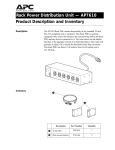
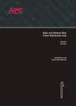
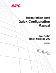
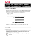
Three-Phase Rack Power
Distribution Unit
AP7601
AP7602
AP7608
Installation and
Operation Manual
Contents
Product Description and Inventory . . . . . . . . . . . . . . . . . . . . . . 1
Description . . . . . . . . . . . . . . . . . . . . . . . . . . . . . . . . . . . . 1
Inventory . . . . . . . . . . . . . . . . . . . . . . . . . . . . . . . . . . . . . 1
How to Install the Rack PDUs . . . . . . . . . . . . . . . . . . . . . . . . . . 3
Installation guidelines . . . . . . . . . . . . . . . . . . . . . . . . . . . . 3
Mounting options . . . . . . . . . . . . . . . . . . . . . . . . . . . . . . . 3
Toolless mounting . . . . . . . . . . . . . . . . . . . . . . . . . . . . . . . 4
Bracket-mounting . . . . . . . . . . . . . . . . . . . . . . . . . . . . . . . 5
Configuration . . . . . . . . . . . . . . . . . . . . . . . . . . . . . . . . . . . . . . 7
How to configure the PDU through a serial port . . . . . . . . . . . 7
Using the menus . . . . . . . . . . . . . . . . . . . . . . . . . . . . . . . . 8
Status Information option . . . . . . . . . . . . . . . . . . . . . . . . . . 8
Rack PDU Configuration option . . . . . . . . . . . . . . . . . . . . . . 9
Device Data option . . . . . . . . . . . . . . . . . . . . . . . . . . . . . . 9
Factory Data option . . . . . . . . . . . . . . . . . . . . . . . . . . . . . 10
Logout option . . . . . . . . . . . . . . . . . . . . . . . . . . . . . . . . . 10
System Management option . . . . . . . . . . . . . . . . . . . . . . . 10
Operation . . . . . . . . . . . . . . . . . . . . . . . . . . . . . . . . . . . . . . . . 11
Display interface . . . . . . . . . . . . . . . . . . . . . . . . . . . . . . . 11
Alarm conditions . . . . . . . . . . . . . . . . . . . . . . . . . . . . . . . 12
Wiring Options . . . . . . . . . . . . . . . . . . . . . . . . . . . . . . . . . . . . 13
Hardwiring procedure (optional) . . . . . . . . . . . . . . . . . . . . 13
Additional power cord available from APC . . . . . . . . . . . . . . 14
Specifications . . . . . . . . . . . . . . . . . . . . . . . . . . . . . . . . . . . . . 15
How to Download Firmware Updates . . . . . . . . . . . . . . . . . . . 16
Warranty and Service . . . . . . . . . . . . . . . . . . . . . . . . . . . . . . . 17
Limited warranty . . . . . . . . . . . . . . . . . . . . . . . . . . . . . . . 17
Warranty limitations . . . . . . . . . . . . . . . . . . . . . . . . . . . . 17
Obtaining service . . . . . . . . . . . . . . . . . . . . . . . . . . . . . . 17
Three-Phase Rack PDU — Installation and Operation Manual
i
Product Description and Inventory
Description
This manual provides information on installing and operating three Rack
PDUs (AP7601, AP7602, and AP7608), which mount vertically in the
rear channel of an APC NetShelter VX Enclosure.
Each of these PDUs has a sensor that measures the current being used by
the PDU and its attached devices. The display interface shows the
aggregate current of an individual phase. An alarm occurs if the
aggregate current is above the high threshold value or below the low
threshold values that you configure. These PDUs have the following
plugs and outlets:
PDU
Plug
Number and Type of Outlets
AP7601
L21-20
42 NEMA 5-20R
AP7602
L21-20
21 NEMA 5-20R and 6 L6-20R
AP7608
L21-20
42 IEC-320-C13
Inventory
Description
Part Number
Quantity
Serial cable
940-0144
1
Hardware end cap
870-70803
1
Hardware access cover
870-70804
1
Note: Bracket kits (AR8116BLK) are available for Rack PDUs.
Three-Phase Rack PDU — Installation and Operation Manual
1
Product Description and Inventory
AP7601
2
AP7602
AP7608
Three-Phase Rack PDU — Installation and Operation Manual
How to Install the Rack PDUs
Installation guidelines
Mounting options
• If the PDU is installed in an enclosed communications rack, the
recommended maximum ambient temperature should be no greater
than 45°C.
• Install the PDU so that the amount of air flow required for safe
operation of the equipment is not compromised.
• Install the PDU so that there is not an uneven mechanical load.
• Follow the nameplate ratings when connecting equipment to the
supply circuit. Take into consideration the effect that overloading
the circuits might have on over-circuit protection and supply
wiring.
• Maintain reliable earthing of the PDU. Give particular
consideration to supply connects that do not directly connect to the
branch circuit.
• Install the PDU so that the power plug may be disconnected for
service.
You can install Rack PDUs in one of two ways: using toolless mounting
pegs or the mounting brackets. The Rack PDU mounts in the rear of the
enclosure, in the channel directly behind the rear vertical mounting rails.
Before you begin to install the Rack PDUs, choose a location in the
enclosure and decide on the mounting method.
Three-Phase Rack PDU — Installation and Operation Manual
3
How to Install the Rack PDUs
Toolless mounting
1. Slide the mounting pegs into the holes provided in the channel in
the rear panel of the enclosure. Make sure the bottom pegs slide
into the bottom holes in the enclosure.
2. Snap the Rack PDU into place by pushing it downward until it
locks into position.
4
Three-Phase Rack PDU — Installation and Operation Manual
How to Install the Rack PDUs
Bracket-mounting
You can order a rack-mount bracket kit from APC—AR8116BLK. You
attach the brackets to the Rack PDU in one of the two directions shown
in the figures in step 1. Consider the orientation of the Rack PDU in the
enclosure before attaching the brackets. A recessed orientation allows
the Rack PDU to be mounted flush with the enclosure; a raised
orientation allows you to route cables through the channel (see the
figures in step 2).
1. Attach two brackets to the rear of the Rack PDU, using six panhead screws (provided in the bracket kit) for each bracket.
– Recessed Orientation
– Raised Orientation
Three-Phase Rack PDU — Installation and Operation Manual
5
How to Install the Rack PDUs
2. Insert one mounting screw (provided with the bracket kit) in the
top and bottom positions in the channel where the brackets align
with the holes. Tighten the screw to secure the Rack PDU to the
enclosure.
– Recessed Orientation
– Raised Orientation
6
Three-Phase Rack PDU — Installation and Operation Manual
Configuration
If you have InfraStruXure Manager as part of your system,
you can use InfraStruXure Manager’s Web interface to
configure the same values that are configured through a
serial port.
Note
How to configure the
PDU through a serial
port
1. Connect an available serial port on your computer to the serial port
on the Rack PDU, using the supplied configuration cable
(990-0144). The PDU’s serial port is shown below.
2. Run a terminal emulation program such as Windows®
HyperTerminal.
3. Configure the following settings for the serial port:
– 19,200 bps
– no parity
– 8 data bits
– 1 stop bit
– no flow control
Note
Some terminal emulation programs require that a
device be disconnected and then reconnected for the
new serial port settings to take effect.
4. Press any key on the computer to display the PDU login screen,
which contains the Username and Password prompts.
5. Log on by using the user name and password for the appropriate
access level:
Access Level
Default User
Name
Default Password
Administrator
Press ENTER.
Type apc (lowercase).
User
Press ENTER.
Press ESC.
Three-Phase Rack PDU — Installation and Operation Manual
7
Configuration
Using the menus
To view a menu, type the associated number and press ENTER.
Users can view all data, but only administrators can configure
parameters.
The main menu has the following options:
Option
Number
Option
Access
1
Status
Information
User and Administrator
2
Rack PDU
Configuration
Users can display the
parameters. Administrators
can configure the
parameters.
3
Device Data
Users can display the
parameters. Administrators
can configure them.
4
Factory Data
User and Administrator
5
Logout
User and Administrator
6
System
Management
Available only when you
are logged in as
Administrator.
Status Information
option
Status Information, main menu option 1, displays the output current, in
amps, for each phase from the PDU and reports if the load is at or above
the configured limits for output current.
8
Three-Phase Rack PDU — Installation and Operation Manual
Configuration
Rack PDU Configuration
option
Rack PDU Configuration, main menu option 2, provides the following
options:
Option
Number
Option
1
Warning and Alarm
Threshold Data for output
current.
2
Audio/Visual Indicator
Settings to enable or disable the
audible alarm and digital
display and to set the
orientation of the display.
Access
Users can display
the parameters.
Administrators can
configure them.
Settings are displayed for each phase.
• To change a warning and alarm threshold, type the number of the
setting, press ENTER, type the new value, and press ENTER again.
• To change an audio/visual indicator setting:
a. Type 1, and press ENTER to move the arrow cursor to the next
setting.
b. Type 2, and press ENTER to change the selected setting.
c. Type the number listed for the setting you want, and press
ENTER.
Device Data option
Device Data, main menu option 3, has the following settings:
D
Setting
Description
Product
Name
A unique name that you
assign to the device.
Product
Location
For example, the enclosure
in which the PDU is
installed.
Contact
Information
For example, a name or
phone number of a person to
contact.
Log
Timeout
(mins)
The number of minutes a
user can be inactive before
being logged off.
Admin
Password
The password of the
Administrator account
(displayed as asterisks to
users).
Access
Users can
display the
parameters.
Administrators
can configure
them.
Three-Phase Rack PDU — Installation and Operation Manual
9
Configuration
To change as setting:
1. Type 1, and press ENTER to move the arrow cursor to the next
setting.
2. Type 2, and press ENTER to change the selected setting.
3. Type the new value, and press ENTER.
Factory Data option
Factory Data, main menu option 4, displays the following information
about the Rack PDU:
• Model number
• Serial number
• Hardware revision
• Date of manufacture
• Firmware revision
• Date on which the firmware was installed
You cannot change any of these items.
Logout option
Logout, main menu option 5, logs you off from the interface.
System Management
option
System Management, main menu option 6, is accessible only when you
are logged in as Administrator.
Type the number of any one of the following options, and press ENTER to
select it.
Option
Number
10
Option
Description
1
Restart
RMPDU
Restarts the PDU while
maintaining the present
settings
2
Restore
Default
Parameters
and Restart
Resets all parameters to their
default settings, and restarts
the PDU
3
Firmware
Download
Prepares to download
firmware. See “How to
Download Firmware
Updates” on page 16.
Three-Phase Rack PDU — Installation and Operation Manual
Operation
Display interface
Control button:
• Press to change the phase of the current displayed on
the digital display.
• Press and hold for five seconds to view the orientation;
hold for an additional five seconds to change the
orientation.
• Press to silence an alarm.
Display of the current used by the PDU and attached
devices:
• Shows the aggregate current for the phase
corresponding to the Phase Indicator LED that is
illuminated.
• Cycles through all three phases in 3-second intervals.
Serial port: Access internal menus by connecting this
port (RJ-11 modular port) to a serial port on your
computer, using the supplied serial cable (part number
940-0144).
Phase indicator LEDs:
• Indicates the phase corresponding to the current listed
in the digital display.
• Indicates normal (green), warning (yellow) or alarm
(red) condition.
Status LED: Indicates the status of the network
connection and the state of the PDU.
Ethernet Port: Connects the PDU to the InfraStruXure
network, using a CAT-5 network cable.
Link LED: Indicates whether there is activity on the
network.
Three-Phase Rack PDU — Installation and Operation Manual
11
Operation
Alarm conditions
You configure warning and alarm limits through the internal menus,
using a serial port connection.
The Rack PDU shows warning and alarm conditions as follows:
Phase Indicator LED
Displays yellow for a warning and red for an
alarm.
Digital Display
If one phase is at or above the warning or
alarm limit, the display shows the current for
that phase.
If more than one phase is at or above the
warning or alarm limit, the display cycles
among those phases, displaying their current.
Control Button
Pressing this button causes the digital display
to display the current for the next phase for 30
seconds. Then it returns to the display of the
current for any phases that are at or above the
warning or alarm limits.
Warning
12
Do not exceed the maximum voltage and
current ratings listed on the rear panel of
the Rack PDU.
Three-Phase Rack PDU — Installation and Operation Manual
Wiring Options
Hardwiring procedure
(optional)
Remove the power cord.
Note
Make sure that power to the Rack PDU has been turned
off, and unplug any attached equipment to prevent damage
if a mistake occurs during wiring.
1. Detach the inspection cover on the power inlet end of the Rack
PDU by removing the four screws on the sides of the cover and
tilting the cover upward so that the terminal block is exposed. Set
the screws aside for later use.
2. Loosen the four screws that hold the power cord’s wires to the
terminal block, and loosen the screw that holds the ground wire to
the standoff on the metal chassis.
3. Pull the power cord and the inspection cover from the Rack PDU.
Attach wiring to terminal block.
4. Attach a 1-inch conduit termination to the hardwiring end cap (part
number 870-70803).
5. Attach the hardwiring end cap assembly to the power inlet end of
the Rack PDU, using two of the screws removed in step 1.
Three-Phase Rack PDU — Installation and Operation Manual
13
Wiring Options
6. Attach wires to the terminal block as labeled on the board. Tighten
the terminal block screws to secure the wires.
Metered Rack-Mount PDU Terminal Block
L3
L2
L1
L3
L2
L1
7. Attach a ground wire to the standoff on the metal chassis and
tighten the screw to secure the ground to the chassis.
8. Place the hardwiring access cover (part number 870-70804) on the
PDU, and secure it with one screw in the hole on the top of the
cover.
9. Apply power to the PDU, observing the status LED on the display
interface. If the unit is connected properly, the LED will
illuminate.
Additional power cord
available from APC
You can also use the power cord AP9870, available for purchase from
APC, with the Rack PDUs described in this manual. This power cord
has the following cord ends (IEC 320 C13 to IEC 320 C14):
14
Three-Phase Rack PDU — Installation and Operation Manual
Specifications
Electrical
AP7601
AP7602
AP7608
100–120/173–208 V, 3φ 16 A
Input
NEMA L21-20 plug; 3 ft power cord
Output
100–120 V, 3×16 A
100–120/173 –208 V,
3×16 A
173–208 V,
3×16 A
42 NEMA 5-20R
receptacles
21 NEMA 5-20R
receptacles;
6 NEMA L6-20R
receptacles
42 IEC 320
receptacles
Physical
Dimensions
1.75 × 3.5 × 60 in (4.5 × 8.9 × 152.4 cm)
Weight
18 lb (8.2 kg)
Shipping
dimensions
4 × 5 × 72 in (10.2 × 12.7 × 182.9 cm)
Shipping weight
20 lb (9.1 kg)
Environmental
Operating
temperature
23 to 113° F (–5 to 45° C)
Operating
humidity
5–95% RH non-condensing
Operating
elevation
10,000 ft (3000 m) above MSL
Storage
temperature
–13 to 149° F (–25 to 65° C)
Storage humidity
5–95% RH non-condensing
Compliance
Approvals
UL, CUL, FCC, VCCI
Three-Phase Rack PDU — Installation and Operation Manual
15
How to Download Firmware Updates
You can use a local computer that connects to the Rack PDU through the
serial port on the front of the unit.
1. Select a serial port at the local computer, and disable any service
that uses that port.
2. Use the configuration cable to connect the selected port to the
RJ-12 serial port on the front panel of the Rack PDU.
3. Run a terminal program (such as HyperTerminal) and configure
the selected port for 9600 bps, 8 data bits, no parity, 1 stop bit, and
no flow control. Save the changes.
4. Press ENTER twice to display the User Name prompt.
5. Enter your User Name and Password (both apc, for administrators
only) and press the ENTER key.
6. From the Control Console menu, select System, then Tools, then
XMODEM.
7. The system will prompt you with Perform transfer with
XMODEM -CRC? Type Yes and press ENTER.
8. The system will then prompt you to choose a transfer rate and to
change your terminal settings to match the transfer rate. Press
ENTER to set the Rack PDU to accept the download.
9. In the terminal program, send the file using the XMODEM
protocol. Upon completion of the transfer, the console will prompt
you to restore the baud rate to normal.
Do not interrupt the download.
Caution
The Rack PDU will reboot when the download is complete.
Upgrading the firmware will not interfere with the
operation of the outlets.
Note
16
Three-Phase Rack PDU — Installation and Operation Manual
Warranty and Service
Limited warranty
APC warrants the PDU to be free from defects in materials and
workmanship for a period of two years from the date of purchase. Its
obligation under this warranty is limited to repairing or replacing, at its
own sole option, any such defective products. This warranty does not
apply to equipment that has been damaged by accident, negligence, or
misapplication or has been altered or modified in any way. This
warranty applies only to the original purchaser.
Warranty limitations
Except as provided herein, APC makes no warranties, express or
implied, including warranties of merchantability and fitness for a
particular purpose. Some jurisdictions do not permit limitation or
exclusion of implied warranties; therefore, the aforesaid limitation(s) or
exclusion(s) may not apply to the purchaser.
Except as provided above, in no event will APC be liable for direct,
indirect, special, incidental, or consequential damages arising out of
the use of this product, even if advised of the possibility of such
damage.
Specifically, APC is not liable for any costs, such as lost profits or
revenue, loss of equipment, loss of use of equipment, loss of software,
loss of data, costs of substitutes, claims by third parties, or otherwise.
This warranty gives you specific legal rights and you may also have
other rights, which vary according to jurisdiction.
Obtaining service
To obtain support for problems with your PDU:
0
1. Note the serial number and date of purchase. The serial number is
located on the bottom of the PDU.
2. Contact Customer Support at a phone number located on the back
cover of this manual. A technician will try to help you solve the
problem by phone.
3. If you must return the product, the technician will give you a return
material authorization (RMA) number. If the warranty expired, you
will be charged for repair or replacement.
4. Pack the unit carefully. The warranty does not cover damage
sustained in transit. Enclose a letter with your name, address, RMA
number and daytime phone number; a copy of the sales receipt;
and a check as payment, if applicable.
5. Mark the RMA number clearly on the outside of the shipping
carton.
6. Ship by insured, prepaid carrier to the address provided by the
Customer Support technician.
Three-Phase Rack PDU — Installation and Operation Manual
17
Radio Frequency Interference
Warning
Changes or modifications to this unit not
expressly approved by the party
responsible for compliance could void the
user’s authority to operate this
equipment.
This equipment has been tested and found to comply with the limits for a
Class A digital device, pursuant to part 15 of the FCC Rules. These
limits are designed to provide reasonable protection against harmful
interference when the equipment is operated in a commercial
environment. This equipment generates, uses, and can radiate radio
frequency energy and, if not installed and used in accordance with this
user manual, may cause harmful interference to radio communications.
Operation of this equipment in a residential area is likely to cause
harmful interference. The user will bear sole responsibility for
correcting such interference.
This Class A digital apparatus complies with Canadian ICES-003.
Cet appareil numérique de la classe A est conforme à la norme NMB003 du Canada.
a
APC Worldwide Customer Support
Customer support for this or any other APC product is available at no charge in any of the following ways:
• Visit the APC Web site to find answers to frequently asked questions (FAQs), to access documents
in the APC Knowledge Base, and to submit customer support requests.
– www.apc.com (Corporate Headquarters)
Connect to localized APC Web sites for specific countries, each of which provides customer
support information.
– www.apc.com/support/
Global support with FAQs, knowledge base, and e-support.
• Contact an APC Customer Support center by telephone or e-mail.
– Regional centers:
APC headquarters U.S., Canada
Latin America
Europe, Middle East, Africa
Japan
(1)(800)800-4272 (toll free)
(1)(401)789-5735 (USA)
(353)(91)702020 (Ireland)
(0) 35434-2021
– Local, country-specific centers: go to www.apc.com/support/contact for contact information.
Contact the APC representative or other distributor from whom you purchased your APC product for
information on how to obtain local customer support.
Entire contents copyright © 2003 American Power Conversion. All rights reserved.
Reproduction in whole or in part without permission is prohibited. APC, the APC logo,
InfraStruXure, and NetShelter are trademarks of American Power Conversion Corporation
and may be registered in some jurisdictions. All other trademarks, product names, and
corporate names are the property of their respective owners and are used for informational
purposes only.
990-1506
05/2003