1
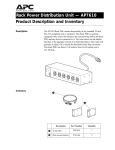
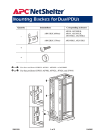
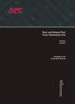
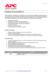
Power Distribution
Unit (PDU)
AP7620
AP7621
AP7622
AP7626
User’s Manual
®
This manual is available in English on the enclosed CD.
❖❖❖
Dieses Handbuch ist in Deutsch auf der beiliegenden
CD-ROM verfügbar.
❖❖❖
Este manual está disponible en español en el CD-ROM
adjunto.
❖❖❖
Ce manuel est disponible en français sur le CD-ROM
ci-inclus.
❖❖❖
Questo manuale è disponibile in italiano nel CD-ROM
allegato.
Contents
Product Descriptions and Safety Information . . . . . 1
Installation . . . . . . . . . . . . . . . . . . . . . . . . . . . . . . 6
Operation . . . . . . . . . . . . . . . . . . . . . . . . . . . . . . 11
Configuration . . . . . . . . . . . . . . . . . . . . . . . . . . . 12
Downloading the Latest Firmware Revision. . . . . 17
Specifications . . . . . . . . . . . . . . . . . . . . . . . . . . . 18
Warranty and Service . . . . . . . . . . . . . . . . . . . . . 22
Life-Support Policy . . . . . . . . . . . . . . . . . . . . . . . 24
PDU: User’s Manual
Product Descriptions and Safety Information
Features of
single-branch
PDU models
This manual explains how to install and use the following
Rack-mount PDUs:
PDU
Voltage
Number of
Outlets
Outlet Type
AP7620
100–120 VAC
24
NEMA 5-20R
AP7622
200–240 VAC
6
NEMA L6-20R
21 outlets of type
AP7621
AP7626
200–240 VAC
25
IEC 320 C13
4 outlets of type
IEC 320 C19
All the PDUs distribute input power from a single source to the
PDU outlets for use by connected equipment and provide
current-sensing to guard against overload conditions.
Safety
information
In all applications, the plug on the power supply
cord is the means to disconnect the PDU. The
receptacle (outlet) into which the PDU is plugged
must be installed near the connected equipment
and must be easily accessible.
In 208 and 230 VAC applications, the PDU relies
on the building installation for over-current and
short-circuit current protection.
Note
You must connect the PDU to a branch circuit
that is rated as follows:
• 20 amps, 250 volts (in accordance with
NFPA 70) in 208 VAC applications.
• 16 amps, 250 volts in 230 VAC
applications.
PDU: User’s Manual
1
Product Descriptions and Safety Information
120V PDU
➊
➋
➌
➍
➎
➏
➐
! Rack-mount PDU (AP7620)
" Display interface
# NEMA 5-20R outlets (24)
$ Cord retainer holes
% NEMA L5-20 power cord
& Serial cable
' Cord retainer
2
PDU: User’s Manual
Product Descriptions and Safety Information
208V PDU
➊
➋
➌
➍
➎
! Rack-mount PDU (AP7622)
" Display interface
# NEMA L6-20R outlets (6)
$ NEMA L6-20 power cord
% Serial Cable
PDU: User’s Manual
3
Product Descriptions and Safety Information
230V PDU with
IEC 320 C20
power cord
➊
➋
➌
➍
➎
➏
➐
➑
! Rack-mount PDU (AP7621)
" IEC C13 outlets (21)
# IEC C19 outlets (4)
$ Display interface
% Cord retainer holes
& IEC 320 C20 power cord
' Serial cable
( Cord retainers (21 short, for use at the C13 outlets; 4
long, for use at the C19 outlets)
4
PDU: User’s Manual
Product Descriptions and Safety Information
230V PDU with
NEMA L6-20
power cord
➊
➋
➌
➍
➎
➏
➐
➑
! Rack-mount PDU (AP7626)
" IEC C13 outlets (21)
# IEC C19 outlets (4)
$ Display interface
% Cord retainer holes
& NEMA L6-20 power cord
' Serial cable
( Cord retainers (21 short, for use at the C13 outlets; 4
long, for use at the C19 outlets)
PDU: User’s Manual
5
Installation
Mounting
options
You can install Rack-mount PDUs in one of two ways: using
toolless mounting pegs or the mounting brackets. You mount
the Rack-mount PDUs in the rear of the enclosure, in the
channel directly behind the rear vertical mounting rails. Before
you begin to install the Rack-mount PDUs, choose a location
for them in the enclosure and decide on the mounting method.
6
PDU: User’s Manual
Installation
Toolless
mounting
1. Decide where to mount the PDU and whether the power
cord will be at the upper or lower end of the PDU.
Caution
Make sure that the power cord can reach an
outlet easily, does not interfere with other
equipment, and does not bend sharply.
• In a PowerStruXure Type A system,
you must mount the PDU so that its
power cord is at the lower end.
• In any system, if you orient the PDU
so that the power cord is at the lower
end, do not mount the PDU in the
lowest position possible in the
enclosure.
2. Slide the mounting pegs into a set of holes in the channel
PDU: User’s Manual
7
Installation
in the rear panel of the enclosure.
3. Push the PDU downward until it locks into position.
.
8
PDU: User’s Manual
Installation
Bracketmounting
You can order a rack-mount bracket kit from APC—
AR8116BLK. The brackets attach to the Rack-mount PDU in
two different directions, shown in the figures in step 1.
Consider the orientation of the Rack-mount PDU in the
enclosure before attaching the brackets. A recessed orientation
allows the Rack-mount PDU to be mounted flush with the
enclosure; a raised orientation allows you to route cables
through the channel (see the figures in step 2).
1. Attach two brackets to the rear of the Rack-mount PDU,
using six pan-head screws (provided in the bracket kit)
for each bracket.
– Recessed Orientation
– Raised Orientation
2. Insert one mounting screw (provided with the bracket kit)
in the top and bottom positions in the channel where the
PDU: User’s Manual
9
Installation
brackets align with the holes. Tighten to secure the Rackmount PDU to the enclosure.
– Recessed Orientation
– Raised Orientation
10
PDU: User’s Manual
Operation
Rack-mount
PDU display
interface
!
"
#
$
Control
Button
To view the orientation of the LED display,
press and hold the button for 5 seconds
To change the orientation, hold the button for
an additional 5 seconds until “AA” flashes
and then changes orientation.
To silence an alarm, press the button.
" LED display
Displays the current that is drawn by the load
equipment.
# Serial Port
Provides the connection to access the internal
configuration menus.
$
Alerts you to warning and alarm conditions:
• normal: green
• warning: yellow
• alarm: red
!
Line LED
PDU: User’s Manual
11
Configuration
Using a serial
port connection
0
1. Connect an available serial port of your computer to the
serial port on the front panel of the PDU, using the
supplied serial cable.
2. Run a terminal emulation program such as Windows®
HyperTerminal.
3. Configure the following settings for the serial port:
– 19,200 bps
– no parity
– 8 data bits
– 1 stop bit
– no flow control
Note
Some terminal emulation programs require
that a device be disconnected and then
reconnected for the new serial port settings
to take effect.
4. Press any key on the computer to display the PDU login
screen, which contains the Username and Password
prompts.
5. Log on by using the user name and password for the
appropriate access level:
12
Access Level
Default User
Name
Default Password
Administrator
Press ENTER.
Type apc (in lowercase).
User
Press ENTER.
Press ESC.
PDU: User’s Manual
Configuration
Access to menus
When you log in as User, you can view information but cannot
configure settings or enter data.
When you log in as Administrator, you can view information,
configure settings, and enter data. Any changes take effect
immediately.
To navigate the menus and their options, type the number of
the selection you want, and press ENTER.
PDU: User’s Manual
13
Configuration
Main menu
Menu
Number
Status
Information
option
Option Name
Access
1
Status Information
Administrator and User
2
Metered Rack-Mount
PDU Configuration
Administrator and User
3
Device Data
Administrator and User
4
Factory Data
Administrator and User
5
Logout
Administrator and User
6
System Management
Administrator only (The
menu is not displayed when
you are logged on as User
Choosing this option displays the following information about
the PDU.
• The current in amps
• The status (whether it is within the configured limits for
output current or has reached or exceeded those limits).
This option includes no items configurable through this screen.
Metered RackMount PDU
Configuration
option
14
Choosing this option displays the following additional options.
Option
Number
Option Name
1
Warning and Alarm
Threshold Data
2
Audio/Visual
Indicator Settings
PDU: User’s Manual
Access
Administrator has
configuration access.
User has display access only.
• Type 1 and press ENTER
to move to the next item
• Type 2 and press ENTER
to change the item.
Configuration
Device Data
option
Choosing this option displays the following information:
Item
Factory Data
option
Definition
Product
Name
The name of the
product, such as
Rack-mount PDU.
Product
Location
Where this PDU is
located, such as
Rack 4.
Contact
Information
Whom to contact
about this PDU.
Log
Timeout
(mins)
The number of
minutes of
inactivity that is
permitted before
you are logged out
automatically.
Admin
Password
The password
required to log on
as Administrator.
When logged on
as User, you can
not view this
password.
Access
Administrator has
configuration access.
• Type 1 and press
ENTER to move to the
next item
• Type 2 and press
ENTER to change the
item.
User has display access only.
Choosing this option displays the following information about
the PDU.
• The model number
• The serial number
• The hardware revision
• The date of manufacture
• The firmware revision
• The date the firmware was installed.
This option includes no configurable items.
PDU: User’s Manual
15
Configuration
System
Management
option
Choosing this option displays the following additional options
Menu
Number
1
16
Menu
Name
Restart
RMPDU
Definition
Restart the PDU,
using the parameters
that are currently
configured.
2
Restore
Parameters
and Restart
Restart the PDU,
using the default
values for all
parameters.
3
Firmware
Download
Prepare to download
new firmware
PDU: User’s Manual
Access
This menu
option is
displayed only
if you are
logged on as
Administrator.
Downloading the Latest Firmware Revision
How to
download
firmware to a
Rack-mount
PDU
During firmware downloads, power will not be
interrupted to the PDU outlets.
Note
1. Go to www.apcc.com/tools/download/, and check to see
if there is a version of firmware for your type of Rackmount PDU later than the version you are currently
using.
2. Access the PDU internal menus through a serial port
connection.
See “Using a serial port connection” on page 12.
3. Log on to the Rack-mount PDU as an Administrator.
4. Type 6 (for System Management) on the Main menu
and press ENTER.
5. Type 3 (for Firmware Download) on the System
Management menu, and press ENTER.
6. From the Firmware Download menu:
a. Type 1 and press ENTER to initiate a download. The
menu displays C repeatedly and the display interface
displays dL.
b. Select the Transfer pull-down menu from the menu
bar.
c. Select Send File from the Transfer pull-down menu.
d. Browse for and select the firmware file you copied to
your computer.
e. Set the protocol to Xmodem and press the Send
button.
When the firmware download is complete, the display interface
refreshes and displays the current in amps.
PDU: User’s Manual
17
Specifications
AP7620
Electrical Specifications
Input
100–120 V; 50–60 Hz; 16 A
Output
100–120 V; 50–60 Hz; 16 A
Physical Specifications
Dimensions
1.75 × 3.5 × 48 in
4.5 × 8.9 × 121.9 cm
Weight
11.75 lb
5.3 kg
Shipping dimensions
3.75 × 5.0 × 60 in
9.5 × 12.7 × 152.4 cm
Shipping weight
15.0 lb (6.8 kg)
Operating temperature
23 to 113° F (-5 to 45° C)
Operating humidity
5–95% RH non-condensing
Operating elevation
10,000 ft (3000 m) above MSL
Storage temperature
-13 to 149° F (-25 to 65° C)
Storage humidity
5–95% RH non-condensing
Compliance Specifications
Approvals
18
PDU: User’s Manual
UL, cUL, FCC, VCCI
Specifications
AP7621
Electrical Specifications
Input
200–240 V; 50–60 Hz; 16 A
Output
200–240 V; 50–60 Hz; 10 A (IEC C13
outlets); 16 A (IEC C19 outlets)
Physical Specifications
Dimensions
1.75 × 3.5 × 48 in
4.5 × 8.9 × 121.9 cm
Weight
13.0 lb
5.9 kg
Shipping dimensions
3.75 × 5.0 × 60 in
9.5 × 12.7 × 152.4 cm
Shipping weight
14.5 lb (6.6 kg)
Operating temperature
23 to 113° F (-5 to 45° C)
Operating humidity
5–95% RH non-condensing
Operating elevation
10,000 ft (3000 m) above MSL
Storage temperature
-13 to 149° F (-25 to 65° C)
Storage humidity
5–95% RH non-condensing
Compliance Specifications
Approvals
PDU: User’s Manual
VDE, CE, VCCI
19
Specifications
AP7622
Electrical Specifications
Input
200–240 V; 50–60 Hz; 16 A
Output
200–240 V; 50–60 Hz; 16 A
Physical Specifications
Dimensions
1.75 × 3.5 × 48 in
4.5 × 8.9 × 121.9 cm
Weight
14.0 lb
6.4 kg
Shipping dimensions
3.75 × 5.0 × 60 in
9.5 × 12.7 × 152.4 cm
Shipping weight
15.5 lb
7.0 kg
Operating temperature
23 to 113° F (-5 to 45° C)
Operating humidity
5–95% RH non-condensing
Operating elevation
10,000 ft (3000 m) above MSL
Storage temperature
-13 to 149° F (-25 to 65° C)
Storage humidity
5–95% RH non-condensing
Compliance Specifications
Approvals
20
PDU: User’s Manual
UL, cUL, FCC, VCCI
Specifications
AP7626
Electrical Specifications
Input
200–240 V; 50–60 Hz; 16 A
Output
200–240 V; 50–60 Hz; 10 A (IEC C13
outlets); 16 A (IEC C19 outlets)
Physical Specifications
Dimensions
1.75 × 3.5 × 48 in
4.5 × 8.9 × 121.9 cm
Weight
13.0 lb
5.9 kg
Shipping dimensions
3.75 × 5.0 × 60 in
9.5 × 12.7 × 152.4 cm
Shipping weight
14.5 lb (6.6 kg)
Operating temperature
23 to 113° F (-5 to 45° C)
Operating humidity
5–95% RH non-condensing
Operating elevation
10,000 ft (3000 m) above MSL
Storage temperature
-13 to 149° F (-25 to 65° C)
Storage humidity
5–95% RH non-condensing
Compliance Specifications
Approvals
PDU: User’s Manual
UL, cUL, FCC, VCCI
21
Warranty and Service
Limited
warranty
APC warrants the Power Distribution Unit to be free from
Warranty
limitations
Except as provided herein, APC makes no warranties,
express or implied, including warranties of merchantability
and fitness for a particular purpose. Some jurisdictions do
not permit limitation or exclusion of implied warranties;
therefore, the aforesaid limitation(s) or exclusion(s) may not
apply to the purchaser.
defects in materials and workmanship for a period of two years
from the date of purchase. Its obligation under this warranty is
limited to repairing or replacing, at its own sole option, any
such defective products. This warranty does not apply to
equipment that has been damaged by accident, negligence, or
misapplication or has been altered or modified in any way. This
warranty applies only to the original purchaser.
Except as provided above, in no event will APC be liable for
direct, indirect, special, incidental, or consequential
damages arising out of the use of this product, even if
advised of the possibility of such damage.
Specifically, APC is not liable for any costs, such as lost profits
or revenue, loss of equipment, loss of use of equipment, loss of
software, loss of data, costs of substitutes, claims by third
parties, or otherwise. This warranty gives you specific legal
rights and you may also have other rights, which vary
according to jurisdiction.
Obtaining
service
To obtain support for problems with your Power Distribution
Unit:
0
1. Note the serial number and date of purchase. The serial
number is on a label on the back of the PDU.
2. Contact Customer Support at a phone number on the
back cover of this document. A technician will try to
help you solve the problem by phone.
3. If you must return the product, the technician will give
you a return material authorization (RMA) number. If the
warranty expired, you will be charged for repair or
22
PDU: User’s Manual
replacement.
4. Pack the unit carefully. The warranty does not cover
damage sustained in transit. Enclose a letter with your
name, address, RMA number and daytime phone
number; a copy of the sales receipt; and a check as
payment, if applicable.
5. Mark the RMA number clearly on the outside of the
shipping carton.
6. Ship by insured, prepaid carrier to the address provided
by the Customer Support technician.
PDU: User’s Manual
23
Life-Support Policy
General policy
American Power Conversion (APC) does not recommend the
use of any of its products in the following situations:
• In life-support applications where failure or malfunction
of the APC product can be reasonably expected to cause
failure of the life-support device or to affect significantly
its safety or effectiveness.
• In direct patient care.
APC will not knowingly sell its products for use in such
applications unless it receives in writing assurances
satisfactory to APC that (a) the risks of injury or damage have
been minimized, (b) the customer assumes all such risks, and
(c) the liability of American Power Conversion is adequately
protected under the circumstances.
a
Examples of
life-support
devices
The term life-support device includes but is not limited to
neonatal oxygen analyzers, nerve stimulators (whether used for
anesthesia, pain relief, or other purposes), autotransfusion
devices, blood pumps, defibrillators, arrhythmia detectors and
alarms, pacemakers, hemodialysis systems, peritoneal dialysis
systems, neonatal ventilator incubators, ventilators (for adults
and infants), anesthesia ventilators, infusion pumps, and any
other devices designated as “critical” by the U.S. FDA.
Hospital-grade wiring devices and leakage current protection
may be ordered as options on many APC UPS systems. APC
does not claim that units with this modifications are certified or
listed as hospital-grade by APC or any other organization.
Therefore these units do not meet the requirements for use in
direct patient care.
a
24
PDU: User’s Manual
Radio Frequency Interference
Warning
Changes or modifications to this unit not
expressly approved by the party responsible
for compliance could void the user’s authority
to operate this equipment.
This equipment has been tested and found to comply with the
limits for a Class A digital device, pursuant to part 15 of the
FCC Rules. These limits are designed to provide reasonable
protection against harmful interference when the equipment is
operated in a commercial environment. This equipment
generates, uses, and can radiate radio frequency energy and, if
not installed and used in accordance with this user manual,
may cause harmful interference to radio communications.
Operation of this equipment in a residential area is likely to
cause harmful interference. The user will bear sole
responsibility for correcting such interference.
This Class A digital apparatus complies with Canadian
ICES-003.
Cet appareil numérique de la classe A est conforme à la norme
NMB-003 du Canada.
a
®
APC Worldwide Customer Support
Customer support for this or any other APC product is available at no charge in any of the
following ways:
•
Visit the APC Web site to find answers to frequently asked questions (FAQs), to
access documents in the APC Knowledge Base, and to submit customer support
requests.
– www.apc.com (Corporate Headquarters)
Connect to localized APC Web sites for specific countries, each of which
provides customer support information.
– www.apc.com/support/
Global support with FAQs, knowledge base, and e-support.
•
Contact an APC Customer Support center by telephone or e-mail.
– Regional centers:
APC headquarters U.S.,
Canada
–
(1)(800)800-4272 (toll free)
Latin America
(1)(401)789-5735 (USA)
Europe, Middle East, Africa
(353)(91)702020 (Ireland)
Japan
(03)5434-2021 Guidance 3
Local, country-specific centers: go to www.apc.com/support/contact for
contact information.
Contact the APC representative or other distributor from whom you purchased your APC
product for information on how to obtain local customer support.
Entire contents copyright © 2002 American Power Conversion. All rights
reserved. Reproduction in whole or in part without permission is prohibited.
APC, the APC logo, and PowerStruXure are trademarks of American Power
Conversion Corporation and may be registered in some jurisdictions. All other
trademarks, product names, and corporate names are the property of their
respective owners and are used for informational purposes only.
990-0565A
03/2002