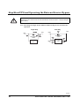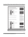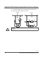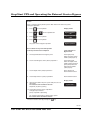
1
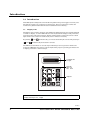
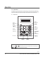
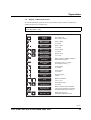
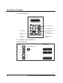
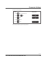
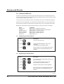
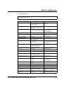
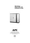
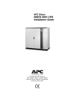
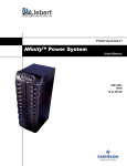
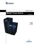
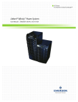
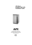
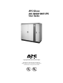
APC Silcon
240-320kW 480V UPS
User Guide
Copyright ©2000 APC Denmark ApS
Information in this document is subject to
change without notice and does not represent a
commitment on the part of the vendor
Thank You
Thank you for chosing APC Silcon UPS. Please read this User Guide thoroughly prior to installing
the system. It provides important information on safe and efficient installation and use.
The installation and use of this product must comply with national, federal, state, municipal and
local codes.
Safety Symbols used in this manual
WARNING!
Indicates a hazard which, if not avoided, could result in injury or death.
CAUTION!
Indicates a hazard which, if not avoided, could result in damage to the product or
other property.
NOTICE!
Read and pay attention to this important information.
WARNING!
This UPS unit contains hazardous AC and DC voltages. Only qualified electricians should connect the
UPS, AC line and external batteries, and must be familiar with batteries and battery installation.
Before installing, maintaining or servicing the UPS, shut off the UPS and disconnect all sources of AC
and DC power.
As the UPS has no built-in disconnection devices to switch off external AC and DC input power, ensure
that disconnection devices are available as separate parts in connection with the installation!
The installer must provide each external disconnecting device for this UPS system with labels with the
following text:
“Isolate the Uninterruptible Power Supply (UPS) as instructed in this guide before working on circuit”
AC and/or DC voltage will always involve a potential risk of AC voltage at UPS output generated from
either batteries or utility. To avoid equipment damage or personal injury, always assume that there
may be voltage at UPS output.
This system is equipped with an auto-start function. If activated, the system may start without warning.
Refer to the “Programming” section for information on de-activation.
TEST BEFORE YOU TOUCH!
To reduce the risk of fire or electric shocks, install the UPS and external batteries in a temperature and
humidity controlled indoor area, free of conductive contaminants.
UPS batteries are high-current sources. Shorting battery terminals, DC terminals or DC busbars can
cause severe arcing, equipment damage and injury. A short circuit can cause a battery to explode.
Always wear protective clothing and eye protection and use insulated tools when working on batteries.
CAUTION!
This unit contains components sensitive to electrostatic discharge (ESD). If you do not follow the ESD
procedures, you may cause severe damage to electronic components.
PLEASE RECYCLE
The shipping materials for the APC Silcon UPS are recyclable. Please save for later use or dispose of
them appropriately.
990-4039
2
User Guide APC Silcon 240-320kW 480V UPS
Contents:
1.0
Introduction
1.1
Display Unit
4
4
2.0
Stop/Start UPS and Operating the External Service Bypass Panel
2.1
Stop UPS (for stand-by)
2.2
Start UPS (from stand-by)
2.3
Stop UPS (for complete power down)
2.3.1 Switching off the UPS
2.4
Start UPS (from complete power down)
2.4.1 UPS Start-up
2.5
Operating the External Service Bypass Switch (single systems)
2.5.1 Bypassing the Single System UPS
2.5.2 Switching the Single System UPS from External Bypass into
Normal UPS Operation
2.6
Operating the External Service Bypass Switch (parallel systems)
2.6.1 Bypassing the Parallel UPS System (All UPSs)
2.6.2 Switching the Parallel System from External Bypass into
Normal UPS Operation
2.7
Isolating one UPS in a Parallel Configuration for
Service/Maintenance
2.7.1 Isolating one UPS in a Parallel/Redundant System
2.7.2 Switching Back the UPS to Normal Parallel/Redundant Operation
5
5
5
6
6
7
7
9
9
16
16
16
3.0
Operation
3.1
Keyboard
3.2
Display of Measured Values
3.3
Using the Remote Display
3.4
Economy Mode
18
18
19
20
20
4.0
Parameter Settings
4.1
Programming Keys
4.2
Switching to Bypass Operation
21
22
22
5.0
Alarms and Events
5.1
Displaying the Alarm Stack
5.2
Displaying the Event Stack
5.3
Possible alarms
5.4
Rectifying Alarm Messages
5.5
Parallel Operation Alarms
24
24
24
25
27
27
6.0
Maintenance & Testing
6.1
Fan
6.2
Battery Monitoring Test
6.3
Battery Capacity Test
28
28
28
28
7.0
Warranty
7.1
APC Silcon UPS Limited Factory Warranty
30
30
8.0
How to Contact APC
31
10
12
12
14
990-4039
User Guide APC Silcon 240-320kW 480V UPS
3
Introduction
1.0 Introduction
This UPS system is designed to offer reliable and problem-free power supply for several years.
The system requires only a minimum of maintenance, but we recommend you follow the
maintenance guidelines described in Section 6.0 Maintenance & Testing.
1.1
Display Unit
The display unit (located on the front of the UPS) is the link between the user and the UPS and
consists of a display, an alarm LED indicator and a keyboard. The display reads parameters,
measured values and alarm messages. Alarms and the pressing of keys will activate a back
light which is set to switch off automatically after 5 minutes of inactivity.
By pressing
and
and
simultaneously you increase the back light contrast. The pressing of
simultaneously decreases the contrast.
The LED alarm is linked to an acoustic signal indicating incorrect operation. Alarms will
change the LED light from green to red. Use keyboard to program operating parameters and
to display parameters / alarm messages.
LCD-display with
back light
Alarm LED
Green: OK
Red: Alarm
Keyboard
NOTICE!
Display accuracy is ±2%, ±1digit.
990-4039
4
User Guide APC Silcon 240-320kW 480V UPS
Stop/Start UPS and Operating the External Service Bypass
2.0 Stop/Start UPS and Operating the External Service Bypass
Panel
WARNING!
AC voltage generated either from batteries or utility, may be present at UPS output.
Always disconnect AC input supply source, switch off UPS, AND switch off DC.
TEST BEFORE YOU TOUCH!
Some UPS systems have a factory-set autostart feature, automatically switching on UPS
whenever utility supply is switched on (AC line). See section 4.0 Parameter Settings for
instructions on how to switch off this function.
Only qualified electricians should start up or shut down UPS systems and instructions in the
Installation Guide should be followed. Prior to being serviced, the UPS must be left in shutdown mode for a minimum of 5 minutes.
CAUTION!
Refer to the Maintenance & Testing section in this guide if the UPS is to be taken out of
operation for more than 48 hours
Users without electrical qualifications may switch UPS to and from stand-by-mode/normal
operation, following instructions below. (In stand-by mode, the UPS has no output
voltage).
2.1
Stop UPS (for stand-by)
CAUTION!
If the UPS system is equipped with a service bypass panel, and if the load must remain
energized by utility, refer to the Operating Service Bypass Panel sections in this guide before
proceeding
Action
Open the front door
and activate red "OFF"
push-button.
2.2
Display shows
System off
Description
The red alarm LED lights up.
Acoustic alarm sounds
for 30 seconds
Start UPS (from stand-by)
Action
Open the front door
and activate the green
"ON" push button
Display shows
Normal operation
Load power xx%
990-4039
User Guide APC Silcon 240-320kW 480V UPS
5
Stop/Start UPS and Operating the External Service Bypass
2.3
Stop UPS (for complete power down)
2.3.1 Switching off the UPS
CAUTION!
If the UPS system is equipped with a Service Bypass Panel, and if the load must remain
energized by utility, refer to the Operating Service Bypass Panel sections in this guide before
proceeding
Green / ON
Red / OFF
WARNING!
TEST BEFORE YOU TOUCH!
A special design feature switches the system into bypass operation in the event of internal power
supply failure or controller circuit failure to ensure uninterrupted output voltage.
Because of this special feature, the UPS may contain output voltage even when it is switched off.
1. Open front doors
2. Note that step 3 will interrupt output voltage and activate the alarm!
The red LED alarm below the display will light up
The acoustic alarm will sound for 30 seconds*
Display shows
3. Press the red OFF button.
The red LED alarm below the display will light up
**System OFF**
The acoustic alarm will sound for 30 seconds*
4. On systems with no Service Bypass Panel, switch off the utility
supply
**System OFF**
5. The red LED alarm below the display will light up
The acoustic alarm will sound for 30 seconds
6. Switch off battery breakers F001 and F002 in the Battery Breaker
Box or battery cabinet
Refer to LED indication and labelling in Battery Breaker Box or
battery cabinet
7. To switch off utility supply, open Q001 – on systems with
Service Bypass Panel.
8. The acoustic alarm sounds
*Reset the acoustic alarm by pressing
Blank
.
990-4039
6
User Guide APC Silcon 240-320kW 480V UPS
Stop/Start UPS and Operating the External Service Bypass
The UPS is now isolated. Maintenance/repair, disconnection or removal can now be carried out.
CAUTION!
Recharge batteries out of service every 3 months to prevent damage.
WARNING!
Internal DC capacitor may contain energy even after the UPS has been switched off. Allow for
automatic discharge by waiting at least 5 minutes after switching off UPS and battery breakers
before working on the UPS.
2.4
Start UPS (from complete power down)
2.4.1 UPS Start-up
CAUTION!
Make sure all cable connections are in place prior to first start-up.
Green / ON
Red / OFF
NOTICE!
After first system start-up, check that battery temperature is displayable (press
and
simultaneously on the display – it reads NV (not valid) if incorrectly installed). A battery capacity
test is recommended after the electric installation.
NOTICE!
If for any reason the start-up procedure is interrupted, wait for the display to show the step 4
message: “Stop charge DC capacitors : YES” and repeat procedure from there.
CAUTION!
Do not close the MCCBs in the Battery Breaker Box unless the display reads: “Close MCCB” otherwise the UPS may be damaged. If the display reads “DC capacitor charge error”, do not
close MCCB.
Call for assistance.
990-4039
User Guide APC Silcon 240-320kW 480V UPS
7
Stop/Start UPS and Operating the External Service Bypass
WARNING!
If “Autostart” is active the UPS will start automatically after step 9 (with a 1-minute delay).
1. Check that the system has been in a stable environment for at least 12 hours enabling
any condensation to evaporate prior to start-up.
2. Open front door(s)
Display shows
3. Switch on utility power by closing Q001 and Q010,
if dual utility
System type XXX
XXX kVA - XXX
4. Wait for approx. 10 seconds
Stop charge DC
capacitors : YES
5. Press
on the keyboard
Start charge DC
capacitors : YES
6. Press
on the keyboard
Data stored
7. Wait for approx. 1 second
Start charge DC
capacitors : YES
8. Wait for approx. 1 minute
Insert fuse or
close MCCB
9. Close MCCBs in battery breaker Box or Battery Cabinet
10. Press the green ON button
**System OFF**
Normal operation
load power XX%
11. Close the front door(s)
System start-up now completed.
NOTICE!
One of the following display messages will appear by UPS start-up:
• “STD”: Standard (single system)
• “PAR”: Parallel System
• “ECO”: Economy mode (single or parallel systems)
(Last message has priority over the other two)
kVA size (XXX) and the voltage reads:
• XXXkVA - 208 (220 or 480 Volt)
990-4039
8
User Guide APC Silcon 240-320kW 480V UPS
Stop/Start UPS and Operating the External Service Bypass
2.5
Operating the External Service Bypass Switch (single systems)
2.5.1 Bypassing the Single System UPS
Dual Utility
Single Utility
Load
Utility
Load
Utility 2
Service Bypass
Switch
Service Bypass
Switch
APC Silcon
UPS
Utility 1
APC Silcon
UPS
Display shows
Action
1. Press
on the keyboard
2. Press
or
3. Press
on the keyboard
4. Press
on the keyboard
on the keyboard until
Bypass operation
: NO
Bypass operation
: YES
Lamp indication on
Bypass Panel
5. Check light indication on the bypass panel
Green light (H003)
above the bypass switch
handle (Q003) lights up
6. Set the external bypass switch (Q003) to position 1
Green light (H002)
above the output switch
handle (Q002) lights up
7. Set the output switch (Q002) to position 0
Only the light (H002)
above the output switch
handle (Q002) is now on
Display shows
8. Open the front door and press the red OFF button.
The acoustic alarm sounds for 30 seconds*
**System OFF**
9. Set the input switch (Q001) to position 0.
Set the bypass input switch (Q010) to position 0 (dual
utility).
The red alarm LED below the display lights up and
the acoustic alarm sounds for 30 seconds*
*Use the
key to reset the acoustic alarm
990-4039
User Guide APC Silcon 240-320kW 480V UPS
9
Stop/Start UPS and Operating the External Service Bypass
CAUTION!
Do not leave UPS out of service for more than 48 hours. Refer to section 2.3 Stop (for complete
power down).
2.5.2 Switching the Single System UPS from External Bypass into Normal UPS
Operation
Dual Utility
Single Utility
Load
Utility
Service Bypass
Switch
Service Bypass
Switch
APC Silcon
UPS
Load
Utility 2
Utility 1
APC Silcon
UPS
990-4039
10
User Guide APC Silcon 240-320kW 480V UPS
Stop/Start UPS and Operating the External Service Bypass
Action
Display shows
1. Set the input switch (Q001) to position 1.
If the system is energized by dual utility,
set the bypass input switch (Q010) to position "1".
2. Wait 5 sec. Open the front door of the UPS and
press the green ON key
3. Press
on the keyboard
4. Press
or
5. Press
on the keyboard
6. Press
on the keyboard
on the keyboard until
**System OFF**
Normal operation
load power 0%
Bypass operation
: NO
Bypass operation
: YES
Lamp indication on
Bypass Panel
7. Check light indication on the bypass panel
Green light (H002)
above the output switch
handle (Q002) lights up
8. Set the output switch (Q002) to position 1
Green light (H003)
above the bypass switch
handle (Q003) lights up
9. Set the bypass switch (Q003) to position 0
Only the light (H003)
above the bypass switch
handle (Q003) is now on
Display shows
10. Press
on the keyboard
11. Press
or
12. Press
on the keyboard
13. Press
on the keyboard
14. Press
on the keyboard
Normal operation
load power 0%
15. Press
on the keyboard
All lights on the bypass
panel switched off
on the keyboard until
Bypass operation
: YES
Bypass operation
: NO
NOTICE!
If battery has been disconnected, please refer to section 2.4.1 UPS start-up.
990-4039
User Guide APC Silcon 240-320kW 480V UPS
11
Stop/Start UPS and Operating the External Service Bypass
2.6
Operating the External Service Bypass Switch (parallel systems)
2.6.1 Bypassing the Parallel UPS System (All UPSs)
Single Utility
Dual Utility
H003
Load
Utility
Utility 2
Load
Q003
Service
bypass
switch
Service
bypass
switch
Q004
H004
H010a
Utility 1
Q010a
H002a
APC Silcon
UPS
Q001a
APC Silcon
UPS
APC Silcon
UPS
H010b
Q010b
Q002a
H002b
APC Silcon
UPS
Q002b
Q001b
CAUTION!
Do not leave UPS out of service for more than 48 hours. Refer to section 2.3 Stop (for complete
power down).
990-4039
12
User Guide APC Silcon 240-320kW 480V UPS
Stop/Start UPS and Operating the External Service Bypass
Action
Steps 1-4 apply to all the parallel systems. Note that this will switch all systems
into bypass operation
1. Press
on the keyboard
2. Press
or
3. Press
on the keyboard
4. Press
on the keyboard
Display shows
on the keyboard until
Bypass operation
: NO
Bypass operation
: YES
Bypass operation
All systems switch to bypass operation
Do not switch off any of the UPS systems
until steps 5-8 have been completed
Lamp indication on
Bypass Panel
5. Check light indication on the bypass panel
Green light (H003)
above the bypass switch
handle (Q003) lights up
6. Set the external bypass switch (Q003) to position 1
Green light (H004)
above the output switch
handle (Q004) and green
lights (H002) above the
output switch handles
(Q002) light up
7. Set the output switch (Q004) to position 0
H003 switches off
H002 and H004 still on
8. Set all output switches (Q002) to position 0
H002 and H004 still on
Display shows
9. Open the front door of any one system and press the red
OFF button
The acoustic alarm sounds for 30 secs*
Repeat for (all) other system(s)
**System OFF**
10. Set all input switches (Q001) to position 0
Set bypass input switches
(Q010) to position 0 (dual utility)
The red alarm LED below the display lights up and
the acoustic alarm sounds for 30 secs*
*Reset the acoustic alarm by pressing the
key.
990-4039
User Guide APC Silcon 240-320kW 480V UPS
13
Stop/Start UPS and Operating the External Service Bypass
2.6.2 Switching the Parallel System from External Bypass into Normal UPS
Operation
Single Utility
Dual Utility
H003
Load Utility 2
Utility
Load
Q003
Service
bypass
switch
Service
bypass
switch
Q004
H004
H010a
Utility 1
Q010a
H002a
APC Silcon
UPS
Q001a
APC Silcon
UPS
APC Silcon
UPS
H010b
Q010b
Q002a
H002b
APC Silcon
UPS
Q002b
Q001b
NOTICE!
If battery has been disconnected, please refer to section 2.4.1 UPS start-up.
990-4039
14
User Guide APC Silcon 240-320kW 480V UPS
Stop/Start UPS and Operating the External Service Bypass
Action
Display shows
1. Check that the output switch (Q004) is set to position 0
2. Check that all output switches (Q002) are set to position 1
3. Set input switches (Q001) to position 1
4. Wait 10 secs.
Open the UPS front door and
press the green ON button on all systems
5. Press
on the keyboard
6. Press
or
7. Press
on the keyboard
8. Press
on the keyboard
on the keyboard until
All systems switch to bypass operation
**System OFF**
Normal operation
load power 0%
Bypass operation
: NO
Bypass operation
: YES
Bypass operation
Lamp indication on
Bypass Panel
Note!
If Q002s are in position 0 off, only programmed
systems will switch to bypass
H002 and H004 light up
9. Set the output switch (Q004) to position 1
Green light (H003) above
bypass switch lights up
10. Turn the bypass switch (Q003) to position 0
The green lamps (H002)
and (H004) are switched
off, but (H003) is lit
until normal operation.
The following can be carried out on any UPS
11. Press
on the keyboard
12. Press
or
13. Press
on the keyboard
14. Press
on the keyboard
on the keyboard until
All the systems will transfer to normal
operation
Display shows
Bypass operation
: YES
Bypass operation
: NO
Normal operation
load power 0%
No lamps on the bypass
panel are lit
990-4039
User Guide APC Silcon 240-320kW 480V UPS
15
Stop/Start UPS and Operating the External Service Bypass
2.7
Isolating one UPS in a Parallel Configuration for Service/Maintenance
2.7.1 Isolating one UPS in a Parallel/Redundant System
Single Utility
Dual Utility
H003
Load
Utility
Utility 2
Load
Q003
Service
bypass
switch
Service
bypass
switch
Q004
H004
H010a
Utility 1
Q010a
H002a
APC Silcon
UPS
Q001a
APC Silcon
UPS
APC Silcon
UPS
H010b
Q010b
Q002a
H002b
APC Silcon
UPS
Q002b
Q001b
In a redundant system one UPS may be isolated for service/maintenance without affecting
other parallel UPS(S).
Action
1. Check that the remaining UPS(s) will be able to carry the load when one UPS is isolated.
2. Switch off the system to be isolated for maintenence by pushing the red OFF button.
3. Disconnect output and utility by setting output switches (Q002) to position 0 and input
switch (Q001) to position 0. Disconnect battery by opening battery breaker.
4. If system has dual utility, set the bypass input switch (Q010) to position 0.
2.7.2 Switching Back the UPS to Normal Parallel/Redundant Operation
Action
1. Set the input switch (Q001) and the output switch (Q002) to position 1.
2. If system has dual utility, set the bypass input switch (Q010) to position 1.
3. Charge capacitors, connect battery and start up the UPS as described in 2.4.1. Start UPS
(from complete power down).
The UPS will automatically switch to normal operation and start load-sharing with the other
parallel UPS(s).
990-4039
16
User Guide APC Silcon 240-320kW 480V UPS
Stop/Start UPS and Operating the External Service Bypass
WARNING!
The system will discharge built-in capacitors.
ALWAYS check with a multimeter that the terminals contain no dangerous voltage before
touching the system!
NOTICE!
With Q002 in position 0, the UPS can be operated and tested as a single system without affecting
the other parallel UPS(s) if correct monitoring device has been installed. Applicable to all bypass
panels.
990-4039
User Guide APC Silcon 240-320kW 480V UPS
17
Operation
3.0 Operation
The display unit will read parameters, alarms/messages and measured values. LED alarm
incorporates audible alarm, indicating unusual operating situations. The keyboard is used to
program and control parameters and to display alarm messages and measured values.
3.1
Keyboard
Displays
output voltage
Displays
battery voltage
Schrolls up
through list
Displays
input voltage
Displays
battery current
Displays
output current
Displays
input current
Schrolls down
through list
Displays time
Stores parameters/
enter parameter
stack
Displays
output frequency
Exits a mode
Silences the
audible alarm
Accesses
alarm stack
Chooses
parameters
NOTICE!
By pressing
and
and
simultaneously you increase back light contrast. The pressing of
simultaneously decreases the contrast.
990-4039
18
User Guide APC Silcon 240-320kW 480V UPS
Operation
3.2
Display of Measured Values
To read measurements, press one or two keys simultaneously as shown in table below.
(Illustrated values are examples only).
NOTICE!
Please note mains = utility
Action
Display shows
98.01.16
System off
10.22,13
Description
Year, month, day
Hour, minute, second
Mains 1 voltage
480 480 480Vac
Utility 1 voltage
is 3 x 480V
Mains 1 current
100 100 100Aac
Utility 1 curent
is 3 x 100A
Mains 2 voltage
480 480 480Aac
Utility 2 voltage
is 3 x 480V
Mains 2 current
100 100 100Aac
Utility 2 current
is 3 x 100A
Battery voltage
System
dc
438
437Voff
Battery voltage is 438Vdc on battery 1
438 437Vdc on battery 2
Battery current
+ 20Adc
Charging current is (+) 20Adc
(Discharging current (÷))
Output voltage
480 480 480Vac
Output voltage
is 3 x 480V
Output current
180 180 180Aac
Output current
is 3 x 180A
Output frequency
60Hz
Output frequency
is 60Hz
Battery temperature
25°C
Battery temperature
is 25°C (77°F)
Output peak current
255 255 255 A
Output peak current
is 3 x 255A
Normal operation
load power xx%
Batt. load : 0
Batt. tank: 100
Returns to normal status indication.
If not pressed, automatic switch back
will be performed after 20 seconds
Battery load in percent.
Left battery capacity in percent
990-4039
User Guide APC Silcon 240-320kW 480V UPS
19
Operation
3.3
Using the Remote Display
The remote display is an inactive unit that is unable to influence the operation of the APC
Silcon UPS. It is impossible to adjust or otherwise influence the function of the UPS. The
alarms available on the remote display are at subset of the alarms, which can be read on the
internal display.
• Operation of Remote Display is described in section 3.0 above.
• Available alarms are described in section 5 (Alarms).
• Readout of measurements as described in section 3.2 above.
NOTICE!
Time cannot be displayed from the Remote Display.
3.4
Economy Mode
When the UPS is running in Economy Mode, the load will be supplied directly from utility, and
output voltages are UPS monitored. In the event of a utility disruption, the UPS will switch to
battery mode without affecting the load.
Prior to switching to bypass mode, leave the system running in normal mode for 8-10 hours to
charge batteries to full capacity.
To keep batteries fully charged, UPS is pre-programmed to switch back to normal operation
whenever necessary.
Economy Mode not available for parallel configurations.
At start-up, the system will at first go into normal operation to ensure a fully charged battery,
and it will then switch into bypass after the programmed time (8-10 hours).
NOTICE!
Check cable dimensions as input power factor is not corrected with UPS running in Economy
Mode.
990-4039
20
User Guide APC Silcon 240-320kW 480V UPS
Parameter Settings
4.0 Parameter Settings
Below tables show operating parameters programmable from keyboard. Only qualified users
should alter programming parameters. See below examples.
Parameter Settings
Parameter
Bypass operation
Setting*
YES, NO
Comments
YES will switch the system into
bypass mode***
Language
GB, D, F, DK, S, SF, NL, PL, CZ,
E, P, SK, H
Autostart
YES, NO
Automatic restart by utility return
(1 min. delay). Ensures quick
battery recharge.
Remote shutdown active
YES, NO
Shutdown of UPS by remote
signal when in battery operation.
Saves battery energy.
Remote shutdown
Remote shutdown time
HIGH, LOW
Languages of text in display
Nature of remote shutdown
signal level
0, 1, 2, 3, 4, 5, 6, 7, 8, 9, 10 min. Time delay on remote shutdown
of UPS
Battery capacity test
–
Initiates back-up time check.
Time measured from start until it
reaches low DC warning level
(See User Guide, section 6).
Battery monitor test **
–
Initiates checks of battery
condition by 25% discharging.
Automatic battery test**
OFF, 3,6 months
Battery monitor reset**
–
Activates the battery monitor test
in cyclic intervals.
Press the
and
reset alarm
(flashing light).
key to
Boost charge
YES, NO
YES results in boost charge (10
hours)
Autoboost charge
YES, NO
YES results in boost charge after
battery operation (10 hours).
Enter new date
YYMMDD
Set to local date
Enter new time
HHMMSS
Set to local time (24 hour clock)
* Factory settings in bold
** For systems with active Battery Monitor only
*** Do not leave system running in bypass mode ((Static bypass) for extended periods of time, as
batteries are not recharged in bypass mode.
990-4039
User Guide APC Silcon 240-320kW 480V UPS
21
Parameter Settings
4.1
Programming Keys
Scrolls up through list
Scrolls down through list
4.2
Displays time
Stores parameters/enters
parameter stack
Return to normal
window
Silences the audible alarm
Accesses the
alarm stack
Chooses or changes
parameters
Switching to Bypass Operation
Programming Example
Display shows
Action
1. Press
to enter parameter stack
2. Press
or
3. Press
until
4. Press
to store
5. Press
to exit
until
Bypass operation
: NO
Bypass operation
: YES
Bypass operation
990-4039
22
User Guide APC Silcon 240-320kW 480V UPS
Parameter Settings
To return to normal operation
Display shows
Action
6. Press
to enter parameter stack
7. Press
or
8. Press
until
9. Press
to store
10. Press
to exit
until
Bypass operation
: YES
Bypass operation
: NO
Normal operation
load power xx%
Follow same procedure to program other parameters.
990-4039
User Guide APC Silcon 240-320kW 480V UPS
23
Alarms and Events
5.0 Alarms and Events
Alarms are indicated by the red lamp (above the left hand corner of the keyboard) and a 30
second acoustic signal. An alarm is registered in the alarm stack as long as it is present, and if
more in the same order as they arise.
Certain alarms, such as battery alarms, need resetting. See section 4.0 Parameter Settings.
All alarms are also registered in an event logger and remains there in a stack with room for
250 events. The events are stored in the same order as they arose - showing the latest first.
Besides the alarms the following operational modes are also stored in the event logger.
Mode
MPU is reset
Stand-by
Normal operation
Battery operation
Bypass operation
System off
5.1
Displaying the Alarm Stack
Action
Description
1. Press
Access to the alarm stack.
2. Press
or
3. Press
5.2
Comments
UPS has been completely switched off
UPS has been in stand-by mode by parallel system
UPS has been in normal operation
UPS has been in battery operation
UPS has been in bypass operation
UPS has been off
Scroll up or down through the alarm stack
messages.
Last message is "No (further) alarm".
Exits the alarm stack. If not operated the system
will exit the alarm stack automatically after 30
seconds.
Displaying the Event Stack
Action
Description
1. Press
and
Press the two keys simultaneously to get access
to the events stack
2. Press
or
Scroll up or down through the event stack
(last message is "No (further) event").
3. Press
Displays the time where the event happened.
4. Press
Exits the event stack. If not operated the system
will exit the event stack automatically after 30
seconds.
990-4039
24
User Guide APC Silcon 240-320kW 480V UPS
Alarms and Events
5.3
Possible alarms
NOTICE!
Please note mains = utility.
Alarms
Description
Action
1. Peak current limiter active
Peak current limiter activated and
UPS switched to bypass operation.
System overload
Check for blown fuses in
installation
2. Bypass power supply fault
Fault in redundant PSU for bypass.
UPS still 100% able to operate in
all modes.
Call for assistance
3. Delta current limiter active
Input current limiter activated and
UPS switched to bypass operation
Check for overload.
If message is repetitive call for assistance
4. Faulty fan
Blocked or faulty fan
Remove blocking or replace fan
5. High DC warning
Switching off big output load
If alarm is repeated, reduce load
change
6. High DC shutdown
UPS fault
Call for assistance
7. Off-button activated
Off button or emergency power
shut down activated
–
8. Synchronization error
UPS unable to synchronize with
input frequency
Check if phase rotation of mains
input voltage is correct. If OK, call
for assistance
9. Inverter voltage error
Inverter average voltage outside
limits (normal message during
system start-up/switch-off
–
10. Parallel synchronization
error
Parallel UPS unable to
synchronize
Check external parallel cables call for assistance
11. Inverter current limiter active
Inverter overload
Reduce UPS output load
12. Overload. Load exceeding
100%
UPS overload
Reduce UPS output load
13. Second power supply fault
UPS fault
(only systems > 160kW)
Call for assistance
14. Internal power supply fault
UPS fault. Only bypass operation
possible
Call for assistance
15. Battery MCCB is off
Battery MCCB/fuse not closed or
released
Close MCCB / insert new fuse. If
released again call for assistance
16. **Q004 off**
Output switch position for UPS in
parallel
–
17. **Q003 off**
External bypass switch position
–
18. **Q002 off**
UPS output switch position
–
19. **Q001 off**
UPS input switch position
–
20. High temperature of isolation
transformer
Temperature of isolation input/
output transformer, too high
Check fan, check for airflow
obstructions, check for overload
21. High temperature of main static
switch
Temperature of static input switch,
too high
Check fan, check for airflow
obstructions, check for overload
990-4039
User Guide APC Silcon 240-320kW 480V UPS
25
Alarms and Events
Alarms
Description
Action
22. High temperature of bypass
static switch
Temperature of static bypass
switch, too high
Check fan, check for airflow
obstructions, check for overload
23. Main inverter failure
Temperature of main inverter, too
high or inverter fuse blown
Check fan, check for airflow
obstructions, check for overload,
check fuse
24. High temperature of delta
inverter
Temperature of delta inverter, too
high
Check fan, check for airflow
obstructions, check for overload
25. Low DC shutdown
Battery discharged to minimum
permissible level
Ensure battery recharging
26. Low DC warning
Battery nearly discharged
Save your data now
27. Mains momentarily outside
tolerance
Short disturbances on mains
supply (1 ms transients)
–
28. Mains outside tolerance
Mains input voltage RMS value
outside tolerance
–
29. Mains frequency outside
tolerance
Mains input frequency outside
tolerance
–
30. Bypass momentarily outside
tolerance
Short disturbances on bypass
voltage
–
31. Bypass outside tolerance
Bypass input voltage outside
tolerance
–
32. Bypass frequency outside
tolerance
Bypass input frequency outside
tolerance
–
33. Output momentarily outside
tolerance
Short disturbance on output
voltage (inrush current)
If message reappears call for assistance
34. Output outside tolerance
Output voltage outside tolerance
Call for assistance
35. Output frequency outside
tolerance
Output frequency outside
tolerance
Call for assistance
36. High battery temperature
Battery ambient temperature too
high
Check system ambient
temperature, check fan, check for
airflow obstructions
37. Battery weak
Battery capacity below 75% or
battery MCCB/fuse switched off
Test battery capacity
38. Battery defective
Insufficient battery capacity or
battery MCCB/fuse switched off
Call for assistance
39. System locked in operation
mode
UPS has made 10 attempts within
1 minute to switch from bypass to
battery operation, or “High DC
warning” has appeared 10-20
times within 1 minute
Unlock.
If message reappears call for assistance
40. RAM1 memory write error
UPS fault
Call for assistance
41. Memory write error
UPS fault
Call for assistance
42. Communication to VQ bypass
lost
UPS fault
Call for assistance
43. Communication to VQ output
lost
UPS fault
Call for assistance
44. Communication to DMU lost
UPS fault
Call for assistance
45. Communication to controller
lost
UPS fault.
Display will show invalid UPS data
Call for assistance
990-4039
26
User Guide APC Silcon 240-320kW 480V UPS
Alarms and Events
Alarms
Description
Action
46. Communication to parallel IF
lost
UPS fault
Call for assistance
47. External shutdown accepted
Remote signal for switching off
UPS accepted.
UPS switches off automatically
–
48. Communication to VQ mains
lost
UPS fault
Call for assistance
49. Bypass syncronization error
The UPS cannot synchronize with
bypass utility
Check if phase rotation of bypass
voltage is correct – if OK, call for
assistance
50. Battery charge error
Transferred to battery operation
because of battery charge error
Check RFI input fuse and
feedback relay
5.4
Rectifying Alarm Messages
Following actions may rectify alarm:
• Check local utility supply. Fuses may be blown or supply switched off
accidentally
• Check if UPS cooling air intake is blocked
• Check if load exceeds maximum output capacity
• If, with power switched on, there is no UPS output voltage - and an attempt
to restart the UPS is in vain - use the external service bypass switch to
bypass UPS.
1. “Battery weak” message appears: Reset “battery weak” signal according to section 4.0
Parameter Settings and initiate battery capacity test according to section 6.3 Battery
Capacity Test. Make a record of obtained back-up time and use battery monitor to reset
alarm. Leave the UPS to recharge battery for at least 16 hours. Start up second battery test
without changing the load. If the test result shows improved back-up time, continue the test
series until no or just insignificant improvements are obtainable. If battery is still weak call for assistance.
2. “Battery Defective” message appears: Call for assistance. See section 8 “How to contact
APC”.
5.5
Parallel Operation Alarms
The parallel operation alarm message is: Communication to parallel IF lost
In the event of a parallel operation alarm, all parallel operation functions controlled by
Advanced Power Management will be inactive. In such situations only simple hardware control
such as load-sharing, operation mode etc. is possible.
Correction of false alarm situations during service:
When one system is isolated for service, the above alarm message will apppear if two systems
still operating. To delete this alarm message re-program the station addresses on all systems
in the following sequence:
1 to max_number_system
990-4039
User Guide APC Silcon 240-320kW 480V UPS
27
Maintenance & Testing
6.0 Maintenance & Testing
UPS maintenance should be carried out by trained service engineers only. Service and
maintenance contract is recommended.
6.1
Fan
It is recommended to replace fans every 3 years.
6.2
Battery Monitoring Test
Systems with built-in batteries have a standard battery monitoring feature (optional in other
systems).
Battery Test Results:
1. Battery OK. Back-up time normal.
2. Reduced battery capacity - “Battery weak” .
3. Battery capacity too low - “Battery defective”
Carry out battery monitoring test by discharging max. 25% of battery energy. For systems with
no battery monitor/no excess back-up time, a battery capacity test is recommended every 6
months.
Carry out battery tests when load is least affected.
6.3
Battery Capacity Test
CAUTION!
Allow 16 hours to restore full back-up time after battery capacity tests
990-4039
28
User Guide APC Silcon 240-320kW 480V UPS
Maintenance & Testing
Display shows
Action
Description
1. Press
2. Press
or
Battery capacity
test :
xxx
"xxx" is back-up time from last test –
if no previous test has been performed
or if the test has been aborted the
display will read"???"!
A battery monitor test can be performed
in the same way by selecting "Battery
monitor test" in the display.
However, this test will not start, unless
the battery is fully charged
3. Press
Battery capacity
test :
ON
The next step starts up the test!
To abort press
4. Press
Data stored
until
5. Wait about 1 sec.
6. Wait until backup times
expires and a short
alarm sounds. (No alarm
in battery monitor test
if battery is OK)
Starts the battery test.
(To interrupt a running test – perform
point 1-2 and then press key
and
)
Battery operation
time : xxx min.
Normal operation
load power xx%
7. Press
Battery capacity
test :
xxx
"xxx" is obtained back-up time
in minutes. (Battery capacity test only)
8. Press
Normal operation
load power xx%
Exits the parameter stack
If not operated the system will automatically exit after 30 seconds.
CAUTION!
To avoid battery damage, allow a minimum of 16 hours of UPS operation over a 3-month period
for batteries to charge to a sufficient level.
If the UPS is to be taken out of operation for an extended period, disconnect the battery in order
to prevent discharging. For details, refer to Installation Guide.
990-4039
User Guide APC Silcon 240-320kW 480V UPS
29
Warranty
7.0 Warranty
7.1
APC Silcon UPS Limited Factory Warranty
APC warrants that the unit, when properly installed and commissioned by APC or
APC authorized service personnel, shall be free from defects in materials and
workmanship for a period of (1) year from the date of installation or maximum 18
months after manufacturing. In the event that the unit fails to meet the foregoing
warranty, APC shall for a period of one (1) year repair or replace any defective parts,
without charge for on-site labor and travel if trained & authorized APC personnel has
conducted start-up of the unit.
An APC Start-Up Service must be performed/completed by APC or APC authorized
service personnel or the on-site factory warranty will be voided and replacement of
defective parts only will be covered. APC shall have no liability and no obligation to
repair the installed unit if non-authorized APC personnel performed the start-up and
such start-up caused the unit to be defective.
APC SHALL NOT BE LIABLE UNDER THE WARRANTY IF ITS TESTING AND
EXAMINATION DISCLOSE THAT THE ALLEGED DEFECT IN THE PRODUCT
DOES NOT EXIST OR WAS CAUSED BY PURCHASER’S OR ANY THIRD
PERSON’S MISUSE, NEGLIGENCE, IMPROPER INSTALLATION OR TESTING,
UNAUTHORIZED ATTEMPTS TO REPAIR OR MODIFY, OR ANY OTHER CAUSE
BEYOND THE RANGE OF THE INTENDED USE, OR BY ACCIDENT, FIRE,
LIGHTNING OR OTHER HAZARD.
THERE ARE NO WARRANTIES, EXPRESS OR IMPLIED, BY OPERATION OF
LAW OR OTHERWISE, OF PRODUCTS SOLD, SERVICED OR FURNISHED
UNDER THIS AGREEMENT OR IN CONNECTION HEREWITH. APC DISCLAIMS
ALL IMPLIED WARRANTIES OF MERCHANTABILITY, SATISFACTION AND
FITNESS FOR A PARTICULAR PURPOSE. APC’S EXPRESS WARRANTIES WILL
NOT BE ENLARGED, DIMINISHED, OR AFFECTED BY AND NO OBLIGATION
OR LIABILITY WILL ARISE OUT OF, APC’S RENDERING OF TECHNICAL OR
OTHER ADVICE OR SERVICE IN CONNECTION WITH THE PRODUCTS. THE
FOREGOING WARRANTIES AND REMEDIES ARE EXCLUSIVE AND IN LIEU
OF ALL OTHER WARRANTIES AND REMEDIES. THE WARRANTIES SET
FORTH ABOVE, CONSTITUTE APC’S SOLE LIABILITY AND PURCHASER’S
EXCLUSIVE REMEDY FOR ANY BREACH OF SUCH WARRANTIES. APC’S
WARRANTIES RUN ONLY TO PURCHASER AND ARE NOT EXTENDED TO ANY
THIRD PARTIES.
IN NO EVENT SHALL APC, ITS OFFICERS, DIRECTORS, AFFILIATES OR
EMPLOYEES BE LIABLE FOR ANY FORM OF INDIRECT, SPECIAL,
CONSEQUENTIAL OR PUNITIVE DAMAGES, ARISING OUT OF THE USE,
SERVICE OR INSTALLATION, OF THE PRODUCTS, WHETHER SUCH
DAMAGES ARISE IN CONTRACT OR TORT, IRRESPECTIVE OF FAULT,
NEGLIGENCE OR STRICT LIABILITY OR WHETHER APC HAS BEEN ADVISED
IN ADVANCE OF THE POSSIBILITY OF SUCH DAMAGES.
990-4039
30
User Guide APC Silcon 240-320kW 480V UPS
How to Contact APC
8.0 How to Contact APC
APC Corporate
132 Fairgrounds Road
West Kingston, RI 02892
USA
Telephone: 401 789-5735
Fax:
401 789-3710
PowerFax™: 800 347-FAXX
Pre-sales Technical Support
877-474-5266 (1-877-4Silcon)
Post-sales Technical Support
877-287-7835 (1-877-2UPS-TEK)
Web: www.apcc.com/support/contact/contact_support.cfm
APC Denmark
Silcon Allé
DK-6000 Kolding
Denmark
Telephone: + 45 75 54 22 55
Fax:
+ 45 72 19 03 50
Pre-sales Technical Support
+ 45 72 19 04 90
Post-sales Technical Support
+ 353 91 70 2000
Web: www.apcc.com/support/contact/contact_support.cfm
990-4039
User Guide APC Silcon 240-320kW 480V UPS
31