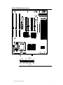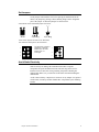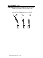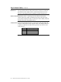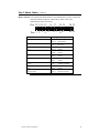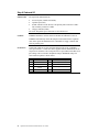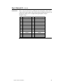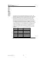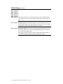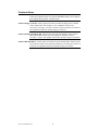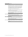
1
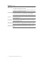
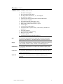
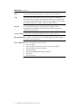
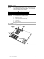
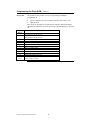
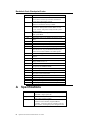
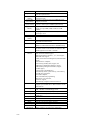
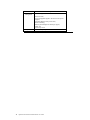
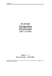
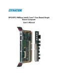
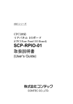
Apollo III PCI Pentium
ISA Motherboard
User's Guide
MAN-752
12/6/96
© Copyright 1996 American Megatrends, Inc.
All rights reserved.
American Megatrends, Inc.
6145F Northbelt Parkway
Norcross, GA 30071
This publication contains proprietary information which is protected by copyright. No part of this publication may be reproduced, transcribed,
stored in a retrieval system, translated into any language or computer language, or transmitted in any form whatsoever without the prior written
consent of the publisher, American Megatrends, Inc.
Limited Warranty
Buyer agrees if this product proves to be defective, that American Megatrends, Inc. is only obligated to replace or refund the purchase price of
this product at American Megatrends’ discretion according to the terms and conditions on the motherboard warranty card. American Megatrends
shall not be liable in tort or contract for any loss or damage, direct, incidental or consequential. Please see the Warranty Registration Card
shipped with this product for full warranty details.
Limitations of Liability
In no event shall American Megatrends be held liable for any loss, expenses, or damages of any kind whatsoever, whether direct, indirect,
incidental, or consequential, arising from the design or use of this product or the support materials provided with the product.
Trademarks
Intel and Pentium are registered trademarks of Intel Corporation.
MS-DOS, Microsoft Word, and Microsoft are registered trademarks of Microsoft Corporation.
SMC is a registered trademark of Standard Microsystems Corporation.
IBM, AT, VGA, PS/2, OS/2, and EGA are registered trademarks of International Business Machines Corporation. XT and CGA are trademarks
of International Business Machines Corporation.
Fujitsu is a registered trademark of Fujitsu America, Inc.
Motorola is a registered trademark of Motorola Corporation.
Hitachi is a registered trademark of Hitachi America, Ltd.
PNY is a registered trademark of PNY Corporation.
Oki is a registered trademark of Oki America, Inc.
NEC is a registered trademark of NEC Corporation.
Samsung is a registered trademark of Samsung Electronics Corporation.
Siemens is a trademark of Siemens Corporation.
Mitsubishi is a registered trademark of Mitsubishi Electronics of America.
Micron is a registered trademark of Micron Corporation.
SCO, UnixWare, and Unix are registered trademarks of The Santa Cruz Operation, Inc.
Toshiba is a registered trademark of Kabushiki Kaisha Toshiba.
VESA is a trademark of the Video Electronics Standards Association.
All other brand and product names are trademarks or registered trademarks of their respective companies.
Revision History
7/28/96
12/6/96
ii
Initial release.
Updated manual for new version of BIOS.
Apollo III PCI Pentium ISA Motherboard User’s Guide
Preface
To the OEM
Thank you for purchasing the high performance American Megatrends
Apollo III PCI Pentium ISA motherboard. This product is a state of the art
motherboard that includes the famous AMIBIOS. It is assumed that you have
also licensed the rights to use the American Megatrends documentation for
the American Megatrends Apollo III motherboard
This manual was written for the OEM to assist in the proper installation and
operation of this motherboard. This manual describes the specifications and
features of the Apollo III motherboard. It explains how to assemble a system
based on the Apollo III motherboard and how to use the AMIBIOS that is
specifically designed for this motherboard.
This manual is not meant to be read by the computer owner who purchases a
computer with this motherboard. It is assumed that you, the computer
manufacturer, will use this manual as a sourcebook of information, and that
parts of this manual will be included in the computer owner's manual.
Preface
iii
Packing List
You should have received the following:
•
•
•
•
•
•
an Apollo III Pentium PCI ISA motherboard,
an optional USB cable and mounting bracket,
two serial cables,
one parallel cable,
a Warranty Card, and
the American Megatrends Apollo III Pentium ISA Motherboard User's
Guide.
Static Electricity
The Apollo III motherboard can easily be damaged by static electricity. Make
sure you take appropriate precautions against static electric discharge:
•
•
•
Batteries
wear a properly-grounded wristband while handling the Apollo III
motherboard or any other electrical component,
touch a grounded anti-static surface or a grounded metal fixture before
handling the Apollo III motherboard,
handle system components by the mounting bracket, if possible.
Make sure you dispose of used batteries according to the battery
manufacturer’s instructions. Improper use of batteries may cause an
explosion. Make sure you follow the battery manufacturer’s instructions about
using the battery.
Replace used batteries with the same type of battery or an equivalent
recommended by the battery manufacturer.
Preface
iv
1
Hardware Installation
Overview
The American Megatrends Apollo III PCI Pentium ISA motherboard includes
the following features.
CPU
The motherboard supports an Intel® Pentium™ 75, 90, 100, 120, 133, 150,
166, 180, 200 MHz or higher speed CPU operating at Standard, VR, or VRE
voltages. The CPU speed and voltage are set via jumpers.
Upgrade CPU
You can install an Intel P54C series, P54CT, or P55C CPU.
Chipset
The Apollo III PCI Pentium ISA motherboard uses an Intel 82430HX,
including CPU interface controller, advanced cache controller, integrated
DRAM controller, synchronous ISA bus controller, PCI local bus interface,
and integrated power management unit.
Expansion slots The motherboard includes three 16-bit ISA expansion slots and four 32-bit
PCI expansion slots. The PCI local bus throughput can be up to 132
megabytes per second.
L1 Internal Cache The Intel Pentium on the motherboard has an 8 KB data cache and an 8
KB instruction cache.
L2 Secondary Cache The motherboard has either 256 KB or 512 KB of synchronous
PBSRAM, direct-mapped, write-back. L2 secondary cache memory.
Cont’d
Chapter 1 Hardware Installation
1
Overview, Continued
DRAM Cached If 256 KB of L2 secondary cache memory is installed on the motherboard, up
to 128 MB of system memory can be cached.
If 512 KB of L2 secondary cache memory is installed on the motherboard, up
to 256 MB of system memory can be cached.
System Memory The motherboard supports up to 256 MB of system memory mounted on the
motherboard in two banks of 72-pin 4 MB, 8 MB, or 16 MB SIMMs.
Use Fast Page Mode or Extended Data Out (EDO) SIMMs operating at 60 ns.
Fast ATA
The motherboard supports the Fast ATA specification using PIO mode 4 and
multiword DMA mode 2.
System BIOS
This motherboard has a 128 KB AMIBIOS system BIOS on a Flash ROM
with built-in WINBIOS Setup.
BIOS Shadowing The system BIOS is always copied from ROM to RAM for faster execution.
The end user can shadow 16 KB ROM segments from C0000h – DCFFFh.
Motherboard Size The Apollo III Pentium PCI ISA motherboard is 10 inches by 8.625
inches.
Cont’d
2
Apollo III PCI Pentium ISA Motherboard User’s Guide
Overview, Continued
AMIBIOS Features AMIBIOS features include:
•
•
•
•
•
•
•
•
•
•
•
•
•
•
•
•
•
IDE block mode support,
IDE 32-bit data transfer support,
IDE Programmed I/O mode 0, 1, 2, 3, and 4 support,
IDE LBA mode support,
APM (Advanced Power Management) and Flash BIOS hooks,
EPA Green PC-compliant,
PCI and Plug and Play (PnP) support, and
DIM (Device Initialization Manager) support,
DMI (Desktop Management Interface) support,
ATAPI support,
can boot from a CD-ROM drive,
automatically detects system memory, cache memory, and IDE drive
parameters,
Intel NSP-compliant,
Fast ATA IDE mode programming,
Boot sector virus protection,
instant-on support,
automatically configures PnP and PCI devices.
IDE
The Apollo III motherboard has two 40-pin IDE connectors onboard that
support up to four IDE drives. The IDE controller is on the PCI local bus.
Floppy
The Apollo III motherboard has an onboard floppy controller that supports up
to two 360 KB, 720 KB, 1.2 MB, 1.44 MB, or 2.88 MB floppy drives.
Parallel Port
The Apollo III motherboard has an onboard ECP and EPP-capable parallel
port connector.
Serial Ports
The Apollo III motherboard has two onboard serial port connectors and two
16550 UART serial ports.
Keyboard
The Apollo III motherboard Includes a standard miniDIN keyboard
connector.
Cont’d
Chapter 1 Hardware Installation
3
Overview, Continued
Mouse
The Apollo III motherboard includes a 5-pin berg mouse connector.
USB
The Apollo III motherboard has two 4-pin USB connectors. USB allows
future generations of USB-compliant peripheral devices to be automatically
detected and configured through a single port. The AMIBIOS on the Apollo
III motherboard provides complete USB system BIOS support.
Infrared
A 10-pin infrared connector is provided on the motherboard. The
motherboard and AMIBIOS comply with the IrDA SIR infrared device
standards and specifications.
Power Connectors The Apollo III motherboard has three power supply connectors.
RTC/CMOS RAM A real time clock and 128 bytes of CMOS RAM with a battery backup is
provided on the motherboard.
Power Management Power management services include:
•
•
•
•
•
•
•
Green PC LED,
power management signal to Green PC-aware power supplies,
automatic IDE and video power down,
monitor blanking,
SMI (System Management Interrupt) support,
APM, and
system stop clock.
Cont’d
4
Apollo III PCI Pentium ISA Motherboard User’s Guide
Overview, Continued
PCI Slots
The motherboard conforms to the PCI Version 2.1 specification. The PCI
slots are automatically configured by the AMIBIOS. The PCI slots operate
synchronously with the CPU clock, as follows:
CPU External Clock Frequency
66 MHz
60 MHz
50 MHz
Onboard I/O
PCI Expansion Slot Frequency
33 MHz
30 MHz
25 MHz
The Apollo III Pentium ISA motherboard includes:
•
•
•
•
•
•
•
•
two 40-pin IDE connectors on the PCI bus that support up to four IDE drives,
a 34-pin floppy drive connector,
two 10-pin serial port connectors (with 16550 UARTs),
a 26-pin parallel port connector with ECP and EPP support,
an infrared connectors,
two USB connectors,
a keyboard connector, and
a PS/2 mouse connector.
Apollo III Dimensions
Keyboard
Connector
0.85"
Power Connectors
2.0"
SIMM
Sockets
2.5"
Expansion
Slots
0.62"
CPU Heat Sink
1.75"
8.625"
10"
Heat Sink
1.5"
Chapter 1 Hardware Installation
5
Installation Steps
Step
1
2
3
4
5
6
7
8
9
Action
Unpack the motherboard.
Configure the CPU.
Select the CPU voltage.
Select the CPU speed.
Install the CPU.
Install memory.
Install system memory.
Install the motherboard.
Attach cables to connectors.
Connect the power supply.
Attach the keyboard cable.
Connect the mouse cable.
Attach cables.
Connect onboard I/O.
Connect the serial ports.
Connect the parallel port.
Connect floppy drive(s).
Connect the IDE drive(s).
Test and configure.
Warning
This motherboard contains sensitive electronic
components that can be easily damaged by static
electricity. Follow the instructions carefully to
ensure correct installation and to avoid static
damage.
6
Apollo III PCI Pentium ISA Motherboard User’s Guide
Apollo III Motherboard Layout
USB1
USB2
PS/2 Mouse Keyboard
RPW_CON
IR
Floppy
LPT1
COM1
COM2
PCI SLOT 1
PCI SLOT 2
PCI SLOT 3
PCI SLOT 4
EP3
EP2
EP1
Power Supply
AMIBIOS
CPS
IDE1
IDE2
CLK1
CLK2
Bank0
Bank1
VR1
VR2
FREQ2
FREQ1
M2
M1
M4
M3
Fan
M6
The connectors in this Block
Header are detailed below.
A Square Pad identifies Pin 1
in Jumpers and Connectors.
Speaker
PWR
LED
IDE
LED
Kbd
Lock
Chapter 1 Hardware Installation
Remote
Power
Switch
Turbo Susp.
LED Mode
Switch
M5
Tag RAM
Reset
Susp.
LED
7
Step 1 Unpack the Motherboard
Step
1
2
3
4
5
8
Action
Inspect the cardboard carton for obvious damage. If damaged,
call 770-246-8645. Leave the motherboard in its original
packing.
Perform all unpacking and installation procedures on a groundconnected anti-static mat. Wear an anti-static wristband
grounded at the same point as the anti-static mat. Or use a
sheet of conductive aluminum foil grounded through a 1
megohm resistor instead of the anti-static mat. Similarly, a
strip of conductive aluminum foil wrapped around the wrist
and grounded through a 1 megohm resistor serves the same
purpose as the wristband.
Inside the carton, the motherboard is packed in an anti-static
bag, and sandwiched between sheets of sponge. Remove the
sponge and the anti-static bag. Place the motherboard on a
grounded anti-static surface component side up. Save the
original packing material.
Inspect the motherboard for damage. Press down on all ICs
mounted in sockets to verify proper seating. Do not apply
power to the motherboard if it has been damaged.
If the motherboard is undamaged, it is ready to be installed.
Apollo III PCI Pentium ISA Motherboard User’s Guide
Set Jumpers
Set all jumpers and install the CPU before placing the motherboard in the
chassis. Set jumpers by placing a shunt (shorting bridge) on the designated
pins of the jumper. A shunt and jumpers are shown below:
3-dimensional view of motherboard jumpers and a shunt.
Shunt
3-pin Berg
2-pin Berg
In this manual, jumpers are shown in two -dimensions,
as if viewed from directly above, as shown below:
1
2
3
4
5
6
The placement of shunts is
indicated by a solid line
between pins, as shown
between Pins 1-2
to the right:
1
2
3
4
5
6
Avoid Static Electricity
Static electricity can damage the motherboard and other computer
components. Keep the motherboard in the anti-static bag until it is to be
installed. Wear an anti-static wrist grounding strap before handling the
motherboard. Make sure you stand on an anti-static mat when handling the
motherboard.
Avoid contact with any component or connector on any adapter card, printed
circuit board, or memory module. Handle these components by the mounting
bracket.
Chapter 1 Hardware Installation
9
Step 2 Configure CPU
Important
Perform the following steps to configure the
motherboard before installing a CPU.
External and Internal CPU Clock CLK1, CLK2, FREQ1, and FREQ2 are 3-pin bergs that set
the CPU external and internal clock frequencies. FREQ1 and FREQ2 are next
to the CPU. CLK1 and CLK2 are towards the middle of the motherboard.
External
66 MHz
Internal
166 MHz
60 MHz
150 MHz
66 MHz
133 MHz
60 MHz
120 MHz
66 MHz
100 MHz
60 MHz
90 MHz
50 MHz
75 MHz
60 MHz
180 MHz
66 MHz
200 MHz
CLK1
Short Pins
1-2
Short Pins
2-3
Short Pins
1-2
Short Pins
2-3
Short Pins
1-2
Short Pins
2-3
Short Pins
2-3
Short Pins
2-3
Short Pins
1-2
CLK2
Short Pins
2-3
Short Pins
1-2
Short Pins
2-3
Short Pins
1-2
Short Pins
2-3
Short Pins
1-2
Short Pins
2-3
Short Pins
1-2
Short Pins
2-3
FREQ1
Short Pins
2-3
Short Pins
2-3
Short Pins
2-3
Short Pins
2-3
Short Pins
1-2
Short Pins
1-2
Short Pins
1-2
Short Pins
1-2
Short Pins
1-2
FREQ2
Short Pins
2-3
Short Pins
2-3
Short Pins
1-2
Short Pins
1-2
Short Pins
1-2
Short Pins
1-2
Short Pins
1-2
Short Pins
2-3
Short Pins
2-3
Important
Please contact American Megatrends technical
support at 770-246-8645 if you need to support a
CPU running at a higher speed.
Cont’d
10
Apollo III PCI Pentium ISA Motherboard User’s Guide
Step 2 Configure CPU, Continued
JVR Set CPU Voltage Install Intel Pentium CPUs that adhere to either the standard or VRE
voltage specifications. VR1 and VR2 are 6-pin bergs that set CPU voltage.
VR1 is near the top of the CPU socket. VR2 is next to the CPU, near the edge
of the motherboard.
Standard and VRE Voltage This is the factory setting.
3.49V Standard and VRE
for Intel P54C CPUs
Pins 7
5
Pins 8
6
3
1
Pins 7
4
2
Pins 8
5
6
VR1
3
1
4
2
VR2
Standard Voltage
3.3V Standard
for Intel P54C CPUs
Pins 7
5
Pins 8
6
3
1
Pins 7
5
4
2
Pins 8
6
VR1
3
1
4
2
VR2
Mixed Voltage
2.8V and 3.3V
for Intel P55C CPUs
Pins 7
Pins 8
5
6
3
1
Pins 7
5
4
2
Pins 8
6
VR1
3
1
4
2
VR2
Cont’d
Chapter 1 Hardware Installation
11
Step 2 Configure CPU, Continued
Important
If you are not sure about the voltage specification
for the CPU that will be installed in this
motherboard, please call Intel and make sure that
you set the voltage jumpers correctly. Selecting the
wrong voltage may damage the CPU.
Install CPU
Install the CPU in the ZIF (zero insertion force) socket by performing the
following steps. The CPU socket is near one edge of the motherboard.
Warning
Improper CPU installation can damage the CPU
and the motherboard. You must follow the
procedures in this section exactly as documented.
Make sure you wear an antistatic wristband while
installing the CPU.
Step
1
12
Action
Lift the lever on the ZIF socket. The empty CPU socket
looks like this.
Apollo III PCI Pentium ISA Motherboard User’s Guide
Step
2
Action
Check for bent pins on the CPU. Gently straighten any bent
pins with pliers. Place the CPU in the middle of the socket,
as shown below. Make sure that pin 1 of the CPU is aligned
with pin 1 of the socket. Make sure you are properly
grounded while handling the CPU.
3
Complete installation by lifting the ZIF lever to the other
side of the socket, as shown below.
Chapter 1 Hardware Installation
13
Step 3 Install Memory
System Memory The motherboard has four 32-bit SIMM – Single Inline Memory Module)
sockets. You can use Fast Page Mode or EDO (Extended Data Out) SIMMs.
Memory must be populated one bank at a time. Each bank has two sockets.
Each bank must be populated with the same type of SIMM. If a 1 MB SIMM
is installed in the first socket in Bank0, then the same type of 1 MB SIMM
must be installed in the second Bank0 SIMM socket. Each socket can hold
one 72-pin SIMM. You can use:
•
•
•
1 MB x 36,
4 MB x 36,
8 MB x 36, or
16 MB x 36 SIMMs.
•
The motherboard supports banks of fast page mode and EDO (Extended Data
Out) memory together operating at 60 ns (RAS access time).
Memory Display
System memory is reported by AMIBIOS as it boots and again when
the AMIBIOS System Configuration Screen is displayed just before the
operating system boots. The memory displayed by AMIBIOS on the System
Configuration Screen is 384 KB less than the total memory installed.
SIMM Part Numbers
Type
4 MB x 36
“
“
“
“
8 MB x 36
“
“
Manufacturer
Micron
Mitsubishi
Motorola
PNY
Samsung
Motorola
PNY
Samsung
Part Number
MT12D436M-6
MH4M36SAJ-6
MCM36400S-60
P364000-60
KMM5364100-6
MCM36800S-60
P368000-60
KMM5368100-6
Cont’d
14
Apollo III PCI Pentium ISA Motherboard User’s Guide
Step 3 Install Memory, Continued
DRAM Configurations Valid memory configurations include:
Total RAM
8 MB
16 MB
24 MB
32 MB
40 MB
48 MB
64 MB
64 MB
72 MB
80 MB
96 MB
128 MB
136 MB
144 MB
160 MB
192 MB
256 MB
Bank0
4 MB
8 MB
8 MB
8 MB
16 MB
16 MB
16 MB
32 MB
32 MB
32 MB
32 MB
32 MB
64 MB
64 MB
64 MB
64 MB
64 MB
Bank0
4 MB
8 MB
8 MB
8 MB
16 MB
16 MB
16 MB
32 MB
32 MB
32 MB
32 MB
32 MB
64 MB
64 MB
64 MB
64 MB
64 MB
Bank1
None
None
4 MB
8 MB
4 MB
8 MB
16 MB
None
4 MB
8 MB
16 MB
32 MB
4 MB
8 MB
16 MB
32 MB
64 MB
Bank1
None
None
4 MB
8 MB
4 MB
8 MB
16 MB
None
4 MB
8 MB
16 MB
32 MB
4 MB
8 MB
16 MB
32 MB
64 MB
Cont’d
Chapter 1 Hardware Installation
15
Step 3 Install Memory, Continued
Installing SIMMs The motherboard has four x 36 SIMM sockets. These sockets can be filled
with either 1 MB x 36, 4 MB x 36, 8 MB x 36, or 16 MB x 36 SIMMs.
Place the motherboard on an anti-static mat. With the component side of the
SIMM facing you, firmly push the SIMM into the socket at an angle, then
push it up. When properly inserted, the SIMM clicks into place as the
latching pins engage. The SIMM installation process is shown below:
Cont’d
16
Apollo III PCI Pentium ISA Motherboard User’s Guide
Step 3 Install Memory, Continued
Configure Cache Memory The motherboard supports 256 KB or 512 KB of L2 3V Pipeline
Burst SRAM secondary cache memory. Either 256 KB or 512 KB of Pipeline
Burst Mode Static RAM L2 secondary cache memory is mounted on the
motherboard. You cannot upgrade L2 secondary cache memory.
L2 Cache Size
256 KB
512 KB
Cache DIP Type
32 KB x 32 (M2 and M4)
32 KB x 32 (M1, M2, M3,
and M4)
Tag RAM Type
8 KB x 8 (M5)
16 KB x 8 (M5, M6)
Flash ROM Type You must specify the type of flash EPROM installed on the motherboard, as
follows. EP1, EP2, and EP3 are next to the BIOS ROM between the ISA and
PCI expansion slots.
Flash ROM Type
Intel 28F010
Intel 28F001BX-T
SST 29EE010
(factory setting)
AMD28F020
SST29EE020
Chapter 1 Hardware Installation
EP1
Short Pins 1-2
Short Pins 1-2
Short Pins 2-3
EP2
Short Pins 2-3
Short Pins 1-2
Short Pins 2-3
EP3
OPEN
OPEN
OPEN
OPEN
OPEN
Short Pins 1-2
Short Pins 2-3
Short Pins 2-3
Short Pins 2-3
17
Step 4 Install the Motherboard
The motherboard mounting hole pattern is the same as the mounting hole
pattern on the standard baby AT motherboard. Standoffs and mounting
screws are not supplied with the motherboard. The chassis manufacturer
should supply these parts.
Step
1
2
3
4
5
Action
Place the chassis on an anti-static mat. Connect the chassis to
ground to avoid static damage during installation. Connect an
alligator clip with a wire lead to any unpainted part of the chassis.
Ground the other end of the lead at the same point as the mat and
the wristband.
Rotate the chassis so the front is to the right, and the rear is to the
left. The side facing you is where the motherboard is mounted.
The power supply is mounted at the far end of the chassis.
Hold the motherboard, component-side up, with the edge with the
SIMM sockets toward you and the edge with the power supply
connector away from you. The keyboard, mouse, and video
connectors should be to the left.
Carefully slide the motherboard into the chassis. Make certain the
edge connectors fit the ports in the rear of the chassis. The
motherboard should rest level with the chassis.
Place the mounting screws in the holes provided and tighten them.
If necessary, shift the motherboard slightly to align the mounting
holes on the motherboard with the holes on the chassis. See the
drawing on the next screen.
Warning
If using metallic screws, make sure you use them
only in the plated mounting holes.
If using metallic screws, make sure the head of
the screw fits completely inside the plated
mounting holes.
See the graphic on the following screen.
Cont’d
18
Apollo III PCI Pentium ISA Motherboard User’s Guide
Step 4 Install Motherboard, Continued
Chapter 1 Hardware Installation
19
Step 5 Attach Cables
Connectors
The Apollo III motherboard includes many connectors. Connection
instructions, illustrations of connectors, and pinouts are listed below. A list of
all connectors described in this section follows:
Connector
CPS Clear password
Power supply connector
Keyboard connector
Mouse connector
CPU Fan
Infrared
Remote Power connector
USB connectors
Speaker
IDE LED
Remote Power Switch
Hardware Reset Switch
Power LED (lit when power is on)
Keyboard Lock
Turbo LED (lit when high speed is active)
Suspend Mode Switch
Suspend LED (lit when system in suspend
mode)
Serial Port
Parallel port
Floppy drive connector
IDE drive connectors
Cont’d
20
Apollo III PCI Pentium ISA Motherboard User’s Guide
Step 5 Attach Cables, Continued
Cable Connector Ends When connecting chassis connectors to the motherboard, make sure
to connect the correct connector end. Most connector wires are color-coded.
Match the color of the wires leaving the switch or LED to the same pin on the
connector end. There may be more than one connector with the same colorcoded wires. If so, follow the wire to the switch or LED. Pin 1 is indicated for
all motherboard components by a white line. Pin 1 is always nearest to the
white line.
3 2 1
CPS Clear Password If you forget the computer password, the only course of action is to erase
the system configuration information stored in the NVRAM (Non-Volatile
Random Access Memory). The computer password is stored in the system
configuration data. Short the CPS pins together for two seconds. CPS is
located near the bottom of PCI Slot4. All system memory will be erased. You
must now turn the computer power on and run WINBIOS Setup to reset all
system configuration information. Make sure that CPS remains OPEN unless
you have to erase a forgotten password.
Cont’d
Chapter 1 Hardware Installation
21
Step 5 Attach Cables, Continued
Connect Power Supply The power supply should match the physical configuration of the
chassis. Make sure that the power switch is Off before assembly.
Before attaching all components, make sure that the proper voltage has been
selected. Power supplies often can run on a wide range of voltages and must
be set (usually via a switch) to the proper range. Use at least a 200 watt power
supply, which should have built-in filters to suppress radiated emissions.
Power Cables
Attach the power supply cables to the power connector on the motherboard.
AT-compatible power supplies have one twelve pin connector, as shown
below.
Pin 1
NGE
OR A
RED OW
YEL L
E
BLU
CK
A
L
B
CK
BLA
K
BLAC K
C
BLA K
BLAC
RED
RED
RED
Pin 12
Cont’d
22
Apollo III PCI Pentium ISA Motherboard User’s Guide
Step 5 Attach Cables, Continued
Connector Keys The keys on the connector must be cut to fit on some power supplies, as
shown below.
Power Connector Pinout
Pin
Description
1
Power Good (Orange wire) (Not used)
2
VCC (Red wire)
3
+12 Volts (Yellow wire)
4
-12 Volts (Blue wire)
5
Ground (Black wire)
6
Ground (Black wire)
7
Ground (Black wire)
8
Ground (Black wire)
9
-5 Volts (White wire)
10
VCC (Red wire)
11
VCC (Red wire)
12
VCC (Red wire)
Keyboard Cable The keyboard attaches via a PS/2 keyboard connector, labeled KB_CONN.
Pin
Assignments
1
Keyboard data
2
N/C
3
Ground
4
VCC
5
Keyboard clock
6
N/C
Cont’d
Chapter 1 Hardware Installation
23
Step 5 Attach Cables, Continued
Mouse Cable
Attach the mouse connector cable supplied by American Megatrends to the
five-pin mouse berg connector on the motherboard (labeled MS_COM), as
shown below. Attach the standard 9-pin mouse connector at the other end of
the mouse cable to the mouse connector port on the computer case. Incorrect
mouse installation can cause the system to hang.
Error! Not a valid filename.
Pin
1
2
3
4
5
Description
Mouse Clock
N/C
N/C
Mouse Data
Ground
Cont’d
24
Apollo III PCI Pentium ISA Motherboard User’s Guide
Step 5 Attach Cables, Continued
When connecting chassis connectors to the motherboard, make sure to
connect the correct connector end. Most connector wires are color-coded.
Match the color of the wires leaving the switch or LED to the same pin on the
connector end. There may be more than one connector with the same colorcoded wires. If so, follow the wire to the switch or LED. Pin 1 is always
indicated on the motherboard, as shown below:
CPU Fan
A three-pin berg labeled FAN attaches to the CPU fan. The FAN connector is
next to the CPU socket.
Pin
1
2
3
Description
Ground
+12V
Ground
Cont’d
Chapter 1 Hardware Installation
25
Step 5 Attach Cables, Continued
IR Infrared
The 8-pin infrared connector (IR1) near PCI Slot 1 connects to an infrared
port mounted on the computer chassis. It allows data transmission to any
other device that supports the IrDA standards for infrared transmission.
Remote Control Power RPW_COM is a 2-pin berg next to the infrared connector that
connects to the power supply for enabling system power when the remote
power switch is turned on. Connect a 2-wire power cable to RPW_COM and
attach the other end to the peripheral device.
USB Connectors The Apollo III motherboard has two 4-pin headers (USB1 and USB2) that
attach to a USB connector on the computer chassis. The USB port allows you
to attach to a USB hub. The USB connector pinouts are the same for both
USB connectors:
Pin
1
2
3
4
Signal Description
VCC (Fused 5V)
- Data
+ Data
Ground
Cont’d
26
Apollo III PCI Pentium ISA Motherboard User’s Guide
Step 5 Attach Cables, Continued
Block Connector The Apollo III motherboard has a 22-pin header that is used to connect the
following offboard connectors. The header is on the corner of the
motherboard near the CPU socket.
Pins 12 13 14 15
16 17
Pins 1 2 3 4 5
Connector
Speaker
IDE LED
Remote Power Switch (Power when
low).
Hardware Reset Switch
Power LED (lit when power is on)
Keyboard Lock
Turbo LED (lit when low speed is
active)
Suspend Mode Switch (Suspend when
Low)
Suspend LED (lit when system in
suspend mode)
Chapter 1 Hardware Installation
6 7
18 19
20 21
89
10 11
Signal Descriptions
Pin 12 VCC
Pin 15 Speaker Data
Pin 16 LED Power
Pin 17 IDE Active
Pin 18 Remote Power
Pin 19 Ground
Pin 20 Hard Reset
Pin 21 Ground
Pin 1
+Power
Pin 2
Ground
Pin 4
Keyboard Lock
Pin 5
Ground
Pin 6
TURBO_LIT
Pin 7
TURBO_LEDPWR
Pin 8
Suspend In Switch
Pin 9
Ground
Pin 10 Suspend Out LED+
Pin 11 Suspend Out LED-
27
Step 6 Onboard I/O
Onboard I/O
The Apollo III motherboard has:
•
•
•
two serial ports (COM1 and COM2),
a parallel port (LPT),
an IDE controller on the PCI bus. The primary IDE connector is IDE1.
The secondary connector is IDE2.
a floppy controller (FDD).
•
The serial and parallel port connectors are described below.
Conflicts
AMIBIOS minimizes conflicts between onboard and offboard I/O devices.
AMIBIOS automatically checks the adapter cards installed in the expansion
slots on the Apollo III motherboard for a hard disk or floppy controller and
serial or parallel ports.
Serial Ports
COM1 and COM2 are 10-pin connectors that provide an AT-compatible
serial port interface. Connect the cables supplied with the motherboard to the
10-pin serial connectors. The serial port base I/O port address and other serial
port settings can be selected in Peripheral Setup in WINBIOS Setup. The
serial connector pinout is shown below.
Pin
1
2
3
4
5
Description
Carrier Detect
Receive Data
Transmit Data
Data Terminal
Ready
Ground
Pin
6
7
8
9
10
Signal Description
Data Set Ready
Request to Send
Clear to Send
Ring Indicator
CUT PIN
Cont’d
28
Apollo III PCI Pentium ISA Motherboard User’s Guide
Step 6 Onboard I/O, Continued
Parallel Port
LPT is a 26-pin connector for a parallel port. The LPT pinout is shown below.
Connect the 26-pin to DB25 cable provided with the motherboard to LPT. All
parallel port settings can be configured through Peripheral Setup in
WINBIOS Setup.
Pin
Signal Description
Pin
1
STROBE#
2
PD0
3
5
PD1
PD3
4
6
PD2
PD4
7
9
11
PD5
PD7
BUSY
8
10
12
PD6
ACK#
PE
13
15
17
19
21
23
25
SLCT
ERROR#
SLCTIN#
Ground
Ground
Ground
Ground
14
16
18
20
22
24
26
AUTOFD#
INIT#
Ground
Ground
Ground
Ground
Ground
Chapter 1 Hardware Installation
Signal Description
29
Step 7 Attach Floppy Drive
FDD is a 34-pin dual-inline berg. Connect the cable from the floppy drive to
FDD, as shown below. The onboard floppy controller cannot be used if a hard
disk card with a floppy controller is installed. Choose Standard Setup and
Peripheral Setup to configure the floppy controller.
The motherboard supports up to two 720 KB, 1.44 MB, or 2.88 MB 3½"
drives and 360 KB and 1.2 MB 5¼" drives. The connecting cable is a 34-pin
ribbon connector with two 34-pin edge connectors for attaching the floppy
disk drives. There is a small twist in the cable between the floppy connectors.
The last (end) connector should be connected to floppy drive A:.
Cont’d
30
Apollo III PCI Pentium ISA Motherboard User’s Guide
Step 7 Attach Floppy Drive, Continued
Floppy Connector Pinout
Pin
Use
Pin
Use
1
GND
2
DENSE1
3
GND
4
N/C
5
7
GND
GND
6
8
DRATE0
-INDEX
9
GND
10
-MOTOR0
11
13
GND
GND
12
14
-FDSEL1
-FDSEL0
15
17
GND
GND
16
18
-MOTOR1
DIR
19
GND
20
-
21
23
25
27
29
31
33
GND
GND
GND
GND
GND
GND
GND
22
24
26
28
30
32
34
-WDATA
-WGATE
-TRK0
-WRPROT
-RDATA
HDSEL
DSKCHNG
Twist in Floppy Cable
Floppy B to A
Floppy B to A
Floppy B to A
Floppy B to A
10 to 16
12 to 14
14 to 12
16 to 10
11 to 15
13 to 13
15 to 11
Chapter 1 Hardware Installation
31
Step 8 Attach IDE Drive
IDE Drives
Attach the IDE drives in the following manner. Choose Peripheral Setup in
WINBIOS Setup to enable the onboard IDE controller.
Cont’d
32
Apollo III PCI Pentium ISA Motherboard User’s Guide
Step 8 Attach IDE Drive, Continued
Attach IDE Cable IDE1 is the primary IDE (Integrated Drive Electronics) hard disk drive
connector. Both the primary master and the primary slave IDE drives must be
connected by cable to IDE1, as shown below.
IDE1 is a 40-pin dual-inline berg that connects an IDE drive to the primary
onboard IDE connector. This motherboard supports IDE Modes 0, 1, 2, 3, and
4, IDE prefetch, LBA (Logical Block Address) mode, high capacity drives
(over 528 MB), 32-bit data transfer, and fast IDE transfer. These IDE features
are configured in Peripheral Setup in the WINBIOS Setup utility. Disable the
onboard IDE interface in Peripheral Setup to use an ISA ESDI, RLL, MFM,
or SCSI hard disk drive controller.
Cont’d
Chapter 1 Hardware Installation
33
Step 8 Attach IDE Drive, Continued
IDE1 Pinout
The IDE1 pinout is:
Pin
1
3
5
7
9
11
13
15
17
19
21
23
25
27
29
31
33
35
37
39
Use
-RESET
DATA7
DATA6
DATA5
DATA4
DATA3
DATA2
DATA1
DATA0
GND
N/C
-IOW
-IOR
IDERDY
N/C
INT14
HA1
HA0
-CS0
-IDEACT
Pin
2
4
6
8
10
12
14
16
18
20
22
24
26
28
30
32
34
36
38
40
Use
GND
DATA8
DATA9
DATA10
DATA11
DATA12
DATA13
DATA14
DATA15
KEY (N/C)
GND
GND
GND
ALE
GND
-IOCS16
N/C
HA2
-CS1
GND
IDE2 Secondary IDE Controller IDE2, the secondary IDE connector, is a 40-pin dual-inline
berg that connects the secondary primary and slave IDE drives to the
secondary onboard IDE controller.
Attach the secondary master and slave IDE drives to IDE2 via a standard 40pin IDE cable.
Cont’d
34
Apollo III PCI Pentium ISA Motherboard User’s Guide
Step 8 Attach IDE Drive, Continued
IDE2 Pinout
The IDE2 pinout is:
Pin
1
3
5
7
9
11
13
15
17
19
21
23
25
27
29
31
33
35
37
39
Chapter 1 Hardware Installation
Use
-RESET
DATA7
DATA6
DATA5
DATA4
DATA3
DATA2
DATA1
DATA0
GND
N/C
-IOW
-IOR
IDERDY
N/C
INT15
HA1
HA0
-CS2
N/C
Pin
2
4
6
8
10
12
14
16
18
20
22
24
26
28
30
32
34
36
38
40
Use
GND
DATA8
DATA9
DATA10
DATA11
DATA12
DATA13
DATA14
DATA15
KEY (N/C)
GND
GND
GND
ALE
GND
-IOCS16
N/C
HA2
-CS3
GND
35
Step 9 Test and Configure
Review the following points before powering up:
•
•
•
•
•
•
make sure that all adapter cards are seated properly,
make sure all connectors are properly installed,
make sure the CPU is seated properly,
make sure there are no screws or other foreign material on the
motherboard,
plug the system into a surge-protected power strip, and
make sure blank back panels are installed on the back of the chassis to
minimize RF emissions.
Start the Test
Plug everything in and turn on the switch. If there are any signs of a problem,
turn off the unit immediately. Reinstall the connectors. Call Technical
Support if there are problems.
BIOS Errors
If the system operates normally, a display should appear on the monitor. The
BIOS Power On Self Test (POST) should execute.
If POST does not run successfully, it will beep or display error messages.
Beeps indicate a serious problem with the system configuration or hardware.
The Beep Code indicates the problem. AMIBIOS Beep Codes are defined in
the AMIBIOS Technical Reference. Make sure the affected part is properly
seated and connected. An error message is displayed if the error is less
serious. Recheck the system configuration or the connections.
Configure the System Run WINBIOS Setup. You must enter the requested information and
save the configuration data in CMOS RAM. The system will then reset, run
POST, and boot the operating system. See the following chapter for
information about configuring the computer.
36
Apollo III PCI Pentium ISA Motherboard User’s Guide
2
WINBIOS Setup
In ISA and EISA computers, the system parameters (such as amount of
memory, type of disk drives and video displays, and many other elements) are
stored in CMOS RAM. Unlike the DRAM (dynamic random access memory)
that is used for standard system memory, CMOS RAM requires very little
power. When the computer is turned off, a back-up battery provides power to
CMOS RAM, which retains the system parameters. Every time the computer
is powered-on, the computer is configured with the values stored in CMOS
RAM by the system BIOS, which gains control when the computer is powered
on.
The system parameters are configured by a system BIOS Setup utility.
Historically, BIOS Setup utilities have been character-based, required
keyboard input, and have had user interfaces that were not very intuitive.
Graphical Interface American Megatrends has a new type of system BIOS Setup utility.
WINBIOS Setup has a graphical user interface the end user can access using
a mouse. The WINBIOS Setup code is so compact that it can reside on the
same ROM as the system BIOS. The system configuration parameters are set
by WINBIOS Setup.
Since WINBIOS Setup resides in the ROM BIOS, it is available each time the
computer is turned on.
Starting WINBIOS Setup
As POST executes, the following appears:
Hit <DEL> if you want to run SETUP
Press <Del> to run WINBIOS Setup.
Chapter 2 WINBIOS Setup
37
Using a Mouse with WINBIOS Setup
WINBIOS Setup has a built-in mouse driver and can be accessed by either a
serial mouse or PS/2-style mouse. WINBIOS Setup supports MicrosoftCompatible serial mice and all PS/2-type mice.
The mouse click functions are: single click to change or select both global
and current fields and double click to perform an operation in the selected
field.
Using the Keyboard with WINBIOS Setup
WINBIOS has a built-in keyboard driver that uses simple keystroke
combinations:
Keystroke
<Tab>
<→, ←, ↑, ↓
<Enter>
+
–
<Esc>
<PgUp>
<PgDn>
<Home>
<End>
<Ctrl><Alt><+>
<Ctrl><Alt><->
38
Action
Change or select a global field.
Change or select the current field.
Perform an operation in the current field.
Increment a value.
Decrement a value.
Abort any window function.
Return to the previous screen.
Advance to the next screen.
Returns to the beginning of the text.
Advance to the end of the text.
Change to high speed.
Change to low speed.
Apollo III PCI Pentium ISA Motherboard User’s Guide
WINBIOS Setup Menu
The WINBIOS Setup main menu is organized into four sections. Each of
these sections corresponds to a section in this chapter.
Each section contains several icons. Clicking on each icon activates a specific
AMIBIOS function. The WINBIOS Setup main windows and related
functions are described below.
Main Windows The WINBIOS Setup main windows are:
•
•
•
•
Chapter 2 WINBIOS Setup
Setup, described in Section 1, has icons that permit you to set system
configuration options such as date, time, hard disk type, floppy type, and
many others,
Security, described in Section 2, has three icons that control AMIBIOS
security features, and
Utilities, described in Section 3, sets the screen color and allows
language changes,
Default, described in Section 4, this section has three icons that permit
you to select a group of settings for all WINBIOS Setup options.
39
Section 1 Setup
Standard Setup
Standard Setup options are displayed by choosing the Standard icon from the
WINBIOS Setup main menu. All Standard Setup options are described in this
section.
Date/Time
Select the Standard option. Select the Date and Time icon. The current values
for each category are displayed. Enter new values through the keyboard.
Floppy Drive A: and B: Move the cursor to these fields via ↑ and ↓ and select the floppy
type. The settings are 360 KB 5¼ inch, 1.2 MB 5¼ inch, 720 KB 3½ inch,
1.44 MB 3½ inch, or 2.88 MB 3½ inch.
40
Apollo III PCI Pentium ISA Motherboard User’s Guide
Standard Setup, Continued
Primary Master, Primary Slave, Secondary Master, Secondary Slave Select one of these
hard disk drive icons to configure the hard disk drive named in the option.
Select Auto from the drive parameters screen to let AMIBIOS automatically
configure the drive. A screen with a list of drive parameters appears. Click on
OK to configure the drive.
Drive Type
SCSI
IDE
How to Configure
Select Type. Select Not Installed in the drive parameter
screen. The SCSI drivers provided by the SCSI drive or
SCSI host adapter manufacturer should allow you to
configure the SCSI drive.
Select Type. Select Auto to let AMIBIOS determine the
parameters. Click on OK when AMIBIOS displays the drive
parameters.
Select LBA/Large Mode. Select On if the drive has a
capacity greater than 540 MB.
Select Block Mode. Select On to allow block mode data
transfers.
Select 32-Bit Transfer. Select On to allow 32-bit data
transfers.
CD-ROM
Standard
MFM Drive
NonStandard
MFM Drive
Select the PIO Mode. It is best to select Auto to allow
AMIBIOS to determine the PIO mode. If you select a PIO
mode that is not supported by the IDE drive, the drive will
not work properly. If you are absolutely certain that you
know the drive’s PIO mode, select PIO mode 0 - 5, as
appropriate.
Select Type. Select CDROM. Click on OK when AMIBIOS
displays the drive parameters.
Select Type. You must know the drive parameters. Select
the drive type that exactly matches your drive’s parameters.
Select Type. If the drive parameters do not match the drive
parameters listed for drive types 1 - 46, select User and
enter the correct hard disk drive parameters.
Cont’d
Chapter 2 WINBIOS Setup
41
Standard Setup, Continued
Entering Drive Parameters You can also enter the hard disk drive parameters. The drive
parameters are:
Parameter
Type
Cylinders
Heads
Write
Precompensation
Landing Zone
Sectors
Capacity
Description
The number for a drive with certain identification
parameters.
The number of cylinders in the disk drive.
The number of heads.
The actual physical size of a sector gets progressively
smaller as the track diameter diminishes. Yet each
sector must still hold 512 bytes. Write
precompensation circuitry on the hard disk
compensates for the physical difference in sector size
by boosting the write current for sectors on inner
tracks. This parameter is the track number on the disk
surface where write precompensation begins.
This number is the cylinder location where the heads
normally park when the system is shut down.
The number of sectors per track. MFM drives have 17
sectors per track. RLL drives have 26 sectors per
track. ESDI drives have 34 sectors per track. SCSI
and IDE drives have even more sectors per track.
The formatted capacity of the drive is the number of
heads times the number of cylinders times the number
of sectors per track times 512 (bytes per sector).
Cont’d
42
Apollo III PCI Pentium ISA Motherboard User’s Guide
Standard Setup, Continued
Hard Disk Drive Types
Type
Cylinders
Heads
Write
Precompensation
Landing
Zone
Sectors
Capacity
1
306
4
128
305
17
10 MB
2
615
4
300
615
17
20 MB
3
615
6
300
615
17
31 MB
4
940
8
512
940
17
62 MB
5
940
6
512
940
17
47 MB
6
615
4
65535
615
17
20 MB
7
462
8
256
511
17
31 MB
8
733
5
65535
733
17
30 MB
9
900
15
65535
901
17
112 MB
10
820
3
65535
820
17
20 MB
11
855
5
65535
855
17
35 MB
12
855
7
65535
855
17
50 MB
13
306
8
128
319
17
20 MB
14
733
7
65535
733
17
43 MB
16
612
4
0
663
17
20 MB
17
977
5
300
977
17
41 MB
18
977
7
65535
977
17
57 MB
19
1024
7
512
1023
17
60 MB
20
733
5
300
732
17
30 MB
21
733
7
300
732
17
43 MB
22
733
5
300
733
17
30 MB
23
306
4
0
336
17
10 MB
24
925
7
0
925
17
54 MB
25
925
9
65535
925
17
69 MB
26
754
7
754
754
17
44 MB
27
754
11
65535
754
17
69 MB
28
699
7
256
699
17
41 MB
29
823
10
65535
823
17
68 MB
30
918
7
918
918
17
53 MB
31
1024
11
65535
1024
17
94 MB
32
1024
15
65535
1024
17
128 MB
33
1024
5
1024
1024
17
43 MB
34
612
2
128
612
17
10 MB
35
1024
9
65535
1024
17
77 MB
36
1024
8
512
1024
17
68 MB
37
615
8
128
615
17
41 MB
38
987
3
987
987
17
25 MB
39
987
7
987
987
17
57 MB
40
820
6
820
820
17
41 MB
41
977
5
977
977
17
41 MB
42
981
5
981
981
17
41 MB
43
830
7
512
830
17
48 MB
44
830
10
65535
830
17
69 MB
45
917
15
65535
918
17
114 MB
1224
15
65535
1223
17
152 MB
46
AMIBIOS automatically sets IDE drive parameters. Select USER to enter MFM, ESDI, or RLL drive
parameters. Select Not Installed for SCSI drives. Select CDROM for CD-ROM drives.
Chapter 2 WINBIOS Setup
43
Advanced Setup
Advanced Setup options are displayed by choosing the Advanced icon from
the WINBIOS Setup main menu. All Advanced Setup options are described
in this section.
System Keyboard This option does not specify if a keyboard is attached to the computer.
Rather, it specifies if error messages are displayed if a keyboard is not
attached. This option permits you to configure workstations with no
keyboards. The settings are Absent or Present. The Optimal and Fail-Safe
default settings are Present.
Primary Display This option configures the type of monitor attached to the computer. The
settings are Mono, CGA40x25, CGA80x25, VGA/EGA, or Absent. The
Optimal and Fail-Safe default settings are VGA/EGA.
PS/2Mouse Support Set this option to Enabled to enable AMIBIOS support for a PS/2-type
mouse.. The settings are Enabled or Disabled. The Optimal and Fail-Safe
default settings are Enabled.
Pause on Config. Screen This option specifies the length of time that the AMIBIOS
configuration screen appears. The settings are 2 (seconds), 3, 4, 5, 6, 7, 8, 9,
10, 11, 12, 13, 14, or Disabled. The Optimal and Fail-Safe default settings
are Disabled.
Cont’d
44
Apollo III PCI Pentium ISA Motherboard User’s Guide
Advanced Setup, Continued
Boot Up Num Lock Set this option to On to turn the Num Lock key On at system boot. The
settings are On or Off. The Optimal and Fail-Safe default settings are On.
Password CheckThis option enables the password check option every time the system boots or
the end user runs Setup. If Always is chosen, a user password prompt appears
every time the computer is turned on. If Setup is chosen, the password prompt
appears if WINBIOS is executed. The Optimal and Power-On defaults are
Setup.
Boot To OS/2
Set this option to Yes if running OS/2 operating system and using more than
64 MB of system memory on the motherboard. The settings are Yes or No.
The Optimal and Fail-Safe default settings are No.
Floppy Drive Swap Set this option to Enabled to permit drives A: and B: to be swapped. The
settings are Enabled or Disabled. The Optimal and Fail-Safe default settings
are Disabled.
Boot Up Sequence This option sets the sequence of boot drives (either floppy drive A, hard
disk drive C:, or a CD-ROM drive.) AMIBIOS attempts to boot from after
AMIBIOS POST completes. The three settings are C:,A:,CDROM,
A:,C:CDROM, and CDROM,C:,A:. The Optimal default setting is
C:,A:CDROM. The Fail-Safe default setting is A:,C:CDROM.
Cont’d
Chapter 2 WINBIOS Setup
45
Advanced Setup, Continued
External Cache Set this option to Enabled to enable L2 secondary (external) cache memory.
The settings are Enabled or Disabled. The Optimal default setting is
Enabled. The Fail-Safe default setting is Disabled.
Caching Controller Set this option to Yes if a cache controller is installed in the computer.
Setting
Absent
(the
default
setting)
Present
Description
To comply with the PCI specifications, PCI adapter cards
must be reset every time the CPU is reset. When the end
user forces a soft reset by pressing <Ctrl> <Alt> <Del>, only
the CPU is reset. When this option is set to No, all soft
resets are converted to hard resets, and all PCI adapter cards
are reset when the CPU is reset.
Soft resets still behave like soft resets when Yes is selected.
Select this option if a caching controller is installed in the
computer. Soft resets must not generate a hard reset if a
caching controller is used. If a hard reset is generated, a PCI
caching controller card cannot flush data from cache memory
to a hard disk drive before the reset.
Video Shadow C000,32K This option controls the location of the contents of video ROM. The
settings are:
Setting
Shadow
Cached
Disabled
Description
The contents of the video ROM area (C0000h - C7FFFh) are
written to the corresponding address in RAM.
The contents of the video ROM area (C0000h - C7FFFh) are
written to the corresponding RAM address and may be read
from or written to cache memory.
The video ROM is not copied to RAM. The contents of the
video ROM cannot be read from or written to cache memory.
The Optimal default setting is Cached. The Fail-Safe default setting is
Disabled.
Cont’d
46
Apollo III PCI Pentium ISA Motherboard User’s Guide
Advanced Setup, Continued
Shadow C800,16K
Shadow CC00,16K
Shadow D000,16K
Shadow D400,16K
Shadow D800,16K
Shadow DC00,16K These options enable shadowing of the contents of the ROM area in the
option title.
Setting
Shadow
Cached
Disabled
Description
The contents of the ROM area are written to the corresponding
address in RAM for faster execution.
The contents of the ROM area are written to the corresponding
RAM address and can be read from or written to cache memory.
The ROM is not copied to RAM. The contents of the video
ROM cannot be read from or written to cache memory.
The Optimal and Fail-Safe settings are Disabled.
Chapter 2 WINBIOS Setup
47
Chipset Setup
Memory Hole
This option allows the end user to specify a memory hole. The settings are
Disabled, 512-640K, or 15-16M (from 15 MB to 16 MB). The Optimal and
Fail-Safe default settings are Disabled.
IRQ12/M Mouse Function This option should be set according to the mouse hardware
implementation. The Optimal and Fail-Safe default settings are Enabled. The
settings are:
Settings
Description
Disabled
Choose this setting if the hardware uses IRQ12 for the PS/2
mouse.
Enabled
Choose this setting if a keyboard controller mouse interrupt
is used for the mouse.
DRAM Data Integrity Mode This option sets the system memory integrity mode. The
settings are Parity (system memory parity is checked) or ECC (an Error
Checking and Correction routine is used). The Optimal and Fail-Safe default
settings are Parity.
USB Function
Set this option to Enabled to enable the system BIOS USB (Universal Serial
Bus) functions. The settings are Enabled or Disabled. The Optimal and FailSafe default settings are Enabled.
USB Keyboard/Mouse Legacy Support Set this option to Enabled to enable USB support for
legacy keyboards and mice. The settings are Enabled or Disabled. The
Optimal and Fail-Safe default settings are Enabled.
48
Apollo III PCI Pentium ISA Motherboard User’s Guide
Power Management Setup
The AMIBIOS Setup options described in this section are selected by
choosing the Power Management Setup icon from the Setup section on the
AMIBIOS Setup main menu.
Power Management/APM Set this option to Enabled to enable the Intel Triton 2 power
management features and APM (Advanced Power Management). The settings
are Enabled, Inst-On (instant-on), or Disabled. The Optimal and Fail-Safe
default settings are Disabled.
Instant-On Timeout (Minute) This option specifies the length of a period of system inactivity
while the computer is in Full power on state. When this length of time
expires, AMIBIOS takes the computer to a lower power consumption state,
but the computer can return to full power instantly when any system activity
occurs. This option is only available if supported by the computer hardware.
The settings are Disabled and 1 Min. through 15 Min in 1 minute intervals.
The Optimal and Fail-Safe default settings are Disabled.
Green PC Monitor Power State This option specifies the power state that the green PCcompliant video monitor enters when AMIBIOS places it in a power saving
state after the specified period of display inactivity has expired. The settings
are Off, Standby, Suspend, or Disabled. The Optimal and Fail-Safe default
settings are Standby.
Video Power Down Mode This option specifies the power conserving state that the VESA
VGA video subsystem enters after the specified period of display inactivity
has expired. The settings are Disabled, Standby, or Suspend. The Optimal
and Fail-Safe default settings are Disabled.
Cont’d
Chapter 2 WINBIOS Setup
49
Power Management Setup, Continued
Hard Disk Power Down Mode This option specifies the power conserving state that the hard
disk drive enters after the specified period of hard drive inactivity has
expired. The settings are Disabled, Standby, or Suspend. The Optimal and
Fail-Safe default settings are Disabled.
Hard Disk Timeout (Minute) This option specifies the length of a period of hard disk drive
inactivity. When this length of time expires, the computer enters powerconserving state specified in the Hard Disk Power Down Mode option (see
the previous screen). The settings are Disabled and 1 Min. through 15 Min in
1 minute intervals. The Optimal and Fail-Safe default settings are Disabled.
Standby Timeout (Minute) This option specifies the length of a period of system inactivity
while in Full power on state. When this length of time expires, the computer
enters Standby power state. The settings are Disabled and 1 Min. through 15
Min in 1 minute intervals. The Optimal and Fail-Safe default settings are
Disabled.
Suspend Timeout (Minute) This option specifies the length of a period of system inactivity
while in Standby state. When this length of time expires, the computer enters
Suspend power state. The settings are Disabled and 1 Min. through 15 Min in
1 minute intervals. The Optimal and Fail-Safe default settings are Disabled.
Cont’d
50
Apollo III PCI Pentium ISA Motherboard User’s Guide
Power Management Setup, Continued
Slow Clock Ratio This option specifies the speed at which the system clock runs in power
saving states. The settings are expressed as a ratio between the normal CPU
clock speed and the CPU clock speed when the computer is in the powerconserving state. The settings are 1:1, 1:2, 1:4, 1:8, 1:16, 1:32, 1:64, and
1:128. The Optimal and Fail-Safe defaults are 1:8.
Display Activity This option specifies if AMIBIOS is to monitor display activity for power
conservation purposes. When this option is set to Monitor and there is no
display activity for the length of time specified in the Standby Timeout
(Minutes) option, the computer enters a power savings state. The settings are
Monitor or Ignore. The Optimal and Fail-Safe default settings are Ignore.
Cont’d
Chapter 2 WINBIOS Setup
51
Power Management Setup, Continued
IRQ3
IRQ4
IRQ5
IRQ7
IRQ9
IRQ10
IRQ11
IRQ12
IRQ13
IRQ14
IRQ15
When set to Monitor, these options enable event monitoring on the specified
IRQ line. If set to Monitor and the computer is in a power saving state,
AMIBIOS watches for activity on the specified IRQ line. The computer enters
the full on power state if any activity occurs. AMIBIOS reloads the Standby
and Suspend timeout timers if activity occurs on the specified IRQ line. The
settings for each of these options are Ignore, or Monitor. The defaults are:
Option
IRQ3
IRQ4
IRQ5
IRQ7
IRQ9
IRQ10
IRQ11
IRQ12
IRQ13
IRQ14
IRQ15
52
Apollo III PCI Pentium ISA Motherboard User’s Guide
Optimal
Ignore
Ignore
Ignore
Ignore
Ignore
Ignore
Ignore
Monitor
Ignore
Monitor
Ignore
Fail-Safe
Ignore
Ignore
Ignore
Ignore
Ignore
Ignore
Ignore
Ignore
Ignore
Ignore
Ignore
PCI/PnP Setup
Choose the PCI/PnP Setup icon from the WINBIOS Setup screen to display
the PCI and Plug and Play Setup options, described below.
Plug and Play-Aware OS Set this option to Yes if the operating system in this computer is
aware of and follows the Plug and Play specification. Windows 95 is PnPaware. The settings are Yes or No. The Optimal and Fail-Safe default settings
are No.
Allocate IRQ to PCI VGA Set this option to Yes to allocate an IRQ to a VGA adapter card
that uses the PCI local bus. The settings are Yes or No. The Optimal and FailSafe default settings are Yes.
PCI Slot-1 Latency Timer
PCI Slot-2 Latency Timer
PCI Slot-3 Latency Timer
PCI Slot-4 Latency Timer These options specify the latency timings (in PCI clocks) for PCI
devices installed in the four PCI expansion slots. The settings are 32, 64, 96,
128, 160, 192, 224, or 248. The Optimal and Fail-Safe default settings are 64.
USB Device Latency Timer This option specifies the latency timings (in PCI clocks) for USB
devices installed in the computer. The settings are 32, 64, 96, 128, 160, 192,
224, or 248. The Optimal and Fail-Safe default settings are 64.
USB Device IRQ Preference These options specify the IRQ priority for USB devices installed
in the computer. The settings are Auto, IRQ5, IRQ9, IRQ10, IRQ11, IRQ14,
and IRQ15, in priority order. If Auto is selected, AMIBIOS automatically
determines the optimal IRQ priority order. The Optimal and Fail-Safe default
settings are Auto.
Cont’d
Chapter 2 WINBIOS Setup
53
PCI/PnP Setup, Continued
PCI Slot-1 IRQ Preference
PCI Slot-2 IRQ Preference
PCI Slot-3 IRQ Preference
PCI Slot-4 IRQ Preference These options specify the IRQ priority for PCI devices installed in
the four PCI expansion slots. The settings are Auto, IRQ5, IRQ9, IRQ10,
IRQ11, IRQ 14, and IRQ15, in priority order. If Auto is selected, AMIBIOS
automatically determines the optimal IRQ priority order. The Optimal and
Fail-Safe default settings are Auto.
Cont’d
54
Apollo III PCI Pentium ISA Motherboard User’s Guide
PCI/PnP Setup, Continued
IRQ3
IRQ4
IRQ5
IRQ7
IRQ9
IRQ10
IRQ11
IRQ12
IRQ14
IRQ15
These options specify the bus that the specified IRQ line is used on. These
options allow you to reserve IRQs for legacy ISA adapter cards. These options
determine if AMIBIOS should remove an IRQ from the pool of available
IRQs passed to devices that are configurable by the system BIOS. The
available IRQ pool is determined by reading the ESCD NVRAM. If more
IRQs must be removed from the pool, the end user can use these options to
reserve the IRQ by assigning an ISA setting to it. Onboard I/O is configured
by AMIBIOS. All IRQs used by onboard I/O are configured as PCI, PnP, or
PCI/PnP. IRQ14 and 15 will not be available if the onboard Triton 2 PCI IDE
is enabled. If all IRQs are set to ISA and IRQ14 and 15 are allocated to the
onboard PCI IDE, IRQ9 will still be available for PCI and PnP devices,
because at least one IRQ must be available for PCI and PnP devices. The
settings are ISA, PnP, PCI/PnP, or PCI. The Optimal and Fail-Safe default
settings are:
Option
IRQ3
IRQ4
IRQ5
IRQ7
IRQ9
IRQ10
IRQ11
IRQ12
IRQ14
IRQ5
Optimal Default
PnP
PnP
PCI/PnP
PnP
PCI/PnP
PCI/PnP
PCI/PnP
PnP
PCI/PnP
PCI/PnP
Fail-Safe Default
PCI/PnP
PCI/PnP
PCI/PnP
PCI/PnP
PCI/PnP
PCI/PnP
PCI/PnP
PnP
PCI/PnP
PCI/PnP
Cont’d
Chapter 2 WINBIOS Setup
55
PCI/PnP Setup, Continued
DMA Channel 0
DMA Channel 1
DMA Channel 3
DMA Channel 5
DMA Channel 6
DMA Channel 7 These options allow you to specify the bus type used by each DMA channel.
The settings are PnP or ISA. The Optimal and Fail-Safe default settings are
PnP.
Reserved ISA Card Memory Size This option specifies the size of the memory area reserved
for legacy ISA adapter cards. The settings are Disabled, 16K, 32K, or 64K.
The Optimal and Fail-Safe default settings are Disabled.
Reserved ISA Card Memory Address This option specifies the beginning address (in hex) of
the reserved memory area. The specified ROM memory area is reserved for
use by legacy ISA adapter cards.
The settings are C0000, C4000, C8000, CC000, D0000, D4000, D8000, or
DC000. The Optimal and Fail-Safe default settings are C4000.
56
Apollo III PCI Pentium ISA Motherboard User’s Guide
Peripheral Setup
Choose the Peripheral Setup icon from the WINBIOS Setup screen to display
the Peripheral Setup options, described below.
Onboard Floppy Controller Set this option to Enabled to enable the floppy drive controller
on the motherboard. The settings are Auto (AMIBIOS automatically
determines if the floppy controller should be enabled), Enabled, or Disabled.
The Optimal and Fail-Safe default settings are Enabled.
Onboard Primary/Secondary IDE This option specifies the IDE channels on the onboard
IDE controller that will be used. The settings are Disabled, Primary,
Secondary, or Both. The Optimal and Fail-Safe default settings are Disabled.
Onboard IDE Bus Master Set this option to Enabled to specify that the IDE controller on the
PCI local bus includes a bus mastering capability. The settings are Enabled or
Disabled. The Optimal and Fail-Safe default settings are Disabled.
Cont’d
Chapter 2 WINBIOS Setup
57
Peripheral Setup, Continued
Offboard PCI/ISA IDE Card This option specifies if an offboard PCI IDE controller adapter
card is installed in the computer. You must choose ISA if an ISA IDE card is
installed or the PCI expansion slot on the motherboard where the offboard
PCI IDE controller is installed. If an offboard ISA or PCI IDE controller is
used, the onboard IDE controller is automatically disabled. The settings are
Auto (AMIBIOS automatically determines where the offboard PCI IDE
controller adapter card is installed), Absent, ISA, Slot1, SLot2, Slot3, or
Slot4. The Optimal And Fail-Safe default settings are Auto.
In the AMIBIOS for the Intel Triton II ISA chipset, this option forces IRQ14
and IRQ15 to a PCI slot on the PCI Local bus. This is necessary to support
non-compliant ISA IDE controller adapter cards.
If an offboard PCI IDE controller adapter card is installed in the computer,
you must also set the Offboard PCI IDE Primary IRQ and Offboard PCI
IDE Secondary IRQ options.
Offboard Primary/Secondary This option specifies the IDE controller channels used by the
offboard IDE adapter card. The settings are Disabled, Primary, Secondary, or
Both. There are no Optimal and Fail-Safe default settings.
Offboard PCI IDE Primary IRQ
Offboard PCI IDE Secondary IRQ These options specify the PCI interrupt used by the
primary or secondary IDE channel on the offboard PCI IDE controller. The
settings are Disabled, Hardwired, INTA, INTB, INTC, or INTD. The Optimal
and Fail-Safe default settings are Disabled.
Serial Port1 IRQ This option specifies the IRQ used for serial port1. The settings are IRQ4 or
Disabled. The Optimal default setting is IRQ4. The Fail-Safe default setting
is Disabled.
Cont’d
58
Apollo III PCI Pentium ISA Motherboard User’s Guide
Peripheral Setup, Continued
Serial Port1 Address This option specifies the base I/O port address of serial port 1. The
settings are Auto (AMIBIOS automatically determines the correct base I/O
port address), Disabled, 3F8h, or 3E8h. The Optimal default setting is 3F8h.
The Fail-Safe default setting is Disabled.
Serial Port2 IRQ This option specifies the IRQ used for serial port2. The settings are IRQ3 or
Disabled. The Optimal default setting is IRQ3. The Fail-Safe default setting
is Disabled.
Serial Port2 Address This option specifies the base I/O port address of serial port 2. The
settings are Auto (AMIBIOS automatically determines the correct base I/O
port address), Disabled, 2F8h, or 2E8h. The Optimal default setting is 3F8h.
The Fail-Safe default setting is Disabled.
Serial Port2 Mode This option specifies the serial port 2 mode. The settings are Normal or IR
(Infrared). The Optimal and Fail-Safe default settings are Normal.
IR Duplex Mode This option selects the infrared transmission method. The settings are Full
or Half. The Optimal and Fail-Safe default settings are Full.
IR Protocol
This option specifies the infrared standard used for the serial port2 infrared
capability. The settings are 1.6 us or 3/16. The Optimal and Fail-Safe default
settings are unspecified because IR is not the default setting for the Serial
Port2 Mode option.
Parallel Port IRQ This option specifies the IRQ used by the parallel port. The settings are
Disabled, IRQ 5, or IRQ 7. The Optimal default setting is IRQ 7. The FailSafe default setting is Disabled.
Cont’d
Chapter 2 WINBIOS Setup
59
Peripheral Setup, Continued
Parallel Port Address This option specifies the base I/O port address of the parallel port on
the motherboard. The settings are Disabled, 378h, 278h, or 3BCh. The
Optimal default setting is 378h. The Fail-Safe default setting is Disabled.
Parallel Port Mode This option specifies the parallel port mode. The Optimal default setting is
Normal. The Fail-Safe default setting is Disabled. The settings are:
Setting
Normal
Bi-Dir
EPP
ECP
EPP Version
Description
The normal parallel port mode is used.
Use this setting to support bidirectional transfers on the
parallel port.
The parallel port can be used with devices that adhere to the
Enhanced Parallel Port (EPP) specification. EPP uses the
existing parallel port signals to provide asymmetric
bidirectional data transfer driven by the host device.
The parallel port can be used with devices that adhere to the
Extended Capabilities Port (ECP) specification. ECP uses the
DMA protocol to achieve data transfer rates up to 2.5 Megabits
per second. ECP provides symmetric bidirectional
communication.
This option specifies the Enhanced Parallel Port specification version number
that is used if the Parallel Port Mode option is set to EPP. This option can
only be selected if the Parallel Port Mode option is set to EPP
The settings are 1.7 or 1.9. There are no Optimal and Fail-Safe default
settings because the default setting for the Parallel Port Mode option is not
EPP.
Parallel Port DMA Channel This option is only available if the setting for the Parallel Port
Mode option is ECP. This option sets the DMA channel used by the parallel
port. The settings are (DMA Channel) 0, 1 or 3. The Optimal and Fail-Safe
default settings are 3.
60
Apollo III PCI Pentium ISA Motherboard User’s Guide
Section 2 Security
Three icons appear in this part of the WINBIOS Setup screen:
•
•
•
Supervisor (Password),
User (Password), and
Anti-Virus.
Two Levels of Passwords Both the Supervisor and the User icons configure password support.
If you use both, the Supervisor password must be set first.
The system can be configured so that all users must enter a password every
time the system boots or when WINBIOS Setup is executed, using either or
both the Supervisor password or User password.
AMIBIOS Password Support
The Supervisor and User icons activate two different levels of password
security.
If WINBIOS Setup has an optional password feature. The system can be
configured so that all users must enter a password every time the system boots
or when WINBIOS Setup is executed.
Chapter 2 WINBIOS Setup
61
Setting a Password
The password check option is enabled in Advanced Setup (see the Advanced
Setup section ) by choosing either Always (the password prompt appears every
time the system is powered on) or Setup (the password prompt appears only
when WINBIOS is run). The password is encrypted and stored in NVRAM.
As shown on the above screen, you are prompted for a 1 – 6 character
password. You can either type the password on the keyboard or select each
letter of the password, one at a time, using the mouse. The password does not
appear on the screen when typed. Make sure you write it down. If you forget
it, you must drain NVRAM and reconfigure.
If You Do Not Want to Use a Password
appears.
62
Just press <Enter> when the password prompt
Apollo III PCI Pentium ISA Motherboard User’s Guide
Changing a Password
Select the Supervisor or User icon from the Security section of the WINBIOS
Setup main menu. Enter the password and press <Enter>. The screen does
not display the characters entered. After the new password is entered, retype
the new password as prompted and press <Enter>.
If the password confirmation is incorrect, an error message appears. If the
new password is entered without error, press <Esc>. The password is stored
in NVRAM after WINBIOS completes. The next time the system boots, a
password prompt appears if the password function is present and enabled.
Remember the Password Keep a record of the new password when the password is changed. If
you forget the password, you must erase the system configuration information
in NVRAM (Non-Volatile Random Access Memory).
Anti-Virus
When this icon is selected from the Security section of the WINBIOS Setup
main menu, AMIBIOS issues a warning when any program (or virus) issues a
Disk Format command or attempts to write to the boot sector of the hard disk
drive. The settings are Enabled or Disabled. If enabled, the following appears
when a write is attempted to the boot sector. You may have to type N several
times to prevent the boot sector write.
Boot Sector Write!!!
Possible VIRUS: Continue (Y/N)? _
The following appears after any attempt to format any cylinder, head, or
sector of any hard disk drive via the BIOS INT 13 Hard Disk Drive Service:
Format!!!
Possible VIRUS: Continue (Y/N)? _
Chapter 2 WINBIOS Setup
63
Section 3 Utility
The following icons appear in this section of the WINBIOS Setup main
screen:
Color Set
Color Set sets the Setup screen colors.
Language
If this feature is enabled, you can select WINBIOS Setup messages in
different languages.
Section 4 Default
The icons in this section permit you to select a group of settings for all
WINBIOS Setup options. Not only can you use these icons to quickly set
system configuration parameters, you can choose a group of settings that have
a better chance of working when the system is having configuration-related
problems.
Original
Choose the Original icon to return to the system configuration values present
in WINBIOS Setup when you first began this WINBIOS Setup session.
Optimal
You can load the optimal default settings for the WINBIOS by
selecting the Optimal icon. The Optimal default settings are best-case values
that should optimize system performance. If NVRAM is corrupted, the
Optimal settings are loaded automatically.
Fail-Safe
You can load the Fail-Safe WINBIOS Setup option settings by selecting the
Fail-Safe icon from the Default section of the WINBIOS Setup main menu.
The Fail-Safe settings provide far from optimal system performance, but are
the most stable settings. Use this option as a diagnostic aid if the system is
behaving erratically.
64
Apollo III PCI Pentium ISA Motherboard User’s Guide
3
Programming the Flash ROM
All versions of the Apollo III motherboard use Flash EPROM to store the
system BIOS. The advantage of Flash EPROM is the EPROM chip does not
have to be replaced to update the BIOS. The end user can actually reprogram
the BIOS, using a ROM file supplied by American Megatrends.
Programming the Flash EPROM
Step
1
2
3
4
Action
Turn power off. Make sure the computer has a working speaker.
Insert the floppy disk with the S752P.ROM file in drive A:.
Before DOS boots, press and hold down the <Ctrl> and
<Home> keys to reprogram the Flash EPROM-based AMIBIOS.
The bootblock code immediately reads the A: drive, looking for
the new BIOS information.
When the flash ROM has successfully been programmed, the
computer will reboot.
Bootblock BIOS Actions When you reprogram from system boot, the bootblock BIOS code:
Reads S752P.ROM from the root directory of the floppy disk in drive A:.
Erases the Flash EPROM.
Programs the Flash EPROM with the data read from the floppy disk in drive
A:.
Generates a CPU reset, rebooting the computer.
The bootblock part of the Flash EPROM is not programmed. Should you
inadvertently open the disk drive door or turn power off to the computer while
programming the Flash EPROM, the bootblock will be unaffected. Simply
turn power back on and begin the Flash ROM programming process again.
Cont’d
Chapter 3 Programming the Flash ROM
65
Programming the Flash ROM, Continued
S752P.ROM
S752P.ROM resides on a floppy disk and contains the updated main BIOS
code. American Megatrends will provide this file when the AMIBIOS for the
Apollo III ISA motherboard must be updated.
S752P.ROM must be present in the root directory of the floppy disk before the
onboard Flash EPROM can be reprogrammed. The file that has the main
BIOS code must be named S752P.ROM.
Sequence of Operation The sequence of operation and expected behavior of the bootblock
BIOS code is:
Step
1 Look for floppy
disk.
2 Look for
S752P.ROM on the
floppy disk.
3 Read the floppy
disk.
4 Check for BIOS file
size.
5 Check for Flash
EPROM.
6 Erase the Flash
EPROM.
7 Program the Flash
EPROM.
8 Continue
programming the
Flash EPROM.
9 AMIFlash does a
reset.
66
Expected behavior
The system beeps one time before the BIOS
attempts to read from floppy drive A:.
S752P.ROM must be in the root directory of
the floppy disk in drive A:. There is no beep
if successful.
The floppy disk is read. There is no beep if
this step is successful.
The BIOS file size is checked. There is no
beep if this step is successful.
The BIOS looks for an Intel i28F001BX-T
Flash EPROM. It does not beep if this step is
successful.
Two beeps sound when the BIOS begins
erasing the Flash EPROM.
Three beeps sound when the AMIFlash Code
begins reprogramming the Flash EPROM.
Four beeps sound when reprogramming has
been successfully completed.
A CPU reset is generated to reboot the
computer.
Apollo III PCI Pentium ISA Motherboard User’s Guide
Programming the Flash ROM, Continued
Beep Codes
The bootblock code produces a series of beeps during Flash ROM
programming to:
• signify completion of a step (as shown on the previous screen), or to
• signal an error.
Error beeps are arranged in a coded sequence and have different meanings
depending on when they occur. The error beep codes and when they can occur
are:
Number of
Beeps
1
2
3
4
5
6
7
8
9
10
11
12
Continuous
beep
Description
Insert diskette in floppy drive A:.
The AMIBOOT.ROM file was not found in the root directory
of the diskette in floppy drive A:.
Base memory error.
Flash program successful.
Floppy read error.
Keyboard controller BAT command failed.
No Flash EPROM detected.
Floppy controller failure.
Boot Block BIOS checksum error.
Flash erase error.
Flash program error.
AMIBOOT.ROM file size error.
Flash Programming successful. Turn power off. The turn
power on again to restart.
Chapter 3 Programming the Flash ROM
67
Bootblock Code Checkpoint Codes
Code
E0h
E1h
E2h
E3h
E4h
E5h
E6h
E7h
E8h
E9h
EAh
EDh
EEh
EFh
F0h
F1h
F2h
F3h
F4h
F5h
FBh
FCh
FDh
FEh
FFh
A
Specifications
Item
CPU
Upgrade CPU
Chipset
68
Description
Verify the bootblock BIOS checksum. Disable the internal
cache, DMA, and interrupt controllers. Initialize the
system timer. Start memory refresh.
Initialize the chipset registers. Set the BIOS size to 128K.
Make the 512 KB base memory available.
Test the base 64 KB of system memory. Send the BAT
command to the keyboard controller. Make sure that
<Ctrl> <Home> was pressed. Verify the main system
BIOS checksum.
The main system BIOS is good. Transfer control to the
main system BIOS.
Start the memory test.
The memory test is over. Initialize the interrupt vector
table.
Initialize the DMA and interrupt controllers.
Determine the CPU internal clock frequency.
Initialize the I/O chipset, if any.
Program the CPU clock-dependent chip set parameters.
Enable the timer and the floppy diskette interrupt. Enable
the internal cache. Copy the bootblock BIOS and pass
control to the bootblock BIOS in the 0000h segment.
Initialize the floppy drive.
Look for a diskette in drive A:. Read the first sector of the
diskette.
Floppy read error.
Search for AMIBOOT.ROM in the root directory of the
floppy diskette in drive A:.
The AMIBOOT.ROM file is not in the root directory.
Read the FAT. Analyze the FAT to find the clusters
occupied by the AMIBOOT.ROM.
Start reading the AMIBOOT.ROM file, cluster by cluster.
The AMIBOOT.ROM file is not the correct size.
Disable the internal cache. Raise the Vpp. Enable Flash
write and reset the Flash ROM.
Detect the flash type.
Start erasing flash blocks.
Program the Flash ROM in the E0000-EFFFFh region.
Start programming Flash at F0000-FFFFF region.
Flash programming is successful. The computer reboots.
Description
Intel Pentium 75, 90, 100, 120, 133, 150, 166, 180,
200 MHz or higher speed CPU
Intel P54C series, P54CT, or P55C with an optional
split voltage regulator module.
Intel 82430HX, including CPU interface controller,
advanced cache controller, integrated DRAM
controller, synchronous ISA bus controller, PCI local
bus interface, and integrated power management unit.
Apollo III PCI Pentium ISA Motherboard User’s Guide
Item
Expansion slots
L1 internal cache
memory
L2 secondary
cache memory
Cache memory
/system memory
Type of System
Memory
System memory
Memory buffer
Max. system
memory
Fast ATA
System BIOS
BIOS shadowing
AMIBIOS
features
IDE
Floppy
Parallel port
Serial ports
Keyboard
USB
Infrared
Mouse
Power supply
Real time clock/
CMOS RAM
Index
Description
Three ISA expansion slots
Four PCI expansion slots
The Intel Pentium has 8 KB data cache and 8 KB
instruction cache.
256 KB or 512 KB of synchronous PBSRAM, directmapped, write-back.
256 KB caches up to 128 MB of system memory
512 KB caches up to 512 MB of system memory
Up to 512 MB mounted on the motherboard in two
banks of 72-pin 4 MB, 8 MB, 16 MB, or 32 MB
SIMMs.
Fast page mode or Extended Data Out (EDO) SIMMs
operating at 70 ns.
One level posted write memory buffer
128 MB
Supports the Fast ATA specification using PIO mode 4
and multiword DMA mode 2.
This motherboard has a 128 KB AMIBIOS system
BIOS on a Flash ROM with built-in WINBIOS Setup.
The system BIOS is always copied from ROM to RAM
for faster execution. The end user can shadow 16 KB
ROM segments from C000h – DCFFFh.
IDE block mode support,
IDE 32-bit data transfer support,
IDE Programmed I/O mode 0, 1, 2, 3, and 4 support,
IDE LBA mode support,
APM (Advanced Power Management) and Flash BIOS
hooks,
EPA Green PC-compliant,
PCI and Plug and Play (PnP) support, and
DIM (Device Initialization Manager) support,
DMI (Desktop Management Interface) support,
ATAPI support,
can boot from a CD-ROM drive,
automatically detects system memory, cache memory,
and IDE drive parameters,
Intel NSP-compliant,
Fast ATA IDE mode programming,
Boot sector virus protection,
instant-on support,
automatically configures PnP and PCI devices.
Provides two 40-pin IDE connectors onboard that
support up to four IDE drives. IDE controller is on the
PCI local bus.
Onboard support for up to two 360 KB, 720 KB, 1.2
MB, 1.44 MB, or 2.88 MB floppy drives.
Onboard ECP and EPP-capable parallel port connector.
Two onboard serial port connectors. Two 16550 UART
serial ports.
Includes a standard miniDIN keyboard connectors.
Two USB connectors are provided on the motherboard.
An infrared connector is provided on the motherboard
Includes a 10-pin berg mouse connector.
Includes three power supply connectors.
A real time clock and 128 bytes of CMOS RAM with a
battery backup is provided on the motherboard.
69
Item
Power
management
Speaker
70
Description
Power management services include:
Green PC LED,
power management signal to Green PC-aware power
supplies,
automatic IDE and video power down,
monitor blanking,
SMI (System Management Interrupt) support,
APM, and
system stop clock.
Standard four-pin speaker connection.
Apollo III PCI Pentium ISA Motherboard User’s Guide