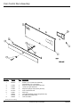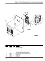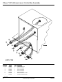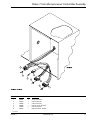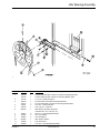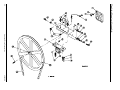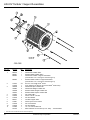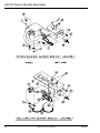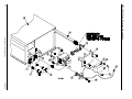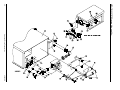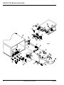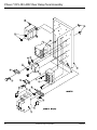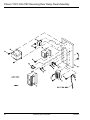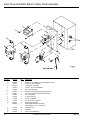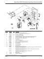
1
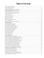
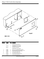
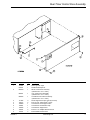
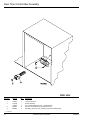
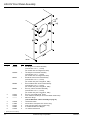
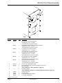
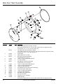
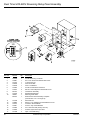
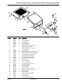
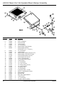
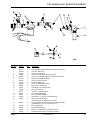
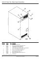
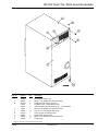
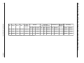
AD-30V / AD-50V
Parts Manual
Phase 7 / Dual Timer
(for models mfd. as of July 1, 2002)
American Dryer Corporation
88 Currant Road
Fall River, MA 02720-4781
Telephone: (508) 678-9000 / Fax: (508) 678-9447
E-mail: [email protected]
www.amdry.com
ADC Part No. 450438-5
Retain This Manual In A Safe Place For Future Reference
American Dryer Corporation products embody advanced concepts in engineering, design, and safety. If this product
is properly maintained, it will provide many years of safe, efficient, and trouble free operation.
ONLY qualified technicians should service this equipment.
OBSERVE ALL SAFETY PRECAUTIONS displayed on the equipment or specified in the installation manual included
with the dryer.
The following “FOR YOUR SAFETY” caution must be posted near the dryer in a prominent location.
FOR YOUR SAFETY
POUR VOTRE SÉCURITÉ
Do not store or use gasoline or
other flammable vapors and
liquids in the vicinity of this or
any other appliance.
Ne pas entreposer ni utiliser d’essence
ni d’autres vapeurs ou liquides
inflammables à proximité de cet appareil
ou de tout autre appareil.
We have tried to make this manual as complete as possible and hope you will find it useful. ADC reserves the right
to make changes from time to time, without notice or obligation, in prices, specifications, colors, and material, and to
change or discontinue models.
Important
For your convenience, log the following information:
DATE OF PURCHASE ____________________________________________________
MODEL NO. ______________
RESELLER’S NAME _________________________________________________________________________________
Serial Number(s) _____________________________________________________________________________________
____________________________________________________________________________________________________
____________________________________________________________________________________________________
Replacement parts can be obtained from your reseller or the ADC factory. When ordering replacement parts from the
factory, you can FAX your order to ADC at (508) 678-9447 or telephone your order directly to the ADC Parts Department
at (508) 678-9000. Please specify the dryer model number and serial number in addition to the description and part
number, so that your order is processed accurately and promptly.
The illustrations on the following pages may not depict your particular dryer exactly. The illustrations are a composite
of the various dryer models. Be sure to check the descriptions of the parts thoroughly before ordering.
“IMPORTANT NOTE TO PURCHASER”
Information must be obtained from your local gas supplier on the
instructions to be followed if the user smells gas. These
instructions must be posted in a prominent location near the dryer.
Table of Contents
Phase 7 OPL Control Door Assembly ....................................................................................................................................................................... 4
Dual Timer Control Door Assembly ........................................................................................................................................................................... 5
Coin Control Door Assembly ..................................................................................................................................................................................... 6
Phase 7 OPL Microprocessor Control Panel Assembly ........................................................................................................................................... 7
Phase 7 Coin Microprocessor Control Panel Assembly .......................................................................................................................................... 8
Dual Timer “Tap Touch” Controls .............................................................................................................................................................................. 9
Phase 7 OPL Microprocessor Control Box Assembly ............................................................................................................................................ 10
Phase 7 Coin Microprocessor Control Box Assembly ........................................................................................................................................... 11
Dual Timer Control Box Assembly .......................................................................................................................................................................... 12
Coin Vault Assembly ................................................................................................................................................................................................ 13
AD-30V Front Panel Assembly ................................................................................................................................................................................ 14
AD-50V Front Panel Assembly ................................................................................................................................................................................ 15
Main Door “Steel” Assembly .................................................................................................................................................................................... 16
Main Door Switch Assembly .................................................................................................................................................................................... 17
AD-30V Drop Hatch Lint Door Assembly ................................................................................................................................................................ 18
AD-30V Lint Trap Assembly .................................................................................................................................................................................... 19
AD-50V Lint Drawer / Lint Drawer Switch Assemblies ........................................................................................................................................... 20
Idler Bearing Assembly ............................................................................................................................................................................................ 21
Tumbler Bearing Assembly ..................................................................................................................................................................................... 22
AD-30V Tumbler / Support Assemblies .................................................................................................................................................................. 24
AD-50V Tumbler / Support Assemblies .................................................................................................................................................................. 25
AD-30V Non-Reversing Motor Mount Assembly .................................................................................................................................................... 26
AD-30V Reversing Motor Mount Assembly ............................................................................................................................................................ 28
AD-50V Non-Reversing Motor Mount Assembly .................................................................................................................................................... 30
AD-50V Reversing Motor Mount Assembly ............................................................................................................................................................ 32
AD-30V Sensor Bracket Assemblies ...................................................................................................................................................................... 34
AD-50V Sensor Bracket Assemblies ...................................................................................................................................................................... 36
AD-30V Gas Burner Assembly ................................................................................................................................................................................ 38
AD-30V CE Burner Assembly ................................................................................................................................................................................. 40
AD-50V Burner Assembly ........................................................................................................................................................................................ 42
AD-50V CE Burner Assembly ................................................................................................................................................................................. 44
Electric Oven Assembly ........................................................................................................................................................................................... 46
Gas Burner Sail Switch / Hi-Limit Assemblies ....................................................................................................................................................... 48
Phase 7 OPL Single-Phase (1ø) Rear Relay Panel Assembly ............................................................................................................................. 50
Phase 7 OPL 208-416V 3-Phase (3ø) Rear Relay Panel Assembly ..................................................................................................................... 52
Phase 7 OPL 460-480V Rear Relay Panel Assembly ........................................................................................................................................... 54
Phase 7 OPL 208-416V Reversing Rear Relay Panel Assembly .......................................................................................................................... 56
Phase 7 OPL 460-480V Reversing Rear Relay Panel Assembly .......................................................................................................................... 58
Dual Timer Single-Phase (1ø) Relay Panel Assembly ........................................................................................................................................... 60
Dual Timer 208-416V 3-Phase (3ø) Relay Panel Assembly .................................................................................................................................. 62
Dual Timer 460-480V Electric Relay Panel Assembly ........................................................................................................................................... 64
Dual Timer 208-416V Reversing Relay Panel Assembly ....................................................................................................................................... 65
Dual Timer 460-480V Reversing Relay Panel Assembly ....................................................................................................................................... 66
AD-30V Steam Coil / Air-Operated Steam Damper Assembly .............................................................................................................................. 67
AD-50V Steam Coil / Air-Operated Steam Damper Assembly .............................................................................................................................. 68
Fire Suppression System Assemblies .................................................................................................................................................................... 69
AD-30V Outer Top / Back Guard Assemblies ......................................................................................................................................................... 70
AD-50V Outer Top / Back Guard Assemblies ......................................................................................................................................................... 71
AD-30V Oven Component Application Chart ......................................................................................................................................................... 72
AD-50V Micro Electric Oven Component Application Chart .................................................................................................................................. 73
AD-50V Dual Timer Electric Oven Component Application Chart ......................................................................................................................... 74
Additional Parts Available / Tools Available ............................................................................................................................................................ 75
Phase 7 OPL Control Door Assembly
Illus. No.
Part No.
Qty.
1
883574
1
883746
1
883747
1
150321
117604
150317
102502
154011
102603
102601
2
4
2
1
2
1
1
2
3
4
5
6
7
8
4
Description
White OPL Control Door
(includes illus. nos. 1 and 3)
Coral Blue OPL Control Door
(includes illus. nos. 1 and 3)
Ivory OPL Control Door
(includes illus. nos. 1 and 3)
#10-32 x 1/2” Phillips Machine Screw
Noise Suppression Tape (sold by the foot)
#10-16 x 3/4” TORX PLUS® Screw
Control Door Support Rod
#10-32 Multi-Thread U-Nut
Control Door Rod Support Catch
Control Door Retainer Clip
American Dryer Corporation
450438 - 5
Dual Timer Control Door Assembly
Illus. No.
Part No.
Qty.
1
112301
870011
883550
1
1
1
883551
1
883552
1
117604
150317
102603
102601
102502
150321
154011
3
2
1
1
1
2
2
2
3
4
5
6
7
8
9
450438 - 5
Description
ADC Logo with Tape
Double Sided Tape Kit
White Control Door Assembly
(includes illus. nos. 2 and 3)
Ivory Control Door Assembly
(includes illus. nos. 2 and 3)
Coral Blue Control Door Assembly
(includes illus. nos. 2 and 3)
Noise Suppression Tape (sold by the foot)
#10-16 x 3/4” TORX PLUS® Screw
Control Door Rod Support Catch
Control Door Rod Retainer Clip
Control Door Support Rod
#10-32 x 1/2” Phillips Machine Screw
#10-32 Multi-Thread U-Nut
www.amdry.com
5
Coin Control Door Assembly
Illus. No.
Part No.
Qty.
1
823147*
1
2
3
4
5
6
7
117604
152014
117604
817141*
112301
160015
160104
160016
4
4
2
1
1
1
1
1
8
*
6
Description
Phase 7 Coin Control Door Assembly
(includes illus. nos. 1 through 5)
Neoprene Sponge Tape (sold by the foot)
1/4-20 Free Spin Wash Nut
Neoprene Sponge Tape (sold by the foot)
Coin Control Door Trim
ADC Logo
Lock with Hardware and Key (Keyed MK-100)
Key ONLY (Keyed MK-100)
Lock Cam ONLY
Specify color when ordering.
American Dryer Corporation
450438 - 5
Phase 7 OPL Microprocessor Control Panel Assembly
Illus. No.
Part No.
Qty.
1
2
3
112577
850984
887003
887024
1
1
1
1
887000
1
150005
153010
136097
136016
2
2
1
1
4
5
6
7
450438 - 5
Description
Phase 7 OPL Keypad
Phase 7 OPL Microprocessor Panel ONLY
Phase 7 OPL Microprocessor ONLY (with S.A.F.E.)
Phase 7 OPL Microprocessor ONLY (no S.A.F.E.)
(for models mfd. as of December 3, 2003)
Phase 7 OPL Microprocessor ONLY (with S.A.F.E.)
(for models mfd. prior to December 3, 2003)
#6-32 x 3/4” Phillips Round Head Machine Screw
#6 Star Washer
500 mA Fuse
5-Amp Fuse
www.amdry.com
7
Phase 7 Coin Microprocessor Control Panel Assembly
Illus. No.
Part No.
Qty.
1
2
3
137250
137270
887011
1
1
1
887012
1
887009
1
112575
153010
150005
152102
823145
818232
883774
1
4
4
4
1
1
1
4
5
6
7
8
9
8
Description
Phase 7 Coin Ribbon Cable
16” x 1” Large Character Display
Phase 7 Coin Board
(for models mfd. without S.A.F.E.)
Phase 7 Coin Board
(for models mfd. with S.A.F.E. and mfd. as of December 3, 2003)
Phase 7 Coin Board
(for models mfd. with S.A.F.E. and mfd. prior to December 3, 2003)
Phase 7 Keypad
#6 Internal and External Star Washers
#6-32 x 1/4” Phillips Round Head Machine Screw
M3 Metric Hex Nut
Phase 7 Coin Control Panel ONLY
25¢ Coin Acceptor
Hanke/Munzprufer Optic Switch ONLY
American Dryer Corporation
450438 - 5
Dual Timer “Tap Touch” Controls
Illus. No.
Part No.
Qty.
1
2
3
4
5
6
7
8
824298
824299
824175
122301
131932
120731
151000
882903
1
1
1
1
3
1
6
1
9
10
11
12
13
14
15
850392
153010
152000
150108
150110
112563
124104
124105
—
2
2
2
4
1
1
1
450438 - 5
Description
15 Minute Timer – 24 VAC
60 Minute Timer – 24 VAC
Red Pilot Light – 24 VAC
“Tap Touch” Switch
Relay SPST 24v
30-Position Terminal Block
#6-32 Pal Nut
Dual Timer Panel Complete
(includes illus. nos. 1 through 15)
Dual Timer Panel ONLY
#6 Star Washer
#6-32 Hex Nut
#8-32 x 1/2” Phillips Pan Head Machine Screw
#8-32 x 1/4” Phillips Round Head Machine Screw
Dual Timer Panel Overlay
Pure Touch Knob with Red Pointer
Pure Touch Knob with Blue Pointer
www.amdry.com
9
Phase 7 OPL Microprocessor Control Box Assembly
Illus. No.
Part No.
Qty.
1
2
3
4
5
6
7
122681
122676
122646
122683
122640
122706
122669
1
1
1
1
1
*
*
*
10
Description
10-Pin Connector
8-Pin Connector
2-Pin Connector
6-Pin Connector
9-Pin Connector
#20-16 U.M.N.L. Socket
Female Crimp Terminal
As needed.
American Dryer Corporation
450438 - 5
Phase 7 Coin Microprocessor Control Box Assembly
Illus. No.
Part No.
Qty.
1
2
3
4
5
6
122681
122676
122646
122669
122640
122706
1
1
1
*
1
*
*
Description
10-Pin Connector
8-Pin Connector
2-Pin Connector
Female Crimp Terminal
9-Pin Connector
#20-16 U.M.N.L. Socket
As needed.
450438 - 5
www.amdry.com
11
Dual Timer Control Box Assembly
Illus. No.
Part No.
Qty.
1
2
122641
122706
122801
150301
884252
1
*
1
2
1
3
4
*
12
Description
15-Pin Connector
Socket Terminal
Pin / Socket Extraction Tool … Not Illustrated
#8-18 x 7/16” Phillips Pan Head TEK Screw
Reversing Timer 24v (for reversing dual timer models Only)
As required.
American Dryer Corporation
450438 - 5
Coin Vault Assembly
Illus. No.
Part No.
Qty.
1
884050
1
4
823143
160028
875061
160105*
802020
1
1
1
1
1
5
6
7
8
9
802019
125915
802018
152014
102502
102601
102603
1
1
1
4
1
1
1
2
3
*
Description
Microprocessor Coin Vault Assembly Complete
(includes illus. nos. 1 through 6)
Microprocessor Coin Vault ONLY
Cam for 1/4” Turn Lock ONLY
1/4” Turn Lock with Key and Cam
1/4” Turn Mer-Pel Key ONLY
1/4” Turn Coin Box Assembly
(includes illus. nos. 2 through 5)
1/4” Turn Coin Box ONLY without Faceplate
High Security (Greenwald) Coin Box ONLY with Key (each keyed different)
1/4” Turn Coin Box Faceplate ONLY
1/4-20 Free Spin Wash Nut
Control Door Support Rod
Control Door Rod Retainer Clip
Control Door Rod Catch
Specify key number when ordering.
450438 - 5
www.amdry.com
13
AD-30V Front Panel Assembly
Illus. No.
Part No.
Qty.
1
822686*
1
822684*
1
883567
1
883568
1
883569
1
3
150313
150318
––––––
11
1
1
4
5
6
7
8
122002
170330
154215
102004
152223
1
1
2
2
2
2
*
14
Description
RH “Magnet” Front Panel Assembly
(includes illus. nos. 1, 7, and 8)
(for models mfd. as of August 22, 2007)
LH “Magnet” Front Panel Assembly
(includes illus. nos. 1, 7, and 8)
(for models mfd. as of August 22, 2007)
RH White Latch Front Panel Assembly
(includes illus. nos. 1, 5, and 6)
(for models mfd. prior to August 22, 2007)
RH Coral Blue Latch Front Panel Assembly
(includes illus. nos. 1, 5, and 6)
(for models mfd. prior to August 22, 2007)
RH Ivory Latch Front Panel Assembly
(includes illus. nos. 1, 5, and 6)
(for models mfd. prior to August 22, 2007)
#10-16 x 1/2” TORX PLUS® Screw
25 IP TORX PLUS® Bit (for removal of TORX® head screw)
Main Door Hinge
(refer to Main Door “Steel” Assembly on page 16)
Lint Drawer Switch
Friction Door Latch (latch door version Only)
5/32” Pop Rivet (latch door version Only)
0.750 Round Main Door Magnet
1/2” TORX® Head Screw
Specify color when ordering.
American Dryer Corporation
450438 - 5
AD-50V Front Panel Assembly
Illus. No.
Part No.
Qty.
1
822669*
1
822671
1
822673*
1
883137
1
883138
1
883139
1
3
150313
150318
––––––
11
1
1
4
––––––
1
5
6
7
8
170330
154215
102004
152223
1
2
2
2
2
*
Description
RH “Magnet” Front Panel Assembly
(includes illus. nos. 1, 7, and 8)
(for models mfd. as of June 18, 2007)
RH Stainless Steel “Magnet” Front Panel Assembly
(includes illus. nos. 1, 7, and 8)
(for models mfd. as of June 18, 2007)
LH “Magnet” Front Panel Assembly
(includes illus. nos. 1, 7, and 8)
(for models mfd. as of June 18, 2007)
RH White Front Panel Assembly
(includes illus. nos. 1, 5, and 6)
(for models mfd. prior to June 18, 2007)
RH Coral Blue Front Panel Assembly
(includes illus. nos. 1, 5, and 6)
(for models mfd. prior to June 18, 2007)
RH Ivory Front Panel Assembly
(includes illus. nos. 1, 5, and 6)
(for models mfd. prior to June 18, 2007)
#10-16 x 1/2” TORX PLUS® Screw
25 IP TORX PLUS® Bit (for removal of TORX® head screw)
Main Door Hinge
(refer to Main Door “Steel” Assembly on page 16)
Lint Drawer Switch
(refer to AD-50V Lint Drawer / Lint Drawer Switch Assemblies on page 20)
Friction Door Latch
5/32” Pop Rivet
0.750 Round Main Door Magnet
1/2” TORX® Head Screw
Specify color when ordering.
450438 - 5
www.amdry.com
15
Main Door “Steel” Assembly
Illus. No.
Part No.
Qty.
1
822661
1
881150
1
3
102354
401010
881152
1
1
1
4
5
6
150445
153031
881151
2
1
1
7
8
9
10
11
12
13
14
15
150445
150683
152014
151010
150120
150683
152014
881210
102211
170730
319298
2
3
3
1
1
3
3
1
1
1
2
2
16
16
Description
Magnet Black Main Door Assembly Complete
(for AD-50V models mfd. as of June 18, 2007 and AD-30V as of August 22, 2007)
(includes illus. nos. 1, 2, 8, 9, and 12 through 16)
Latch Black Main Door Assembly Complete
(for AD-50V models mfd. prior to June 18, 2007 and AD-30V prior to August 22, 2007)
(includes illus. nos. 1, 2, 8, and 9 through 15)
Door Gasket
Mastic Adhesive (5 oz. tube)
Black Top Hinge Block Assembly
(includes illus. nos. 3 and 4)
1/4-20 x 3/4” Black Cap Head Setscrew
1/4” Nylon Washer
Black Bottom Hinge Block Assembly
(includes illus. nos. 5 through 7)
1/4-20 x 3/4” Black Cap Head Setscrew
1/4-20 x 5/8” Black Carriage Bolt
1/4-20 Free Spin Wash Nut
#10-32 Black Hex Acorn Nut (latch models Only)
Door Screw (latch models Only)
1/4-20 x 5/8” Black Carriage Bolt
1/4-20 Free Spin Wash Nut
Black Main Door Handle ONLY
20-7/16” Door Glass
Adhesive (10.3 oz. cartridge)
Magnet Bracket
(for AD-50V models mfd. as of June 18, 2007 and AD-30V as of August 22, 2007)
American Dryer Corporation
450438 - 5
Main Door Switch Assembly
Illus. No.
Part No.
Qty.
1
2
3
4
5
6
150006
152013
153010
137005
122636
881211
2
2
2
1
2
1
881153
1
150301
2
7
450438 - 5
Description
#6-32 x 7/8” Phillips Pan Head Machine Screw
#6-32 Hex Nut
#6 Star Washer
Door Switch
Flag Terminal
Black Main Door Switch Housing ONLY
(includes illus. nos. 1 and 6)
Black Main Door Switch Housing Complete
(includes illus. nos. 1 through 4 and 6)
#8-18 x 7/16” Phillips Pan Head TEK Screw
www.amdry.com
17
AD-30V Drop Hatch Lint Door Assembly
Illus. No.
Part No.
Qty.
1
883680
1
883656
1
883657
1
802265*
1
117604
170226
160001
160016
160103
6
1
1
1
1
2
3
*
18
Description
White Drop Lint Door Assembly (non-coin Only)
(includes illus. nos. 1 through 3)
Coral Blue Drop Lint Door Assembly (non-coin Only)
(includes illus. nos. 1 through 3)
Ivory Drop Lint Door Assembly (non-coin Only)
(includes illus. nos. 1 through 3)
Drop Hatch Lint Door Assembly (coin Only)
(includes illus. nos. 1 through 3)
Noise Suppression Tape (sold by the foot)
Slide Latch (non-coin Only)
AD-100 Lock with Cam and Key (coin Only)
1-1/4” Cam ONLY (coin Only)
AD-100 Key ONLY (coin Only)
Specify color when ordering.
American Dryer Corporation
450438 - 5
AD-30V Lint Trap Assembly
Illus. No.
Part No.
Qty.
1
801070
1
800401
1
801069
800443
154200
150300
304100
800500
1
1
6
3
1
2
2
3
4
5
450438 - 5
Description
Lint Trap Assembly Complete (for 60 Hz models Only)
(includes illus. nos. 1 and 3 through 5)
Lint Trap Assembly Complete (for 50 Hz models Only)
(includes illus. nos. 1 and 3 through 5)
Lint Trap ONLY (for 60 Hz models Only)
Lint Trap ONLY (for 50 Hz models Only)
5/32” Pop Rivet
#10-16 x 1/2” Hex Washer TEK Screw
Lint Screen Holder
Lint Screen Assembly
www.amdry.com
19
AD-50V Lint Drawer / Lint Drawer Switch Assemblies
Illus. No.
Part No.
Qty.
1
850962**
1
883795
1
883796
1
883797
1
850968**
1
160001
160103
160052
117604
122116
122605
122701
122801
833123
1
1
1
7
1
*
*
1
1
818087
1
304136
150301
122700
122604
817032
1
2
*
*
1
2
3
4
5
6
7
8
9
10
*
**
20
Description
Lint Drawer Assembly (non-coin Only)
(for models mfd. as of January 1, 2003)
White Lint Drawer Assembly (non-coin Only)
(for models mfd. prior to January 1, 2003)
Coral Blue Lint Drawer Assembly (non-coin Only)
(for models mfd. prior to January 1, 2003)
Ivory Lint Drawer Assembly (non-coin Only)
(for models mfd. prior to January 1, 2003)
Locking Lint Basket Assembly (coin Only)
(includes illus. nos. 1, 2, and 10)
AD-100 Lock with Cam and Key (coin Only)
AD-100 Key ONLY (coin Only)
Lock Cam ONLY (coin Only)
Noise Suppression Tape (sold by the foot)
Lint Drawer Switch
4-Pin Connector (female)
Socket Terminal
Pin / Socket Extraction Tool … Not Illustrated
Lint Drawer Switch Box Assembly (for Phase 7 models Only)
(includes illus. nos. 3 through 6)
Lint Drawer Switch Box Assembly (for dual timer models Only)
(includes illus. nos. 3 through 6)
Lint Drawer Switch Box Cover ONLY
#8-18 x 7/16” Phillips Pan Head TEK Screw
Pin Terminal
4-Pin Connector (male)
Lint Bag
(for models mfd. as of January 1, 2003)
As required.
Specify color when ordering.
American Dryer Corporation
450438 - 5
Idler Bearing Assembly
Illus. No.
Part No.
Qty.
1
4
5
6
100100
100108
101129
100105
100112
154301
100705
882576
1
1
1
1
1
2
1
1
7
8
9
10
11
12
150617
153005
153004
801009
152004
150509
2
2
2
1
1
1
2
3
450438 - 5
Description
5L-660 V-Belt (tumbler to idler) for Non-Reversing Models ONLY
5L-680 V-Belt (tumbler to idler) for Reversing Models ONLY
9” x 2-1/2” Compound Pulley
4L-520 V-Belt for Non-Reversing Models ONLY
4L-610 V-Belt (idler to motor) for Reversing Models ONLY
5/16-18 x 1” Allen Setscrew
3/16” x 3/16” x 1-3/8” Key
Idler Bearing Assembly Complete
(includes illus. nos. 5 through 12)
3/8-16 x 1” Hex Head Machine Bolt
3/8” Lock Washer
3/8” Flat Washer
Idler Square Washer
5/16-18 Hex Nut
5/16-18 x 3” Hex Head Machine Bolt
www.amdry.com
21
Tumbler Bearing Assembly
22
American Dryer Corporation
450438 - 5
Tumbler Bearing Assembly
Illus. No.
Part No.
Qty.
1
2
3
4
880220
153025
152050
883387
1
4
4
1
882544
1
882543
882542
880779
1
1
1
880202
150601
153004
153004
153005
152005
154321
152004
150621
153002
153004
150501
102120
883386
100735
101100
101118
101110
100100
100108
150610
152004
1
2
2
2
2
2
2
2
2
4
6
4
1
1
1
1
1
1
1
1
2
2
5
6
7
8
9
10
11
12
13
14
15
16
17
18
19
20
21
22
23
24
450438 - 5
Description
1-3/4” Flange Bearing
9/16” Lock Washer
9/16-12 Hex Nut
Pillow Block Bearing Assembly Complete (for micro models Only)
(includes illus. nos. 4 through 18, 23, and 24)
Pillow Block Bearing Assembly Complete (for dual timer models Only)
(includes illus. nos. 4 through 16, 23, and 24)
Pillow Block Bearing Platform ONLY (for micro models Only)
Pillow Block Bearing Platform ONLY (for dual timer models Only)
1-3/8” Pillow Block Bearing (with Rotation Sensor Magnet illus. 17)
(for micro models Only)
1-3/8” Pillow Block Bearing (for dual timer models Only)
3/8-16 x 2” Hex Bolt
3/8” Flat Washer
3/8” Flat Washer
3/8” Lock Washer
3/8-16 Hex Nut
5/16-24 x 3/8” Setscrew
5/16-18 Hex Nut
5/16-18 x 1-1/2” Tap Bolt
5/16” Lock Washer
3/8” Flat Washer
5/16-18 x 3/4” Tap Bolt
Sintered 8 Magnet (for micro models Only)
Rotational Sensor Assembly (for micro models Only)
Shaft Key (for reversing models Only)
18” Pulley (for non-reversing models Only)
18-3/4” Pulley (for reversing models Only)
1” Taper Lock Bushing (for reversing models Only)
5L-660 V-Belt (tumbler to idler) for Non-Reversing Models ONLY
5L-680 V-Belt (tumbler to idler) for Reversing Models ONLY
5/16-18 x 1-1/2” Allen Setscrew
5/16-18 Hex Nut
www.amdry.com
23
AD-30V Tumbler / Support Assemblies
Illus. No.
1*
2
3
4
5
6
7
8
9
10
11
*
24
Part No.
Qty.
882519
882521
882522
1
1
1
882523
1
150313
150318
322002
322003
322066
322067
116002
100918
153004
882517
152027
153005
153004
115986
401010
40
1
2
2
2
2
1
4
4
1
4
4
4
1
1
Description
Galvanized Tumbler ONLY
Stainless Steel Tumbler ONLY
Galvanized Tumbler / Support Assemblies
(includes illus. nos. 1 through 3 and 5 through 11)
Stainless Steel Tumbler / Support Assemblies
(includes illus. nos. 1 through 3 and 5 through 11)
#10-16 x 1/2” TORX PLUS® Screw
25 IP TORX PLUS® Bit (for removal of TORX® head screw)
Galvanized Taper Tumbler Rib
Galvanized Straight Tumbler Rib
Stainless Steel Straight Tumbler Rib
Stainless Steel Tapered Tumbler Rib
Felt Collar ONLY
3/8-16 x 26-3/4” Tie Rod
3/8” Flat Washer
Tumbler Support ONLY
3/8-16 Nylon Insert Locknut
3/8” Lock Washer
3/8” Flat Washer
1/4” x 2” Felt Tumbler Pad
#847 Adhesive for Felt Collar (5.0 oz. tube) … Not Illustrated
Felt collar is not included and must be ordered separately.
American Dryer Corporation
450438 - 5
AD-50V Tumbler / Support Assemblies
Illus. No.
1*
2
3
4
5
6
7
8
9
10
11
*
Part No.
Qty.
800838
800736
800837
1
1
1
882683
1
150313
150318
301302
301311
301425
301426
116001
100903
153004
800616
152027
153005
153004
115986
401010
40
1
2
2
2
2
1
4
4
1
4
4
4
1
1
Description
Galvanized Tumbler ONLY
Stainless Steel Tumbler ONLY
Galvanized Tumbler and Support Assembly with Tapered Ribs
(includes illus. nos. 1 through 3 and 5 through 11)
Stainless Steel Tumbler and Support Assembly with Tapered Ribs
(includes illus. nos. 1 through 3 and 5 through 11)
#10-16 x 1/2” TORX PLUS® Crimptite Screw
25 IP TORX PLUS® Bit (for removal of TORX® head screw)
Galvanized Tumbler Rib (low rib) ONLY
Galvanized Tumbler Rib (high rib) ONLY
Stainless Steel Tumbler Rib
Stainless Steel Tapered Rib
Felt Collar ONLY
3/8-16 x 38-1/2” Tie Rod
3/8” Flat Washer
Tumbler Support ONLY
3/8-16 Nylon Insert Locknut
3/8” Lock Washer
3/8” Flat Washer
1/4” x 2” Felt Tumbler Pad
#847 Adhesive for Felt Collar (5.0 oz. tube) … Not Illustrated
Felt collar is not included and must be ordered separately.
450438 - 5
www.amdry.com
25
American Dryer Corporation
AD-30V Non-Reversing Motor Mount Assembly
26
450438 - 5
AD-30V Non-Reversing Motor Mount Assembly
Illus. No.
Part No.
Qty.
1
2
3
100105
100701
101104
101132
101131
1
1
1
1
1
101133
1
4
5
6
7
150501
153002
153001
181049
883572
4
4
4
1
1
8
122701
122801
137030
152004
153002
153001
117604
154000
850017
817075
8
1
1
4
4
4
4
4
1
1
803813
1
817080*
1
803810*
1
153050
100604
100702
153050
152006
120200
100007*
2
1
1
2
2
1
1
9
10
11
12
13
14
15
16
17
18
19
20
21
22
*
Description
4L-520 V-Belt (to idler motor)
3/16” x 3/16” x 1” Key
1/2” x 2” Motor Pulley (for use on 1ø – 60 Hz models Only)
5/8” x 2” Motor Pulley (for use on 3ø – 60 Hz models Only)
1/2” x 2-1/4” Motor Pulley
(for use on 1ø 50 Hz models mfd. as of August 22, 2002)
5/8” x 2-1/4” Motor Pulley
(for use on all 3ø 50 Hz and 1ø 50 Hz models mfd. prior to August 22, 2002)
5/16-18 x 3/4” Hex Head Machine Bolt
5/16” Lock Washer
5/16” Flat Washer
1/2 hp 120-230v 1ø 50/60 Hz Motor with Plug
1/2 hp 240v 1ø 50 Hz Motor with Plug (includes motor pulley)
(for 1ø 50 Hz models mfd. prior to August 22, 2002 Only)
Socket Terminal ONLY
Pin / Socket Extraction Tool … Not Illustrated
8-Pin Housing Connector
5/16-18 Hex Nut
5/16” Lock Washer
5/16” Flat Washer
Noise Suppression Tape (sold by the foot)
5/16-18 Nut
Non-Reversing Motor Mount ONLY (56Z frame)
1/2 hp 120-230v 1ø 60 Hz Motor Mount Assembly Complete with Plug Motor
(includes illus. nos. 2 through 7 and 13 through 20)
1/2 hp 240v 1ø 50 Hz Motor Mount Assembly Complete with Plug Motor
(includes illus. nos. 2 through 7 and 13 through 20)
1/2 hp 208/230/380/460v 3ø 60 Hz Motor Mount Assembly Complete
(includes illus. nos. 2 through 6 and 13 through 22)
1/2 hp 208/230/380/460v 3ø 50 Hz Non-Reversing Motor Mount Assembly Complete
(includes illus. nos. 2 through 6 and 13 through 22)
1/2” S.A.E. Flat Washer
12-1/2” Impellor with 1/2” Bore
1/8” x 1/8” x 1-1/2” Key
1/2” S.A.E. Flat Washer
1/2-20 Left Hand Jam Nut
3/8” 90° Connector
1/2 hp 208-460 3ø 50/60 Hz Motor
Specify voltage when ordering.
450438 - 5
www.amdry.com
27
AD-30V Reversing Motor Mount Assembly
28
American Dryer Corporation
450438 - 5
AD-30V Reversing Motor Mount Assembly
Illus. No.
Part No.
Qty.
1
2
3
100112
100701
101132
101133
120200
181003
150501
153002
153001
100007
120200
150501
153002
153001
154000
152004
153002
153001
850070
1
1
1
1
1
1
4
4
4
1
1
4
4
4
8
4
4
4
1
803802*
1
803803*
1
117604
153050
100702
100604
153050
152006
4
2
1
1
2
2
4
5*
6
7
8
9*
10
11
12
13
14
15
16
17
18
19
20
21
22
23
24
*
Description
4L-610 V-Belt (to idler motor)
3/16” x 3/16” x 1” Key
5/8” x 2” Motor Pulley (for 60 Hz models Only)
5/8” x 2-1/4” Motor Pulley (for 50 Hz models Only)
3/8” x 90° Connector
1/2 hp 208/230/380/460v 3ø 50/60 Hz Motor (56z frame)
5/16-18 x 3/4” Hex Head Machine Bolt
5/16” Lock Washer
5/16” Flat Washer
1/2 hp 208/230/380/460v 3ø 50/60 Hz Totally Enclosed, Fan-Cooled Motor (56z frame)
3/8” x 90° Connector
5/16-18 x 3/4” Hex Head Machine Bolt
5/16” Lock Washer
5/16” Flat Washer
5/16-18 Nut
5/16-18 Hex Nut
5/16” Lock Washer
5/16” Flat Washer
Motor Mount ONLY (56Z frame)
(includes illus. nos. 18 and 19)
Motor Mount Assembly Complete for 60 Hz Models ONLY
(includes illus. nos. 2 through 14 and 18 through 24)
Motor Mount Assembly Complete for 50 Hz Models ONLY
(includes illus. nos. 2 through 14 and 18 through 24)
Noise Suppression Tape (sold by the foot)
1/2” S.A.E. Flat Washer
1/8” x 1/8” x 1-1/2” Key
12-1/2” Impellor with 1/2” Bore
1/2” S.A.E. Flat Washer
1/2-20 Left Hand Jam Nut
Specify voltage when ordering.
450438 - 5
www.amdry.com
29
AD-50V Non-Reversing Motor Mount Assembly
30
American Dryer Corporation
450438 - 5
AD-50V Non-Reversing Motor Mount Assembly
Illus. No.
Part No.
Qty.
1
2
3
100105
100701
101132
101133
150501
153002
153001
100069
1
1
1
1
4
4
4
1
100068
1
122701
122801
137030
152004
153002
153001
117604
154000
850017
8
1
1
4
4
4
4
4
1
817029
1
817074
1
817080*
1
883271*
1
153050
100604
100702
153050
152006
120200
100007*
3
1
1
1
2
1
1
4
5
6
7
8
9
10
11
12
13
14
15
16
17
18
19
20
21
22
*
Description
4L-520 V-Belt (motor to idler)
3/16” x 3/16” x 1” Key
5/8” x 2” Motor Pulley (for use on 60 Hz models Only)
5/8” x 2-1/4” Motor Pulley (for use on 50 Hz models Only)
5/16-18 x 3/4” Hex Head Machine Bolt
5/16” Lock Washer
5/16” Flat Washer
3/4 hp 120-230v 1ø Totally Enclosed, Fan-Cooled Motor with Plug (56Z frame)
For 60 Hz Models ONLY
3/4 hp 240v 1ø Totally Enclosed, Fan-Cooled Motor with Plug (56Z frame)
For 50 Hz Models ONLY
Socket Terminal ONLY
Pin / Socket Extraction Tool … Not Illustrated
8-Pin Housing Connector
5/16-18 Hex Nut
5/16” Lock Washer
5/16” Flat Washer
Noise Suppression Tape (sold by the foot)
5/16-18 Nut
Non-Reversing Motor Mount ONLY with Gasket (56Z frame)
(includes illus. nos. 13 and 15)
3/4 hp 120-230v 1ø 60 Hz Totally Enclosed, Fan-Cooled
Motor Mount Assembly Complete with Plug Motor
(includes illus. nos. 2 through 7 and 13 through 20)
3/4 hp 240v 1ø 50 Hz Totally Enclosed, Fan-Cooled
Motor Mount Assembly Complete with Plug Motor
(includes illus. nos. 2 through 7 and 13 through 20)
1/2 hp 208/230/380/460v 3ø 60 Hz Motor Mount Assembly Complete
(includes illus. nos. 2 through 6 and 13 through 22)
1/2 hp 208/230/380/460v 3ø 50 Hz Motor Mount Assembly Complete
(includes illus. nos. 2 through 6 and 13 through 22)
1/2” S.A.E. Flat Washer
12-1/2” Impellor with 1/2” Bore
1/8” x 1/8” x 1-1/2” Key
1/2” S.A.E. Flat Washer
1/2-20 Left Hand Jam Nut
3/8” x 90° Connector
1/2 hp 208/230/380/460v 3ø 50/60 Hz Motor (56Z frame)
Specify voltage when ordering.
450438 - 5
www.amdry.com
31
AD-50V Reversing Motor Mount Assembly
32
American Dryer Corporation
450438 - 5
AD-50V Reversing Motor Mount Assembly
Illus. No.
Part No.
Qty.
1
2
3
100112
100701
101132
101133
120200
181003
150501
153002
153001
100007
120200
150501
153002
153001
154000
152004
153002
153001
850070
1
1
1
1
1
1
4
4
4
1
1
4
4
4
8
7
4
4
1
803802*
1
803803*
1
117604
153050
100702
100604
153050
152006
4
1
1
1
2
2
4
5*
6
7
8
9*
10
11
12
13
14
15
16
17
18
19
20
21
22
23
24
*
Description
4L-610 V-Belt (motor to idler)
3/16” x 3/16” x 1” Key
5/8” x 2” Motor Pulley (for 60 Hz models Only)
5/8” x 2-1/4” Motor Pulley (for 50 Hz models Only)
3/8” x 90° Connector
1/2 hp 208/230/380/460v 3ø 50/60 Hz (56Z frame)
5/16-18 x 3/4” Hex Head Machine Bolt
5/16” Lock Washer
5/16” Flat Washer
1/2 hp 208/230/380/460v 3ø 50/60 Hz Motor (56Z frame)
3/8” x 90° Connector
5/16-18 x 3/4” Hex Head Machine Bolt
5/16” Lock Washer
5/16” Flat Washer
5/16” Nut
5/16” Hex Nut
5/16” Lock Washer
5/16” Flat Washer
Motor Mount ONLY with Gasket (56Z frame)
(includes illus. nos. 18 and 19)
60 Hz Motor Mount Assembly Complete
(includes illus. nos. 2 through 14 and 18 through 24)
50 Hz Motor Mount Assembly Complete
(includes illus. nos. 2 through 14 and 18 through 24)
Noise Suppression Tape (sold by the foot)
1/2” S.A.E. Flat Washer
1/8” x 1/8” x 1-1/2” Key
12-1/2” Impellor with 1/2” Bore
1/2” S.A.E. Flat Washer
1/2-20 Left Hand Jam Nut
Specify voltage when ordering.
450438 - 5
www.amdry.com
33
AD-30V Sensor Bracket Assemblies
34
American Dryer Corporation
450438 - 5
AD-30V Sensor Bracket Assemblies
Illus. No.
Part No.
Qty.
1
880251
1
2
3
4
5
6
7
8
9
10
130301
153010
152000
121028
122701
122605
154007
150005
801424
1
2
2
2
4
1
2
2
1
11
12
13
14
15
16
17
18
19
20
21
22
23
24
305007
122604
122700
150301
150005
130111
130100
130103
130101
153010
152000
882535
121028
122701
122605
882534
1
1
4
2
5
1
1
1
1
5
5
1
4
4
1
1
25
818321
1
305007
122604
122700
122801
150301
1
1
4
1
2
26
27
28
450438 - 5
Description
1/4” Temperature Sensor Probe Assembly
(includes illus. nos. 1 and 5 through 8)
225° Hi-Limit Thermostat
#6 Star Washer
#6-32 Hex Nut
Insulated Terminal
Socket Terminal
4-Pin Connector (female)
1/4” Push-On Fastener
#6-32 x 1/4” Round Head Machine Screw
Microprocessor Sensor Bracket Assembly Complete
(includes illus. nos. 1 through 10)
Sensor Bracket ONLY
4-Pin Connector (male)
Pin Terminal
#8-18 x 7/16” Phillips Pan Head TEK Screw
#6-32 x 1/4” Phillips Round Head Machine Screw
130° Thermostat
150° Thermostat
225° Hi-Limit Thermostat
180° Thermostat
#6 Star Washer
#6-32 Hex Nut
Sensor Jumper
Insulated Terminal
Socket Terminal
4-Pin Connector (female)
Sensor Bracket Harness Assembly
(includes illus. nos. 22 through 24)
Noncomputer Sensor Bracket Assembly Complete
(includes illus. nos. 14 through 25)
Sensor Bracket ONLY
4-Pin Connector (male)
Pin Terminal
Pin / Socket Extraction Tool … Not Illustrated
#8-18 x 7/16” Phillips Pan Head TEK Screw
www.amdry.com
35
AD-50V Sensor Bracket Assemblies
36
American Dryer Corporation
450438 - 5
AD-50V Sensor Bracket Assemblies
Illus. No.
Part No.
Qty.
1
880251
1
2
3
4
5
6
7
8
9
10
130103
153010
152000
121028
122701
122605
154007
150005
817046
1
2
2
2
4
1
2
2
1
11
12
13
14
15
16
17
18
19
20
21
22
23
24
322214
122604
122700
150301
150005
130111
130100
130301
130101
153010
152000
882535
121028
122701
122605
882534
1
1
4
2
5
1
1
1
1
5
5
1
4
4
1
1
25
882536
1
322062
122604
122700
122801
150301
1
1
4
1
2
26
27
28
450438 - 5
Description
1/4” Temperature Sensor Probe Assembly
(includes illus. nos. 1 and 5 through 8)
225° Hi-Limit Thermostat
#6 Star Washer
#6-32 Hex Nut
Insulated Terminal
Socket Terminal
4-Pin Connector (female)
1/4” Push-On Fastener
#6-32 x 1/4” Phillips Round Head Machine Screw
Microprocessor Sensor Bracket Assembly Complete
(includes illus. nos. 1 through 10)
Micro Sensor Bracket ONLY
4-Pin Connector (male)
Pin Terminal
#8-18 x 7/16” Phillips Pan Head TEK Screw
#6-32 x 1/4” Phillips Round Head Machine Screw
130° Thermostat
150° Thermostat
225° Hi-Limit Thermostat
180° Thermostat
#6 Star Washer
#6-32 Hex Nut
Sensor Jumper
Insulated Terminal
Socket Terminal
4-Pin Connector (female)
Sensor Bracket Harness Assembly
(includes illus. nos. 22 through 24)
Noncomputer Sensor Bracket Assembly Complete
(includes illus. nos. 14 through 25)
Universal Sensor Bracket ONLY
4-Pin Connector (male)
Pin Terminal
Pin / Socket Extraction Tool … Not Illustrated
#8-18 x 7/16” Phillips Pan Head TEK Screw
www.amdry.com
37
American Dryer Corporation
AD-30V Gas Burner Assembly
38
450438 - 5
AD-30V Gas Burner Assembly
Illus. No.
Part No.
Qty.
1
2
3
4
141105
151001
150108
140820*
140806*
141230
318714
150309
128927
880960
884265
887133
2
2
2
2
2
1
1
5
1
1
1
1
883849
1
810031
150300
152013
141317
142809
830354
884279
1
9
2
1
1
1
1
128919
1
817060**
1
817061**
1
850858
882269*
880603***
1
1
1
5
6
7
8
9
10
11
12
13
14
15
16
17
18
Description
Large Tube Burner
#8-32 Pal Nut
#8-32 x 1/2” Phillips Pan Head Machine Screw
#29 Burner Orifice (natural gas)
#46 Burner Orifice (liquid propane gas)
1/2” Manifold (2-port)
1-Piece Gas Valve Bracket
#10-16 x 1/2” Hex Head TEK Crimptite Screw
1/2” 24 VAC (natural gas) Gas Valve
1/2” 24 VAC (liquid propane gas) Gas Valve
Ignitor Flame-Probe Assembly ONLY
Direct Spark Ignition Module
(for models mfd. as of March 1, 2004)
Direct Spark Ignition Module Kit
(for models mfd. prior to March 1, 2004)
Direct Spark Ignition Module Mounting Bracket
#10-16 x 1/2” Hex Washer TEK Screw
#6-32 Hex Nut
1/2” Bronze Union Elbow
1/2” x 29-1/8” Black Pipe
Direct Spark Ignition Control Wiring Harness
High Voltage Gray Carbon Wire with Terminal
(for models mfd. as of March 1, 2004)
High Voltage Red Wire
(for models mfd. prior to March 1, 2004)
Direct Spark Ignition Burner Assembly Complete (less orifice) (natural gas)
(includes illus. nos. 1 through 3 and 5 through 18)
Direct Spark Ignition Burner Assembly Complete (less orifice) (liquid propane gas)
(includes illus. nos. 1 through 3 and 5 through 18)
Burner Box ONLY
AD-30V Liquid Propane Conversion Kit (includes orifices)
Steam to Gas Interface Assembly
*
Consult factory for elevations over 2,000 feet.
** Burner orifices are not included and must be ordered separately.
*** Needed when converting steam heat to gas heat.
450438 - 5
www.amdry.com
39
American Dryer Corporation
AD-30V CE Burner Assembly
40
450438 - 5
AD-30V CE Burner Assembly
Illus. No.
Part No.
Qty.
1
850858
801190**
1
1
817208**
1
882041**
884265
152013
150309
141105
150108
887145
1
1
2
5
2
2
1
887209
1
151001
140819*
140804*
141230
318700
150300
128933
883255
141317
142809
318700
150309
810029
2
2
2
1
1
2
1
1
1
1
2
4
1
810031
1
142935
150005
154004
150300
802799
150303
122200
122404
105500
319202
154002
130201
319704
152013
884279
1
2
1
9
1
2
1
1
1
1
1
1
1
2
1
128919
1
830354
1
2
3
4
5
6
7
8
9
10
11
12
13
14
15
16
17
18
19
20
21
22
23
24
25
26
27
28
29
30
31
32
33
Description
Burner Box ONLY
Natural Gas Burner Assembly
(includes illus. nos. 1 through 8 and 10 through 32)
Liquid Propane Gas Burner Assembly
(includes illus. nos. 1 through 8 and 10 through 32)
CE Liquid Propane Conversion Kit
Ignitor Flame-Probe (no wires)
#6-32 Hex Nut
#10-16 x 1/2” Hex Head TEK Crimptite Screw
Large Tube Burner
#8-32 x 1/2” Pan Head Machine Screw
CE Direct Spark Ignition Module
(for models mfd. as of June 10, 2004)
CE Direct Spark Ignition Module Kit
(for models mfd. prior to June 10, 2004)
#8-32 Pal Nut
#30 Burner Orifice (natural gas)
#48 Burner Orifice (liquid propane gas)
1/2” Manifold (2-port)
Pipe Bracket (bent)
#10-16 x 1/2” Hex Washer TEK Screw
1/2” 24 VAC CE Gas Valve (natural gas)
1/2” 24 VAC CE Gas Valve (liquid propane gas)
1/2” Bronze Union Elbow
1/2” x 29-1/8” Pipe
Pipe Bracket (bent)
#10-16 x 1/2” Hex Head TEK Crimptite Screw
Direct Spark Ignition Module Mounting Bracket
(for models mfd. as of June 10, 2004)
Direct Spark Ignition Module Mounting Bracket
(for models mfd. prior to June 10, 2004)
1/2” B.S.P.T. x 1/2” N.P.T. Transition Coupling
#6-32 x 1/4” Round Head Machine Screw
Twin Speed Nut
#10-16 x 1/2” Hex Washer TEK Screw
Sail Switch Top and Switch Bracket
#4 x 3/4” Pan Head Machine Screw
SPST Sail Switch (for micro models Only)
SPDT Sail Switch (for dual timer models Only)
Sail Switch Actuator Rod
Sail Switch Damper (flat)
1/8” Push-On Fastener
330° Hi-Limit Thermostat
Hi-Limit Mounting Bracket
#6-32 Hex Nut
High Voltage Gray Carbon Wire with Terminal
(for models mfd. as of June 10, 2004)
High Voltage Red Wire
(for models mfd. prior to June 10, 2004)
Direct Spark Ignition Control Wiring Harness
*
Consult factory for elevations over 2,000 feet.
** Burner orifices are not included and must be ordered separately.
*** Contact ADC factory with serial number of dryer and country destination.
450438 - 5
www.amdry.com
41
AD-50V Burner Assembly
42
American Dryer Corporation
450438 - 5
AD-50V Burner Assembly
Illus. No.
1
2
3
4*
5
6
7
8
9
10
11
12
13
14
15
16
17
18
—
—
Part No.
Qty.
141105
151001
150108
140820
140806
141232
150309
318714
128927
880960
884265
882537
150300
810029
887133
3
3
3
3
3
1
3
1
1
1
1
1
2
1
1
887849
1
152013
141317
142809
830354
884279
2
1
1
1
1
128919
1
817062***
1
817063***
1
850899
882271*
883310**
1
1
1
Description
Large Tube Burner
#8-32 Pal Nut
#8-32 x 1/2” Pan Head Machine Screw
#29 Natural Gas Burner Orifice
#46 Liquid Propane Burner Orifice
1/2” Manifold (3-port)
#10-16 x 1/2” Hex Head TEK Crimptite Screw
Gas Valve Bracket (horizontal)
1/2” 24 VAC Redundant (natural gas) Gas Valve
1/2” 24 VAC Redundant (liquid propane gas) Gas Valve
Ignitor Flame-Probe ONLY
Flame-Probe Wire
#10-16 x 1/2” Hex Washer TEK Screw
Direct Spark Ignition Module Mounting Bracket
Direct Spark Ignition Module
(for models mfd. as of March 1, 2004)
Direct Spark Ignition Module
(for models mfd. prior to March 1, 2004)
#6-32 Hex Nut
1/2” Bronze Union Elbow
1/2” x 29-1/8” Black Nipple
Direct Spark Ignition Control Wiring Harness
High Voltage Gray Carbon Wire with Terminal
(for models mfd. as of March 1, 2004)
High Voltage Red Wire
(for models mfd. prior to March 1, 2004)
Direct Spark Ignition Burner Assembly Complete (natural gas)
(includes illus. nos. 1 through 3 and 5 through 18)
Direct Spark Ignition Burner Assembly Complete (liquid propane gas)
(includes illus. nos. 1 through 3 and 5 through 18)
Burner Box ONLY
ADG-50V Liquid Propane Conversion Kit (includes orifices)
Steam to Gas Transition Plate … Not Illustrated
*
Consult factory for elevations over 2,000 feet.
** Needed when converting dryer from steam heat to gas heat.
*** Burner orifices are not included and must be ordered separately.
450438 - 5
www.amdry.com
43
AD-50V CE Burner Assembly
44
American Dryer Corporation
450438 - 5
AD-50V CE Burner Assembly
Illus. No.
Part No.
Qty.
1
2
884265
887145
1
1
887209
1
810029
150309
141105
150108
152013
151001
140819*
140804*
141232
318700
150300
128933
883255
141317
142809
850899
817174**
1
6
3
3
2
3
3
3
1
3
9
1
1
1
1
1
1
817207**
1
––––––****
883310***
142935
319704
150001
151000
154004
130201
802799
150303
122200
122404
105500
319202
154002
830354
884279
1
1
1
1
2
2
1
1
1
2
1
1
1
1
1
1
1
128919
1
3
4
5
6
7
8
9
10
11
12
13
14
15
16
17
18
19
20
21
22
23
24
25
26
27
28
29
30
*
**
***
****
Description
Ignitor Flame-Probe ONLY
CE Direct Spark Ignition Module
(for models mfd. as of June 10, 2004)
CE Direct Spark Ignition Module
(for models mfd. prior to June 10, 2004)
Direct Spark Ignition Module Mounting Bracket Assembly
#10-16 x 1/2” Hex Head TEK Crimptite Screw
Large Tube Burner
#8-32 x 1/2” Pan Head Machine Screw
#6-32 Hex Nut
#8-32 Pal Nut
#30 Burner Orifice (natural gas)
#48 Burner Orifice (liquid propane gas)
1/2” Manifold (3-port)
Pipe Bracket (bent)
#10-16 x 1/2” Hex Washer TEK Screw
CE Gas Valve (natural gas)
CE Gas Valve (liquid propane gas)
1/2” Bronze Union Elbow
1/2” x 29-1/8” Pipe
Burner Box ONLY
Natural Gas Burner Assembly Complete
(includes illus. nos. 1 through 8, 10 through 28, and 30)
Liquid Propane Gas Burner Assembly Complete
(includes illus. nos. 1 through 8, 10 through 28, and 30)
Liquid Propane Conversion Kit
Steam to Gas Interface Plate … Not Illustrated
1/2” Coupling
Hi-Limit Mounting Bracket
#6-32 x 1/2” Round Head Machine Screw
#6-32 Pal Nut
Twin Speed Nut
330° Hi-Limit Thermostat
Sail Switch Top and Switch Bracket
#4 x 3/4” Pan Head Machine Screw
SPST Sail Switch (for micro models Only)
SPDT Sail Switch (for dual timer models Only)
Sail Switch Actuator Rod
Sail Switch Damper (flat)
1/8” Push-On Fastener
Direct Spark Ignition Control Wiring Harness
High Voltage Gray Carbon Wire with Terminal
(for models mfd. as of March 1, 2004)
High Voltage Red Wire
(for models mfd. prior to March 1, 2004)
Consult factory for elevations over 2,000 feet.
Burner orifices are not included and must be ordered separately.
Needed when converting from steam heat to gas heat.
Contact ADC factory with serial number of dryer and country destination.
450438 - 5
www.amdry.com
45
Electric Oven Assembly
46
American Dryer Corporation
450438 - 5
Electric Oven Assembly
Illus. No.
Part No.
Qty.
1
803007
––––––*
––––––*
150300
802800
802801
1
1
—
2
1
1
802804
1
154004
150300
802799
122200
122404
150303
105500
319202
154002
150300
803100
320611
150301
130400
150300
154001
121010
152014
––––––*
150207
120081
120080
152008
121011*
––––––*
153009
321301
883310**
1
2
1
1
1
2
1
1
1
2
1
1
2
1
2
2
1
3
1
2
—
—
—
—
—
—
1
1
2
3
4
5
6
7
8
9
10
11
12
13
14
15
16
17
18
19
20
21
22
23
24
25
26
27
28
29
30
*
**
Description
Large Electric Oven Box ONLY
Electric Oven Assembly Complete
Electric Element
#10-16 x 1/2” Hex Washer TEK Screw
Sail Switch Box with Bracket and Cover ONLY
Sail Switch Box Assembly Complete
(includes illus. nos. 4 through 12)
Sail Switch Box Assembly Complete (for dual timer CE models Only)
(includes illus. nos. 4 through 12)
Twin Speed Nut
#10-16 x 1/2” Hex Washer TEK Screw
Sail Switch Box Cover and Bracket ONLY
SPST Sail Switch
SPDT Sail Switch (for dual timer CE models Only)
#4 x 3/4” Pan Head Machine Screw
Sail Switch Actuator Rod
Sail Switch Damper (flat)
1/8” Push-On Fastener
#10-16 x 1/2” Hex Washer TEK Screw
Electric Oven Front Cover
Large Relay Box Cover
#8-18 x 7/16” Phillips Pan Head TEK Screw
290° Hi-Limit Thermostat
#10-16 x 1/2” Hex Washer TEK Screw
#10-24 Speed Nut
L-70 Ground Lug
1/4-20 Free Spin Wash Nut
Oven Relay
#10-24 x 1/2” Phillips Pan Head Machine Screw
Internal Ceramic Insulator (2 per element)
External Ceramic Insulator (2 per element)
#10-32 Hex Nut (4 per element)
Bus Bar (sold by the foot)
Oven Wire
#10 Star Washer (2 per element)
Large Electric Oven Right Side Cover
Steam to Electric Transition Plate … Not Illustrated
Refer to Electric Oven Component Application Charts on page 72 through page 74.
Needed when converting dryer from steam heat to electric heat.
450438 - 5
www.amdry.com
47
Gas Burner Sail Switch / Hi-Limit Assemblies
48
American Dryer Corporation
450438 - 5
Gas Burner Sail Switch / Hi-Limit Assemblies
Illus. No.
Part No.
Qty.
1
2
3
4
5
154004
150300
802799
150303
122200
122404
105500
319202
154002
802800
802801
1
2
1
2
1
1
1
1
1
1
1
802804
1
10
––––––
1
11
12
13
14
15
150300
319704
151000
150001
130201
2
1
2
2
1
6
7
8
9
450438 - 5
Description
Twin Speed Nut
#10-16 x 1/2” Hex Washer TEK Screw
Sail Switch Box Cover and Bracket ONLY
#4 x 3/4” Pan Head Machine Screw
SPST Sail Switch
SPDT Sail Switch (for dual timer CE models Only)
Sail Switch Actuator Rod
Sail Switch Damper (flat)
1/8” Push-On Fastener
Sail Switch Box with Cover and Bracket ONLY
Sail Switch Assembly Complete
(includes illus. nos. 1 through 9)
Sail Switch Assembly Complete (for dual timer CE models Only)
(includes illus. nos. 1 through 9)
1/2” Pipe
(refer to Burner Assembly on page 38 through page 44)
#10-16 x 1/2” Hex Washer TEK Screw
Hi-Limit Mounting Bracket
#6-32 Pal Nut
#6-32 x 1/2” Phillips Round Head Machine Screw
330° Hi-Limit Thermostat
www.amdry.com
49
American Dryer Corporation
Phase 7 OPL Single-Phase (1ø) Rear Relay Panel Assembly
50
450438 - 5
Phase 7 OPL Single-Phase (1ø) Rear Relay Panel Assembly
Illus. No.
Part No.
Qty.
1
2
3
4
5
151000
150300
150008
120716
322812
822796
2
2
2
1
1
1
830153
1
822798
1
830273
1
830131
1
830426
1
830151
822799
822792
830141
136008
136057
136049
150301
150297
152004
121010
153002
132495
121300
131932
1
1
1
1
*
*
*
4
1
1
1
1
1
3
1
6
7
8
9
10
11
12
13
14
15
16
*
Description
#6-32 Pal Nut
#10-16 x 1/2” Hex Washer TEK Screw
#6-32 x 1-1/4” Phillips Pan Head Machine Screw
2-Position Terminal Block
Rear Electric Mounting Plate ONLY
Rear Electric Panel Assembly Complete – 115 Volt (for gas models Only)
(includes illus. nos. 1 through 14)
Rear Electric Panel Assembly Complete – 115 Volt (for steam models Only)
(includes illus. nos. 1 through 14)
Rear Electric Panel Assembly Complete – 208-240 Volt (for gas models Only)
(includes illus. nos. 1 through 14)
Rear Electric Panel Assembly Complete – 208-240 Volt (for steam models Only)
(includes illus. nos. 1 through 14)
Rear Electric Panel Assembly Complete – 208-240 Volt (for electric models Only)
(includes illus. nos. 1 through 14 and 16)
Rear Electric Panel Assembly Complete – 380-416 Volt
(for electric models with 1ø motors Only)
(includes illus. nos. 1 through 14 and 16)
Transformer Assembly – 115 Volt
Transformer Assembly – 208-240 Volt (for gas and steam models Only)
Transformer Assembly – 208-240 Volt (for electric models Only)
Transformer Assembly – 380-416 Volt
Fuse Holder
1/2-Amp (Slo-Blo) Fuse (for 208-416 volt models Only)
3/4-Amp (Slo-Blo) Fuse (for 115 volt models Only)
#8-18 x 7/16” Phillips Pan Head TEK Screw
#10 x 1/2” Green Hex Washer TEK Screw
5/16-18 Hex Nut
L-70 Ground Lug
5/16” Lock Washer
3-Pole Contactor
Open / Closed Bushing
24V SPST Relay (for electric models Only)
Quantity is 1 for 115v and 380-416v. Quantity is 2 for 208-240v.
450438 - 5
www.amdry.com
51
American Dryer Corporation
Phase 7 OPL 208-416V 3-Phase (3ø) Rear Relay Panel Assembly
52
450438 - 5
Phase 7 OPL 208-416V 3-Phase (3ø) Rear Relay Panel Assembly
Illus. No.
Part No.
Qty.
1
2
3
4
5
151000
150300
150008
120701
322812
830154
2
2
2
1
1
1
830322
1
830157
1
––––––*
1
803834
1
830140
1
822799
822792
822784
830141
136008
136057
150301
150297
152004
121010
153002
132495
121300
131932
1
1
1
1
1 or 2
1 or 2
2 or 4
1
1
1
1
1
3
1
6
7
8
9
10
11
12
13
14
15
16
*
Description
#6-32 Pal Nut
#10-16 x 1/2” Hex Washer TEK Screw
#6-32 x 1-1/4” Phillips Pan Head Machine Screw
4-Position Terminal Block
Rear Electric Mounting Plate ONLY
Rear Electric Panel Assembly Complete – 208-240 Volt (for gas models Only)
(includes illus. nos. 1 through 14)
Rear Electric Panel Assembly Complete – 208-240 Volt (for steam models Only)
(includes illus. nos. 1 through 14)
Rear Electric Panel Assembly Complete – 208-240 Volt (for electric models Only)
(includes illus. nos. 1 through 14 and 16)
Rear Electric Panel Assembly Complete – 380-416 Volt (for gas models Only)
(includes illus. nos. 1 through 14)
Rear Electric Panel Assembly Complete – 380-416 Volt (for steam models Only)
(includes illus. nos. 1 through 14)
Rear Electric Panel Assembly Complete – 380-416 Volt
(for electric models with 3ø motors Only)
(includes illus. nos. 1 through 14 and 16)
Transformer Assembly – 208-240 Volt (for gas and steam models Only)
Transformer Assembly – 208-240 Volt (for electric models Only)
Transformer Assembly – 380-416 Volt (for gas and steam models Only)
Transformer Assembly – 380-416 Volt (for electric models Only)
Fuse Holder
1/2-Amp (Slo-Blo) Fuse
#8-18 x 7/16” Phillips Pan Head TEK Screw
#10 x 1/2” Green Hex Washer TEK Screw
5/16-18 Hex Nut
L-70 Ground Lug
5/16” Lock Washer
3-Pole Contactor
Open / Closed Bushing
24V SPST Relay (for electric models Only)
Not available at time of printing.
450438 - 5
www.amdry.com
53
Phase 7 OPL 460-480V Rear Relay Panel Assembly
54
American Dryer Corporation
450438 - 5
Phase 7 OPL 460-480V Rear Relay Panel Assembly
Illus. No.
1
2
3
4
5
6
7
8
9
10
11
12
13
14
15
16
17
450438 - 5
Part No.
Qty.
150300
150008
120701
135501
824221
120768
120765
150301
150297
152004
121010
153002
132495
322812
830263
2
2
1
1
1
2
2
4
2
1
2
1
1
1
1
830137
1
830199
1
151000
131932
112075
2
1
1
Description
#10-16 x 1/2” Hex Washer TEK Screw
#6-32 x 1-1/4” Phillips Pan Head Machine Screw
4-Position Terminal Block
2-Pole 1-Amp Circuit Breaker
Transformer Assembly – 460-480 Volt
35 x 15mm Din Rail
Standard End Bracket
#8-18 x 7/16” Phillips Pan Head TEK Screw
#10 x 1/2” Green Hex Washer TEK Screw
5/16-18 Hex Nut
L-70 Ground Lug
5/16” Lock Washer
3-Pole Contactor
Rear Electric Mounting Plate ONLY
Rear Electric Panel Assembly Complete – 460-480 Volt (for gas models Only)
(includes illus. nos. 1 through 15 and 17)
Rear Electric Panel Assembly Complete – 460-480 Volt (for steam models Only)
(includes illus. nos. 1 through 15 and 17)
Rear Electric Panel Assembly Complete – 460-480 Volt (for electric models Only)
(includes illus. nos. 1 through 17)
#6-32 Pal Nut
24V SPST Relay (for electric models Only)
Ground Label
www.amdry.com
55
Phase 7 OPL 208-416V Reversing Rear Relay Panel Assembly
56
American Dryer Corporation
450438 - 5
Phase 7 OPL 208-416V Reversing Rear Relay Panel Assembly
Illus. No.
Part No.
Qty.
1
2
3
4
5
150300
150008
120701
132497
822799
822792
822784
136008
136057
150301
150297
152004
121010
153002
132495
322812
822771
2
2
1
1
1
1
1
1 or 2
1 or 2
2 or 4
2
1
2
1
1
1
1
830167
1
822789
1
822783
1
830117
1
818397
1
151000
120765
131932
2
1
1
6
7
8
9
10
11
12
13
14
15
16
17
450438 - 5
Description
#10-16 x 1/2” Hex Washer TEK Screw
#6-32 x 1-1/4” Phillips Pan Head Machine Screw
4-Position Terminal Block
3-Pole Reversing Contactor
Transformer Assembly – 208-240 Volt (for gas and steam models Only)
Transformer Assembly – 208-240 Volt (for electric models Only)
Transformer Assembly – 380-416 Volt
Fuse Holder
1/2-Amp (Slo-Blo) Fuse
#8-18 x 7/16” Phillips Pan Head TEK Screw
#10 x 1/2” Green Hex Washer TEK Screw
5/16-18 Hex Nut
L-70 Ground Lug
5/16” Lock Washer
3-Pole Contactor
Rear Electric Mounting Plate ONLY
Rear Electric Panel Assembly Complete – 208-240 Volt (for gas models Only)
(includes illus. nos. 1 through 16)
Rear Electric Panel Assembly Complete – 208-240 Volt (for steam models Only)
(includes illus. nos. 1 through 16)
Rear Electric Panel Assembly Complete – 208-240 Volt (for electric models Only)
(includes illus. nos. 1 through 17)
Rear Electric Panel Assembly Complete – 380-416 Volt (for gas models Only)
(includes illus. nos. 1 through 16)
Rear Electric Panel Assembly Complete – 380-416 Volt (for steam models Only)
(includes illus. nos. 1 through 16)
Rear Electric Panel Assembly Complete – 380-416 Volt (for electric models Only)
(includes illus. nos. 1 through 17)
#6-32 Pal Nut
Standard End Bracket
24V SPST Relay (for electric models Only)
www.amdry.com
57
Phase 7 OPL 460-480V Reversing Rear Relay Panel Assembly
58
American Dryer Corporation
450438 - 5
Phase 7 OPL 460-480V Reversing Rear Relay Panel Assembly
Illus. No.
1
2
3
4
5
6
7
8
9
10
11
12
13
14
15
16
17
18
450438 - 5
Part No.
Qty.
150300
150008
120701
135501
824221
120768
120765
150301
150297
152004
121010
153002
132495
322812
830147
2
2
1
1
1
2
2
4
2
1
2
1
1
1
1
830103
1
824371
1
151000
132497
112075
131932
2
1
1
1
Description
#10-16 x 1/2” Hex Washer TEK Screw
#6-32 x 1-1/4” Phillips Pan Head Machine Screw
4-Position Terminal Block
2-Pole 1-Amp Circuit Breaker
Transformer Assembly – 460-480 Volt
35 x 15mm Din Rail
Standard End Bracket
#8-18 x 7/16” Phillips Pan Head TEK Screw
#10 x 1/2” Green Hex Washer TEK Screw
5/16-18 Hex Nut
L-70 Ground Lug
5/16” Lock Washer
3-Pole Contactor
Rear Electric Mounting Plate ONLY
Rear Electric Panel Assembly Complete – 460-480 Volt (for gas models Only)
(includes illus. nos. 1 through 17)
Rear Electric Panel Assembly Complete – 460-480 Volt (for steam models Only)
(includes illus. nos. 1 through 17)
Rear Electric Panel Assembly Complete – 460-480 Volt (for electric models Only)
(includes illus. nos. 1 through 18)
#6-32 Pal Nut
3-Pole Reversing Contactor
Ground Label
24V SPST Relay (for electric models Only)
www.amdry.com
59
Dual Timer Single-Phase (1ø) Relay Panel Assembly
60
American Dryer Corporation
450438 - 5
Dual Timer Single-Phase (1ø) Relay Panel Assembly
Illus. No.
Part No.
Qty.
1
2
3
4
5
151000
150300
150008
120716
322817
882662
2
2
2
1
1
1
882663
1
818395
1
882667
1
882652
882653
818396
882654
136008
136049
136057
150301
150297
152004
121010
153002
132459
121300
1
1
1
1
*
*
*
*
1
1
1
1
1
3
6
7
8
9
10
11
12
13
14
15
*
Description
#6-32 Pal Nut
#10-16 x 1/2” Hex Washer TEK Screw
#6-32 x 1-1/4” Phillips Pan Head Machine Screw
2-Position Terminal Block
Rear Electric Mounting Plate ONLY
Rear Electric Panel Assembly Complete – 120 Volt
(includes illus. nos. 1 through 14)
Rear Electric Panel Assembly Complete – 208-240 Volt (for gas and steam models Only)
(includes illus. nos. 1 through 14)
Rear Electric Panel Assembly Complete – 208-240 Volt
(for electric models mfd. with single-phase [1ø] motor Only)
(includes illus. nos. 1 through 14)
Rear Electric Panel Assembly Complete – 380-416 Volt
(for electric models mfd. with single-phase [1ø] motor Only)
(includes illus. nos. 1 through 14)
Transformer Assembly – 120 Volt
Transformer Assembly – 208-240 Volt (for gas and steam models Only)
Transformer Assembly – 208-240 Volt (for electric models Only)
Transformer Assembly – 380-416 Volt
Fuse Holder
3/4-Amp (Slo-Blo) Fuse – 120 Volt
1/2-Amp (Slo-Blo) Fuse – 208-416 Volt
#8-18 x 7/16” Phillips Pan Head TEK Screw
#10 x 1/2” Green Hex Washer TEK Screw
5/16-18 Hex Nut
L-70 Ground Lug
5/16” Lock Washer
3-Pole Contactor
Open / Closed Bushing
Quantity is 1 for 115v and 380-416v. Quantity is 2 for 208-240v.
450438 - 5
www.amdry.com
61
American Dryer Corporation
Dual Timer 208-416V 3-Phase (3ø) Relay Panel Assembly
62
450438 - 5
Dual Timer 208-416V 3-Phase (3ø) Relay Panel Assembly
Illus. No.
Part No.
Qty.
1
2
3
4
5
151000
150300
150008
120701
322817
882664
2
2
2
1
1
1
818400
1
882665
1
882653
818396
882654
136008
136057
150301
150297
152004
121010
153002
132459
121300
1
1
1
*
*
*
1
1
1
1
1
3
6
7
8
9
10
11
12
13
14
15
*
Description
#6-32 Pal Nut
#10-16 x 1/2” Hex Washer TEK Screw
#6-32 x 1-1/4” Phillips Pan Head Machine Screw
4-Position Terminal Block (for models mfd. with 3-phase [3ø] motors)
Rear Electric Mounting Plate ONLY
Rear Electric Panel Assembly Complete – 208-240 Volt (for gas and steam models Only)
(includes illus. nos. 1 through 14)
Rear Electric Panel Assembly – 208-240 Volt (for electric models Only)
(includes illus. nos. 1 through 14)
Rear Electric Panel Assembly Complete – 380-416 Volt (for gas and steam models Only)
(includes illus. nos. 1 through 14)
Transformer Assembly – 208-240 Volt (for gas and steam models Only)
Transformer Assembly – 208-240 Volt (for electric models Only)
Transformer Assembly – 380-416 Volt
Fuse Holder
1/2-Amp (Slo-Blo) Fuse
#8-18 x 7/16” Phillips Pan Head TEK Screw
#10 x 1/2” Green Hex Washer TEK Screw
5/16-18 Hex Nut
L-70 Ground Lug
5/16” Lock Washer
3-Pole Contactor
Open / Closed Bushing
Quantity is 1 for 380-416v and 2 for 208-240v.
450438 - 5
www.amdry.com
63
Dual Timer 460-480V Electric Relay Panel Assembly
Illus. No.
64
Part No.
Qty.
1
2
3
4
5
6
7
8
9
10
11
12
150009
120701
824161
135501
120768
150301
150297
152004
121010
153002
132459
322817
830262
2
1
1
1
2
4
1
1
1
1
1
1
1
13
14
15
151000
120765
121300
2
4
3
Description
#6-32 x 1-1/2” Phillips Pan Head Machine Screw
4-Position Terminal Block
Transformer Assembly
2-Pole 1-Amp Circuit Breaker
35 x 15mm Din Rail
#8-18 x 7/16” Phillips Pan Head TEK Screw
#10 x 1/2” Green Hex Washer TEK Screw
5/16-18 Hex Nut
L-70 Ground Lug
5/16” Lock Washer
24 VAC 3-Pole Contactor
Mounting Plate ONLY
Rear Panel Assembly Complete
(includes illus. nos. 1 through 14)
#6-32 Pal Nut
End Stop
Open / Closed Bushing
American Dryer Corporation
450438 - 5
Dual Timer 208-416V Reversing Relay Panel Assembly
Illus. No.
Part No.
Qty.
1
2
3
4
5
150300
150008
120701
132458
882653
825428
882654
136008
136057
150301
150297
152004
121010
153002
132459
322812
882673
2
2
1
1
1
1
1
*
*
*
2
1
1
1
1
1
1
883335
1
882676
1
151000
120765
2
1
6
7
8
9
10
11
12
13
14
15
16
*
Description
#10-16 x 1/2” Hex Washer TEK Screw
#6-32 x 1-1/4” Phillips Pan Head Machine Screw
4-Position Terminal Block
3-Pole Reversing Contactor
Transformer Assembly – 208-240 Volt (for gas and steam models Only)
Transformer Assembly – 208-240 Volt (for electric models Only)
Transformer Assembly – 380-416 Volt
Fuse Holder
1/2-Amp (Slo-Blo) Fuse
#8-18 x 7/16” Phillips Pan Head TEK Screw
#10 x 1/2” Green Hex Washer TEK Screw
5/16-18 Hex Nut
L-70 Ground Lug
5/16” Lock Washer
3-Pole Contactor
Rear Electric Mounting Plate ONLY
Rear Electric Panel Assembly Complete – 208-240 Volt (for gas and steam models Only)
(includes illus. nos. 1 through 16)
Rear Electric Panel Assembly Complete – 208-240 Volt (for electric models Only)
(includes illus. nos. 1 through 16)
Rear Electric Panel Assembly Complete – 380-416 Volt
(includes illus. nos. 1 through 16)
#6-32 Pal Nut
Standard End Bracket
Quantity is 2 for 208-240v and 1 for 380-416v.
450438 - 5
www.amdry.com
65
Dual Timer 460-480V Reversing Relay Panel Assembly
Illus. No.
66
Part No.
Qty.
1
2
3
4
5
6
7
8
9
10
132458
150297
121010
152004
153002
132459
150301
824161
120765
322817
824412
1
1
1
1
1
1
4
1
2
1
1
11
12
13
14
15
16
17
151000
150009
120701
135501
120768
112068
121300
2
2
1
1
2
1
3
Description
24 VAC Reversing Contactor
#10 x 1/2” Green Hex Washer TEK Screw
L-70 Ground Lug
5/16-18 Hex Nut
5/16” Lock Washer
24 VAC 3-Pole Blower Contactor
#8-18 x 7/16” Phillips Pan Head TEK Screw
Transformer Assembly
Standard End Bracket
Mounting Plate ONLY
Rear Electric Panel Assembly Complete
(includes illus. nos. 1 through 16)
#6-32 Pal Nut
#6-32 x 1-1/2” Phillips Pan Head Machine Screw
4-Position Terminal Block
2-Pole 1-Amp Circuit Breaker
35 x 15mm Din Rail (sold by the inch)
3-Phase (3ø) Power Input Label
Open / Closed Bushing
American Dryer Corporation
450438 - 5
AD-30V Steam Coil / Air-Operated Steam Damper Assembly
Illus. No.
Part No.
Qty.
1
2
3
4
5
6
7
165008
153002
152004
152002
153007
820321
803416
1
6
6
4
4
2
1
8
9
10
11
12
13
14
15
16
17
18
19
20
21
22
23
24
25
26
27
28
29
30
153007
152002
115995
102350
151006
152051
100495
323365
152002
153007
100472
143110
100472
100496
143238
100498
150002
153010
152000
330987
152002
153007
100520
4
4
60
1
1
1
1
2
2
2
1
1
1
1
1
1
2
2
2
1
2
2
1
450438 - 5
Description
Steam Coil
5/16” Lock Washer
5/16-18 Hex Nut
1/4-20 Hex Nut
1/4” Lock Washer
Steam Damper Hinge Assembly
Steam Damper Assembly
(includes illus. nos. 7, 10, and 11)
1/4” Lock Washer
1/4-20 Hex Nut
Steam Damper Gasket (sold by the inch)
Steam Damper Foam (68-1/2” length)
5/16-24 Stainless Steel Acorn Nut
5/16-24 Right Hand Jam Nut
1-1/16” Dia. x 3” Stroke Piston
Left and Right Piston Support
1/4-20 Hex Nut
1/4” Lock Washer
1/4” x 1/8” Connector
1/4” Tubing (sold by the foot)
1/4” x 1/8” Connector
1/8” Needle Valve
1/8” Close Nipple
3-Way Micro Valve – 24 VAC
#6-32 x 1” Slotted Machine Screw
#6 Star Washer
#6-32 Hex Nut
Micro Valve Support Bracket
1/4-20 Hex Nut
1/4” Lock Washer
1/8” N.P.T. Silencer (muffler)
www.amdry.com
67
AD-50V Steam Coil / Air-Operated Steam Damper Assembly
Illus. No.
Part No.
Qty.
1
2
3
4
5
6
7
165011
153002
152004
152002
153007
820321
850260
1
6
6
4
4
2
1
8
9
10
11
12
13
14
15
16
17
18
19
20
21
22
23
24
25
26
27
28
29
30
153007
152002
115995
102350
151006
152051
100495
323365
152002
153007
143163
143110
143163
100496
143238
100498
150002
153010
152000
330987
152002
153007
100520
4
4
60
1
1
1
1
2
2
2
1
1
1
1
1
1
2
2
2
1
2
2
1
68
Description
Steam Coil
5/16” Lock Washer
5/16-18 Hex Nut
1/4-20 Hex Nut
1/4” Lock Washer
Steam Damper Hinge Assembly
Steam Damper Assembly
(includes illus. nos. 7, 10, and 11)
1/4” Lock Washer
1/4-20 Hex Nut
Steam Damper Gasket (sold by the inch)
Steam Damper Foam (68-1/2” length)
5/16-24 Stainless Steel Acorn Nut
5/16-24 Right Hand Jam Nut
1-1/16” x 3” Stroke Piston
Left and Right Piston Support
1/4-20 Hex Nut
1/4” Lock Washer
1/4” x 1/8” Connector
1/4” Tubing (sold by the foot)
1/4” x 1/8” Connector
1/8” Needle Valve
1/8” Close Nipple
3-Way Micro Valve – 24 VAC
#6-32 x 1” Slotted Machine Screw
#6 Star Washer
#6-32 Hex Nut
Micro Valve Support Bracket
1/4-20 Hex Nut
1/4” Lock Washer
1/8” N.P.T. Silencer (muffler)
American Dryer Corporation
450438 - 5
Fire Suppression System Assemblies
Illus. No.
Part No.
Qty.
1
1
1
2
6'
1
1
1
2
2
1
1
13
14
15
16
165114
143220
143251
143208
143099
311588
143303
143155
150430
150301
143581
143025
143177
824081
143241
143315
136987
17
822752
1
18
19
20
21
154007
390390
150301
122647
2
1
2
1
1
2
3
4
5
6
7
8
9
10
11
12
450438 - 5
1
1
1
1
Description
Fire Suppression System Solenoid Valve 24V 50/60 Hz
3/8” F.P.T. Brass Tee
3/8” M.P.T. Brass Plug
3/8” Comp x 3/8” M.P.T. Brass Connector
3/8” OD x 0.035 Wall Copper Tubing (sold by the foot)
Sprinkler Head Mounting Plate
3/8” N.P.T. Brass Locknut
3/8” Brass Elbow 90°
#10 x 1/2” Self-Drilling Screw
#8-18 x 7/16” TEK Screw
3 GPM 3/8” F.P.T. Spray Nozzle
3/8 x 3/4 NH 60 Hz
3/4 M.P.T. x 3/8 Adapt 50 Hz
R.C. Network Assembly
3/8” x Close Brass Nipple
3/8” M.N.P.T. x 1/8” F.N.P.T. Brass Bushing
Water Jet Pressure Switch
(for models mfd. as of December 1, 2003)
Fire Suppression System Temperature Probe Assembly
(includes illus. nos. 17 through 19 and 21)
Push-On Fastener
Sensor Bracket ONLY
#8-18 x 7/16” Phillips Pan Head TEK Screw
Connector ONLY (does not include terminals)
www.amdry.com
69
AD-30V Outer Top / Back Guard Assemblies
Illus. No.
1
2
3*
4
5
6*
7
8
9
*
70
Part No.
Qty.
Description
322809
150301
314424
314422
322007
150301
150300
322015
322082
150301
103500
1
4
1
1
1
7
10
1
1
13
4
Back Electrical Box Cover
#8-18 x 7/16” Phillips Pan Head TEK Screw
Top Back Panel / Guard (gas Only)
Top Back Panel / Guard (electric Only)
Interface Plate (gas and electric Only) … Not Illustrated
#8-18 x 7/16” Phillips Pan Head TEK Screw
#10-16 x 1/2” Hex Washer TEK Screw
Outer Top (gas and electric Only)
Bottom Back Guard / Panel
#8-18 x 7/16” Phillips Pan Head TEK Screw
Leveling Leg
There is no outer top or top back guard on steam models.
American Dryer Corporation
450438 - 5
AD-50V Outer Top / Back Guard Assemblies
Illus. No.
1
2
3*
4
5
6*
7
8
9
*
Part No.
Qty.
Description
322809
150301
314424
314422
322022
150301
150300
312533
322082
150301
103500
1
4
1
1
1
7
10
1
1
13
4
Back Electrical Box Cover
#8-18 x 7/16” Phillips Pan Head TEK Screw
Top Back Panel / Guard (gas Only)
Top Back Panel / Guard (electric Only)
Interface Plate (gas and electric Only) … Not Illustrated
#8-18 x 7/16” Phillips Pan Head TEK Screw
#10-16 x 1/2” Hex Washer TEK Screw
Outer Top (gas and electric Only)
Bottom Back Guard / Panel
#8-18 x 7/16” Phillips Pan Head TEK Screw
Leveling Leg
There is no outer top or top back guard on steam models.
450438 - 5
www.amdry.com
71
American Dryer Corporation
*
Voltage
P h ase
Wire
Oven Wire
w ith Crimp Terminal
Oven
Assembly *
Part No.
Qty.
kW
Part No.
Qty.
Size
Part No.
Qty.
Element
Part No.
B u s B ar
Part No.
121011
Cat. No.
Part No.
Terminal Lug
Oven Relay
24
208
3ø
3 or 4
———
6
4
120010
1
#4
830405
1
121010
1
—
131363
24
240
3ø
3
———
6
4
120011
1
#6
830404
1
121010
1
DPA63
131369
24
460/480
3ø
3 or 4
———
6
4
120011
1
#8
830402
1
121010
2
DPA33
131352
20
208
1ø
2
———
5
4
120010
1
#2
837162
1
121010
2
—
131362
20
240
1ø
2
———
5
4
120011
1
#2
883384
1
121010
2
—
131362
When ordering oven assembly complete, specify 3- or 4-wire when applicable.
AD-30V Oven Component Application Chart
72
kW
450438 - 5
450438 - 5
*
Voltage
P h ase
Wire
Oven Wire
w ith Crimp Terminal
Oven
Assembly *
Part No.
Qty.
kW
Part No.
Qty.
Size
Part No.
Qty.
Element
Part No.
B u s B ar
Part No.
121011
Cat. No.
Part No.
Terminal Lug
Oven Relay
30
208
3ø
3 or 4
835060
6
5
120012
1
#4
823066
1
121010
1
—
131362
30
240
3ø
3
833124
6
5
120013
1
#4
830405
1
121010
1
—
131363
30
460/480
3ø
3 or 4
826222
6
5
120013
1
#8
830402
1
121010
1
DPA43
131357
When ordering oven assembly complete, specify 3- or 4-wire when applicable.
73
AD-50V Micro Electric Oven Component Application Chart
www.amdry.com
kW
American Dryer Corporation
*
Voltage
Phase
Wire
Oven Wire
with Crimp Terminal
Oven
Assembly *
Part No.
Qty.
kW
Part No.
Qty.
Size
Part No.
Qty.
Element
Part No.
Bus Bar
Part No.
121011
Cat. No.
Part No.
Terminal Lug
Oven Relay
30
208
3ø
3 or 4
825376
6
5
120012
1
#4
882566
1
121010
1
DPA93
131358
30
240
3ø
3
816129
6
5
120013
1
#4
882566
1
121010
1
DPA73
131376
30
460/480
3ø
3 or 4
824162
6
5
120013
1
#8
882572
1
121010
1
DPA43
131357
When ordering oven assembly complete, specify 3- or 4-wire when applicable.
AD-50V Dual Timer Electric Oven Component Application Chart
74
kW
450438 - 5
Additional Parts Available
Part No.
Description
112280
“Clean Lint Screen” Label
114001
“CAUTION Exhaust / Lint Screen” Label
114006
“WARNING – Fire Hazards” Label
114125
Warning Label (5 languages)
114521
“Phase 7 OPL Program Location Summary” Label
120800
1/4” In-Line Connector
120802
Red Butt Connector
120902
#74B Wire Nut
120903
Crimp-On Wire Nut
121499
5-1/2” Harness Tie
121500
8” Harness Tie
404502
White Brush-In-Cap Bottle Touch-Up Paint (0.6 oz. bottle)
404513
Wrinkle Blue Brush-In-Cap Bottle Touch-Up Paint (0.6 oz. bottle)
404516
Ivory Brush-In-Cap Bottle Touch-Up Paint (0.6 oz. bottle)
882206
CD Rom (ADC Publications)
Tools Available
Part No.
Description
122804
Manometer (hydro gauge) for Measuring Gas Pressure
882458
Tumbler Puller (for removal of rear tumbler bearing)
140929
1/8” Dia. Pitot Tube (required for Magnehelic below)
168203
0 - 2.0 in WC Magnehelic Gauge (for taking exhaust static pressure readings).
Does not include case or Pitot tube. Must be purchased separately.
883830
36E Gas Valve Tail Piece Removal Tool
883204
Fabricated Fan Puller
450438 - 5
www.amdry.com
75
ADC Part No. 450438
5 - 08/26/08 - 0