1
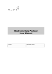
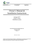
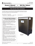
RDF
INSTALLATION INSTRUCTIONS
INSTALLATION
OPERATION
MAINTENANCE
09/08
READ AND SAVE THESE INSTRUCTIONS
For The Following Base Models:
RDF 8-8IP, RDF 8-8MAX, RDF 12-8IP, RDF 12-8
(See supplemental instructions for derived models, with duct
adapters, manifolds, etc., as appropriate for your particular model.)
CAUTION
For General Ventilating Use Only. Do
Not Use to Exhaust Hazardous or
Explosive Materials and Vapors.
WARNING
TO REDUCE THE RISK OF FIRE,
ELECTRIC SHOCK, OR INJURY
TO PERSONS, OBSERVE THE
FOLLOWING:
A. Use this unit only in the manner
intended by the manufacturer. If
you have any questions, contact the
manufacturer.
B. Before servicing or cleaning unit,
switch power off at service panel and
lock service panel to prevent power
from being switched on accidentally.
When the service disconnecting
means cannot be locked, securely
fasten a prominent warning device,
such as a tag to the service panel.
In addition to the following manufacturer’s
instructions, it is necessary to comply
with federal, state, and local government
codes. Your purchase of this American
ALDES ventilation system represents an
investment in the health and comfort of
the occupants, as well as an investment
in the protection of the building from the
damaging effects of excessive indoor
humidity.
This model of centrifugal fan is designed
for multiple purposes. It may be used
as an in-line rectangular duct fan (Model
RDF) or a manifolded, multi-port fan for
multiple exhaust or supply points. It
may be installed in a remote location
such as an attic space, mechanical room
or above a drop ceiling, in a closet or
laundry room, to provide quiet exhaust
of stale, humid, or otherwise polluted air
from bathrooms, the kitchen, laundry,
or storage rooms, via exhaust grilles
and ducting to the centrally located fan,
which is ducted to the outdoors. With
small return grilles in bedrooms and
other areas, and one duct connection
to the outdoors, as the BVS models, it
may also be used as a supply ventilator
or recirculating central ventilator for
the introduction of outdoor air, raising
the temperature of the fresh air by
mixing with recirculated indoor air.
When used with adjustable balancing
grilles or ALDES CAR, Constant Airflow
Regulators, and compatible roof/wall
caps, ducting, etc., the fan is the heart
of a complete pre-engineered ventilation
system.
SYSTEM DESIGN:
Satisfactory performance of a central
ventilation system requires the proper
integration of all the components:
•
Fan selection for airflow, pressure
and acoustic properties, vibration
characteristics and mounting method,
and mode of operation (continuous,
manually or automatically controlled)
•
Proper duct design for friction
losses, with compatible supply or
exhaust grilles (airflow and acoustic
properties of the supply/exhaust
grilles, and compatible wall/roof caps
•
Method of balancing airflows of
multi-point ventilation systems
•
Consideration for the potential of
condensation in the ducting or fan
housing (installation in an unheated
space)
Upon receipt, inspect the carton to insure
the fan has not been damaged in transit.
If damaged, it is the responsibility of the
recipient to file a damage claim with the
carrier. American ALDES Ventilation
Corporation is not responsible for
damage incurred during shipment.
Handle the unit with care to prevent
damage to the housing and other
components. Store the unit indoors if
possible. If outdoor storage is required,
protection against moisture and dirt is
necessary.
Unpack the unit, taking care to look
for any loose components among the
packing material. Make certain that the
fan housing and the blower is free of any
loose packing material or small parts.
If not removed before startup, damage
and injury may result from solid objects
discharged by the blower. Inspect for
damage, loose or missing parts.
Install the unit in its final location. The
fan may be installed in a mechanical
room, crawl space or attic. It is designed
to be placed on a flat surface, against
a wall or trusses, or suspended from
above. If set on a flat surface, vibration
isolation pads are recommended.
Mounting brackets with rubber grommets
are supplied to permit installation against
a vertical surface or from a ceiling above.
Alternatively, it may be suspended using
threaded rods or chains. At least 12
inches clearance is needed from the
access panel to permit servicing the
motor.
MOUNTING INSTRUCTIONS
(Differences in bracket type and
configuration may exist on some derived
models. Refer to supplement where
appropriate). Orient the fan so that the
access door can be opened for service.
Tools Required:
Power screwdriver with
No. 2 Philips bit.
Mounting brackets are supplied with
the fan. The brackets may be mounted
to the fan using the self-drilling screws
and rubber grommets provided, at the
locations indicated by dimple marks
on the side and bottom panels of the
fan. Pan head number 10 screws are
provided to attach the mounting bracket
to the building framing members. It may
be necessary to add additional framing
members to span wall studs. It is not
recommended to use drywall anchors
to support the fan. If installed against
a concrete or masonry wall, concrete
depending on local codes. If permitted
by code, insulated flexible ducting is
recommended for at least several feet on
each duct connection, to limit fan noise at
the outlet grilles. Ducting should conform
to NFPA 90A and meet the requirements
of Underwriters Laboratory as a Class O
or Class 1 duct to specification UL 181,
Standard for Factory-Made Air Ducts and
Duct Connectors. Metal ducting must
be sealed on both the end joints and
longitudinal seams to avoid duct leakage
and assure proper airflows at the grilles.
MAINTENANCE
Monthly:
Inspect and clean the exhaust grilles and
filters, if so equipped.
Annually:
To ensure the maximum efficiency of
the fan unit, is recommended to clean
the inside of the fan box as well as the
blower wheel.
FANS MAY BE MOUNTED VERTICALLY OR HORIZONTALLY
anchors are recommended. The rubber
grommets provide vibration isolation.
The brackets should be attached to the
fan first. Then install the wood screws at
the keyhole locations and install the fan.
The fan may also be mounted on a foam
rubber pad on a flat surface, such as an
attic floor.
COLD CLIMATE PRECAUTIONS
If installed in an unheated space, in
cold climates, there is a possibility
WARNING
TO REDUCE THE RISK OF
FIRE, ELECTRIC SHOCK,
OR INJURY TO PERSONS,
OBSERVE THE
FOLLOWING:
A. Installation Work and Electrical
Wiring Must Be Done By Qualified
Person(s) In Accordance With All
Applicable Codes And Standards,
Including Fire-Rated Construction.
B. Sufficient air is needed for proper
combustion and exhausting of
gases through the flue (chimney) of
fuel burning equipment to prevent
back drafting. Follow the heating
equipment manufacturer’s guideline
and safety standards such as those
published by the National Fire
Protection Association (NFPA), and
the American Society for Heating,
Refrigeration and Air Conditioning
Engineers (ASHRAE), and the local
code authorities.
C. When cutting or drilling into wall or
ceiling, do not damage electrical
wiring and other hidden utilities.
D. When used as exhaust fans,
ducted fans must always be vented
to the outdoors.
of condensation forming in the fan
housing or ducting components. A
backdraft damper installed at each
grille is very effective in reducing the
potential for condensation when the fan
is cycled on and off. Insulated ducting
must be used where exposed to cold
attic or crawl space temperatures, to
avoid condensation in the ducting.
Condensation can also be avoided by
continuous operation of the fan.
CAUTION:
Automatically operated device—to
reduce risk of injury disconnect from the
power supply before servicing.
DUCT CONNECTIONS
Ducting may be flexible or rigid,
DISASSEMBLY
Turn off all power to the unit. The blower
E. If this unit is to be installed over a
tub or shower, it must be marked as
appropriate for the application and be
connected to a GFCI (Ground Fault
Circuit Interrupter) - protected branch
circuit.
F.
NEVER place a switch where it can
be reached from a tub or shower.
ELECTRICAL
Provide disconnect switch in vicinity of fan, to
permit servicing fan, in accordance with NEC
and local codes.
Depending on the desired mode of operation,
switches may be simple on-off switches,
motor speed controls, timer switches, time
delay, time of day cycle timers, dehumidistats,
occupancy sensing controls, controllers,
etc., provided they are rated for motor duty
and meet the nameplate electrical ratings
of the motor. (Additional application wiring
diagrams are available illustrating a variety
of controls for use with RDF fans by calling
the factory at 1-800-255-7749.)
ELECTRICAL DATA
Base Model
Volts
Max Amps
Max Watts
RPM
RDF 8-8IP
RDF 8-8MAX
RDF 12-8IP
RDF 12-8
115
115
115
115
0.19
0.29
0.34
0.53
21
34
41
59
2500
3135
2200
2960
Field Wiring
Factory Wiring
Green/Yellow
White
Black
Field Wiring
Ground
Green/Yellow
White
Black
Neutral
Brown
115 V
RDF 8MAX
and RDF 12-8
Factory Wiring for
IP Protected Motors
White
Brown
Black
RDF 8-8 IP and
RDF 12-8 IP
For installations in which the fan is connected to a range hood, or if an exhaust grille connected to the fan
is located near the cooking surface as shown below, be sure to observe the following safety warnings:
WARNING
TO REDUCE THE RISK OF FIRE, USE ONLY
GALVANIZED STEEL DUCTWORK WHERE
REQUIRED TO USE METAL DUCT.
(Note: If the fan is not connected to a range
hood or a grille in the vicinity of the cooking
surface, other approved ducting may be used
as described in "Ducting" section of basic
instructions.)
WARNING
WARNING
TO REDUCE THE RISK OF A RANGE TOP
GREASE FIRE:
TO REDUCE THE RISK OF INJURY TO PERSONS IN THE EVENT OF A RANGE TOP
GREASE FIRE, OBSERVE THE FOLLOWING:
A.
Never leave surface units unattended
at high settings. Boilovers cause
smoking and greasy spillovers that
may ignite. Heat oils slowly on low or
medium settings.
A.
SMOTHER FLAMES with a close-fitting lid, cookie sheet, or metal tray, then turn off the
burner. BE CAREFUL TO PREVENT BURNS. If the flames do not go out immediately
EVACUATE AND CALL THE FIRE DEPARTMENT.
B.
NEVER PICK UP A FLAMING PAN - You may be burned.
Always turn hood ON when cooking at
high heat or flambeing food (i.e. Crepe
Suzette, Cherries Jubilee, Peppercorn
Beef Flambe).
C.
DO NOT USE WATER, including wet dishcloths or towels - a violent steam explosion
could result.
D.
Use an extinguisher ONLY if:
1. You know you have a Class ABC extinguisher, and you already know how
to operate it.
B.
C.
D.
Clean ventilating fans frequently.
Grease should not be allowed to
accumulate on fan or filter.
Use proper pan size. Always use
cookware appropriate for the size of
the surface element.
may be inspected and cleaned by
removing the two screws from the hinged
access panel. The blower assembly can
now be swung open for cleaning the
wheel.
DISCLAIMER:
IT IS THE RESPONSIBILITY
OF THE CONTRACTOR/
INSTALLER TO DETERMINE
THE SUITABILITY OF THIS
EQUIPMENT WITH RESPECT
TO THE POTENTIAL FOR
BACK DRAFTING NATURALLY
VENTED FLUE DEVICES
AND/OR AFFECTING RADON
ENTRY.
IMPACT OF EXHAUST FANS:
In especially tight homes heated with
naturally vented appliances, such as
gas, oil or wood-fired furnaces, boilers,
stoves or fireplaces, the exhaust system
may produce sufficient negative pressure
indoors to induce the backdrafting of
flue gases. This is a common, though
intermittent occurrence, with conventional
exhaust systems, such as vented kitchen
range hoods, clothes dryers, bath fans,
etc. In the case of continuous exhaust,
2. The fire is small and contained in the area where it started.
3. The fire department is being called.
4. You can fight the fire with your back to an exit.
a
Based on "Kitchen Firesafety Tips" published by NFPA.
BACKDRAFTING AND VENTILATION EQUIPMENT
even though often at lower flow rates, the
potential for backdrafting the flue of these
appliances does exist, and represents a
dangerous situation.
The International Fuel Gas Code,
Appendix D,- (http://www2.iccsafe.org/
states/Seattle/seattle_fuelgas/PDFs_
fuelgas/Appendix%20D.pdf) provides
a Recommended Procedure for Safety
Inspection of an Existing Appliance
Installation.
This procedure should be followed to
determine the presence of adequate
combustion air, while all exhaust fans
are operating at maximum speed, and all
doors and windows are closed.
In the event that backdrafting occurs,
steps must be taken to provide sufficient
combustion air to the furnace or boiler,
following the guidelines of the National
Fuel Gas Code and all state and local
codes.
MECHANICAL SUPPLY FANS:
Mechanical supply of outdoor air tends
to reduce the potential and frequency of
backdraft by reducing the contributing
negative pressures. However, because
of a multitude of factors, including the
wide range of exhausting appliances
that may be present, effects of wind and
building shape, presence of multiple
chimneys, building leakage and use of
operable windows, no one can assure
elimination of backdraft conditions
so long as atmospherically vented
combustion equipment is present in the
home.
American ALDES Ventilation Corporation
accepts no liability for backdraft
conditions resulting from negative
pressures. Nor does American ALDES
make representation that blending supply
ventilators are adequate to prevent such
occurrences.
SEE THE
THREE (3) YEAR WARRANTY
INFORMATION EXPLAINED ON THE
BACK PAGE.
NOTE:
THIS WARRANTY SUPERSEDES ALL
PRIOR WARRANTIES
REPLACEMENT PARTS LIST (BASE MODELS)
Motor
Part No
86 561
86 561
86 562
86 562
Model
RDF 8-8IP*
RDF 8-8 MAX
RDF 12-8IP*
RDF 12-8
Impeller
Dimensions
(mm)
133 x 42
133 x 45
180 x 35
180 x 35
Capacitor
Part No. Cap
86 172
4uF
86 172
4uF
86 174
10uF
86 170
5uF
*Designates Impedance Protection, with alternate wiring of capacitor across aux. winding of motor.
THREE (3) YEAR WARRANTY
THIS WARRANTY SUPERSEDES ALL PRIOR WARRANTIES
FOR FACTORY RETURN YOU MUST:
1) Have a Return Materials
Authorization (RMA) number. This
number may be obtained by calling:
AMERICAN ALDES
VENTILATION CORPORATION
PHONE: 1-800 255-7749.
Please have the Bill of Sale
available.
2) The RMA number must be clearly
displayed on the outside of the
carton, or delivery will be refused.
3) All product being returned must
be shipped prepaid and be
accompanied with a copy of the Bill
of Sale.
4) Product will be replaced/repaired and
shipped back to buyer. No credits
will be issued.
DURING THE FIRST THIRTY (30)
DAYS:
AMERICAN ALDES VENTILATION
CORPORATION will replace any
product which has a factory defect
in workmanship or material. Product
may be returned to either the point of
purchase or the AMERICAN ALDES
factory, together with Bill of Sale, for an
immediate replacement.
DURING THE FIRST THREE (3) YEARS
(excluding the above 30 day period):
AMERICAN ALDES VENTILATION
CORPORATION will replace any
product which has a factory defect in
workmanship or material. Product must
be returned to the AMERICAN ALDES
factory, together with the Bill of Sale , and
identified with an RMA number.
WARRANTY DOES NOT APPLY TO
THE FOLLOWING:
• Damages from shipping, either
concealed or visible. Claim must be
filed with the carrier.
• Damages resulting from improper
wiring or installation.
• Damages caused by acts of nature,
or resulting from improper consumer
procedures such as:
- Improper Maintenance
- Misuse, abuse, abnormal use, or
accident
- Incorrect electrical voltage or current
- Removal or alterations made on the
AMERICAN ALDES VENTILATION
CORPORATION label control
number or date of manufacture
•
Any other warranty, expressed,
written or implied, and to any
consequential or incidental damages,
loss of property, revenues, or profit,
or costs of removal, installation
or reinstallation, for any breach of
warranty.
WARRANTY VALIDATION
The end user must keep a copy of the Bill
of Sale to verify purchase date.
LIMITATIONS OF
WARRANTY AND LIABILITY
This warranty does not apply to any
AMERICAN ALDES product or part which
has failed as a result of faulty installation
or abuse, incorrect electrical connections
or alterations made by others, or use
under abnormal operating conditions or
misapplication of the product or parts.
We will not approve for payment any
repair not made by us or our authorized
agent without prior written consent.
The foregoing shall constitute our sole
and exclusive warranty and our sole
and exclusive liability, and is in lieu of
any other warranties, whether written,
oral, implied or statutory. There are no
warranties which extend beyond the
description on the page hereof. In no
event, whether as a result of breach
of contract, or warranty or alleged
negligence, defect, incorrect advice or
other causes, shall AMERICAN ALDES
be liable for special or consequential
damages, including but not limited to,
loss of profits or revenue, loss of use
of equipment or any other associated
equipment, cost of substitute equipment,
facilities or services, downtime costs,
or claims of customers of purchases for
such damages. AMERICAN ALDES
neither assumes or authorizes any
person to assume for it any other liability
in connection with the sale of its products
or parts. Some jurisdictions do not allow
the exclusion or limitation of incidental or
consequential damages, so the above
limitations and exclusions may not apply
to you.
BRADENTON, FL 34203
P:
941.351.3441
F:
941.351.3442
E:
[email protected]
www.americanaldes.com
09/08
MODEL MPVS 100 AND 120
INSTALLATION
OPERATION
MAINTENANCE
INSTALLATION INSTRUCTIONS
(Supplement to RDF 09/08)
02/09
General: MPVS Series multi-port
ventilators are highly versatile continuous
duty rated fan units for residential and
light commercial applications, and meet
ENERGY STAR efficiency criteria for
low energy consumption. The most
popular use is central continuous exhaust
ventilation of bathrooms, kitchens, laundry
rooms, and other rooms where humidity
is a controlling factor, since the fan has a
single exhaust discharge duct directly to
the outdoors.
The principle advantage of the MPVS
central exhaust system is the assurance
of controlled indoor air quality ventilation
and the elimination of standard noisy bath
fans, with the obvious benefits of reduced
penetrations to the exterior of the building.
With the increased tightness of construction
for energy efficient buildings, there is a
growing need of mechanical ventilation for
indoor air quality. These fans are designed
to serve this purpose as well, by providing
effective bathroom ventilation, with the
ability to run intermittently or continuously
as needed. The quiet, energy efficient
permanent split capacitor external rotor
motor has permanently sealed bearings
that provide many years of maintenancefree performance.
DROP DOWN
HINGED
ACCESS
PANEL FOR
SERVICE AND
INSPECTION
DIMENSIONS:
MPVS 100 and 120
Duct Configuration(s) 313, 323, and 333
Construction: The MPVS fan is
constructed of heavy gauge galvanized
steel to prevent corrosion caused by
moisture. The cabinet is internally lined
with UL rated, acoustic closed-cell foam
vapor barrier insulation. This allows
installation directly above living spaces,
or in unheated plenum spaces without
concern for noise or condensation.
Fan and Motor: The fan motor is an energy
efficient permanent split capacitor type,
of external rotor design. Totally sealed to
protect against moisture and contaminants,
it is approved for use to remove steam
and moisture in kitchen and bath areas.
The motor incorporates permanently
lubricated sealed bearings and automatic
reset thermal overload protection. It is
designed and certified for continuous duty
or intermittent operation.
The fan uses a backward inclined
impeller design that minimizes dust from
collecting on the blades and affecting
airflow performance. Each fan is statically
and dynamically balanced in the factory
to eliminate vibration and ensure quiet
ELECTRICAL AND AIRFLOW PERFORMANCE
Model
Nominal
RPM
HP
MPVS-100
2980
0.03
MPVS-120
3135
0.05
CFM vs. Static Pressure*
Volts
Watts at
.2" Ps
MAX.
AMPS
0"
.2"
.4"
.6"
.8"
120
22
0.19
108
88
68
48
25
120
38
0.29
143
128
112
95
74
*Certified airflow rating at 0.2" w.g. is derated from actual test results per HVI Certification
procedure 920.
operation. The entire motor and fan
assembly is mounted on a drop-down
hinged access panel for service and
inspection, and can be removed from
the fan without disassembly of the
ducting connections.
MOUNTING BRACKET
LOCATIONS
Controls: The fans can be operated
manually, or automatically by a
programmable timer or dehumidistat
and may also be operated in
conjunction with a variable speed
control.
Locating and Installing the Fan:
The compact dimensions and
versatile mounting options permit
installation above drop ceilings,
between ceiling joists, or within a
small soffit location. The fan can
be installed either horizontally or
vertically.
Airflow Balancing: The flow
rates are automatically set with
preset ALDES Constant Airflow
Regulators.
A passively controlled element in
each duct run inflates or deflates
automatically in response to system
pressure to maintain constant
airflow.
ELECTRICAL DATA
MPVS 100 / 120
120 V, 60 Hz., .19/.29 amp.,
22/38 W Max., 2980 / 3135 RPM
Above ratings are intended for sizing
electrical wring only. Actual consumption
will be lower.
TABLE OF AIRFLOWS AND DUCT LENGHTS*
3" INTAKE DUCT TO FAN
Recommended
Max. Duct Length from
Grille to Fan (ft.)
TOTAL
EXHAUST
RATE CFM
FAN DISCHARGE DUCT
Assumes low pressure drop
vent cap
AIRFLOW
CFM
4" SMOOTH
4" FLEXIBLE
SMOOTH
FLEXIBLE
60
40 ft
20 ft
10
225
180
75
25 ft
15 ft
20
65
50
90
18 ft
12 ft
30
30
25
100
15 ft
9 ft
40**
20
15
120
11 ft
8 ft
50**
10
10
135
8 ft
6 ft
FOR EACH
ELBOW
DEDUCT
3" Diameter
= 3 Feet
*This table should only be used as a general guide. Actual duct length allowances may be longer on some models. Contact the factory for
assistance. **CAR Flow Regulators not available over 35 cfm. NOTE: If longer duct runs are required than permitted in the table above, use smooth
ducting and/or increase the diameter.
BRADENTON, FL 34203
P:
941.351.3441
F:
941.351.3442
E:
[email protected]
www.americanaldes.com
02/09