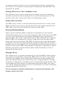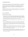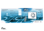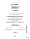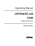
1
Build Better To Last Longer
Residential
Central Heat Recovery Ventilator
User Manual
Superventor Series
Model
SHRV 100T/SHRV124T
TOP CONNECT
Installation Information
Installing Contractor
Telephone Number
Unit Model Number
Unit Serial Number
Installation Date
Summeraire Mfg.
Peterborough, Ontario,
Canada, K9J 6X6
INTRODUCTION
This Manual provides you with an introduction to the principles of Heat
Recovery Ventilators (HRV), the operation and maintenance of your unit,
guidelines to troubleshooting minor problems as they may occur and an outline
of your warranty. Each of these areas are described fully under their specific
headings as set out in the Table Of Contents.
To obtain information relating to the installation, technical specifications and
exploded parts diagram for your unit, please refer to the Installation Manual.
We congratulate you on your purchase of a Summeraire unit and thank-you for
choosing SUMMERAIRE. We are confident that your Summeraire HRV will
provide many years of fresh air comfort to your family.
Table of Contents
1. Description of Your Unit and its Benefits......................................................... 3
2. Suggested Operating Instructions..................................................................... 4
3. How to Operate Unit and Related Controls...................................................... 6
4. Optional Controls.............................................................................................. 9
5. Basic Components of your HRV..................................................................... 14
6. Maintenance.................................................................................................... 16
7. Troubleshooting.............................................................................................. 19
8. Warranty.......................................................................................................... 21
1. DESCRIPTION OF YOUR UNIT and IT’S BENEFITS
Since the energy crisis in the early 1970’s, governments and the building
community have sponsored many programs and changed codes to foster reduced
energy requirements and create energy costs savings for the consumers. Each of
these efforts, while improving the energy efficiency of our homes and buildings,
has resulted in the loss of natural ventilation and trapped excess humidity and
pollutants indoors.
It is due to this air tightness that your dwelling or place of business will incur
humidity from everyday activities such as cooking, bathing, washing, indoor
drying of clothes and normal breathing and perspiration. Pollutants such as
smoke from cooking and fireplaces or wood burning stoves, dust, pollens,
airborne viruses and molds and radon gas can also be trapped in your residence.
Your SUMMERAIRE Heat Recovery Ventilator (HRV) is designed to resolve
these problems by providing fresh air into your home or building while
exhausting an equal amount of stale, humid air. This “exchange” process enables
you to remove undesirable pollutants continuously as well as excess humidity
during the heating season. The advantage offered by your HRV is that it transfers
the energy from your exhausted (inside conditioned air) to temper the incoming
fresh air system.
3
2. SUGGESTED OPERATING INSTRUCTIONS
Anytime the HRV is powered on allow 20 seconds for the main
control to reset prior to making any operational selections.
Heating Season
Turn HRV ON, fan speed will cycle to previously select mode of operation.
Continuous low speed ventilation is recommended to ensure that fresh air is
available to building occupants.
If your home feels too humid or if you have water condensation on the windows,
rotate the built-in dehumidistat Dial (left side of HRV). Set dehumidistat control
between 30-40% humidity.
If your home feels to dry: rotate dehumidistat Dial (left side of HRV) slowly in
a COUNTER-CLOCKWISE direction in 5 point increments and allow HRV to
run in this position for 24 hours. If symptom continues, repeat this step. Also, if
there is a humidifier installed, check to make sure it is working properly.
If a higher rate of continuous ventilation is desired: Press the SELECT button
(located at left hand side of HRV) once to change to the next run speed.
If HRV continuous ventilation is not desired (not recommended), press the
SELECT button until LED at AUTO/OFF is illuminated. HRV will not run
unless a wall control is activated. Remote Touch Pad will activate 20/40/60
minutes of high-speed ventilation and then the HRV will return to AUTO/OFF.
Dehumidistat activation results in high-speed ventilation until humidity level of
indoor air is less than the dehumidistat setting, then the HRV will then return to
AUTO/OFF.
Note: If your house is too dry, it’s best to install a humidifier rather than to turn
the HRV off.
4
Air Conditioning Season
Continuous ventilation is recommended when the house is being heated or
cooled, anytime windows are closed. For summertime operation of the HRV,
turn the dehumidistat setting counter clockwise to off (80%), set run speed to
LOW. Changing the stale indoor air with fresh outdoor air is just as important in
the cooling season as it is in the heating season!
If no HRV ventilation is desired (not recommended): Press SELECT button until
LED at AUTO/OFF is illuminated. HRV will not run unless a Remote Touch Pad
is activated. Wall control activation results in 20/40/60 minutes of high-speed
ventilation. After 20/40/60 cycle the HRV will return to AUTO/OFF. Continuous
low speed HRV ventilation is recommended throughout the year.
REMOTE CONTROL DEVICES
SCOUT (Remotely Located)
Fan speed selection, Auto/Off and system Off maybe selected. The HRV defrost
cycle is also displayed when active.
20/40/60 minute Touch Pad;
Touch Pads switch the HRV to high speed for 20/40 or 60 minutes. Each touch
pad station will illuminate while the HRV is running at high speed.
Remote wall dehumidistat;
When using a remote wall dehumidistat, set the HRV built-in dehumidistat to
OFF. Adjust humidity level from the wall dehumidistat only.
WATCHMAN and SENTINEL wall controls;
When using these wall controls, set the HRV built-in dehumidistat to off.
Operate the HRV as outlined above, but from the wall controls. Refer to specific
control operation guides in this manual for further information.
5
3. HOW TO OPERATE UNIT and RELATED CONTROLS
Anytime the HRV is powered on allow 20 seconds for the main
control to reset prior to making any operational selections.
To realize the full benefit of your HRV, it should be operated continuously to
control humidity and supply fresh outdoor air.
Continuous ventilation of your home is very important, and as the need arises
to introduce higher levels of ventilation, you can select increased fan speeds at
the HRV, or if installed, at remote devices such as; TOUCH PAD TIMERS, or
SCOUT, WATCHMAN or SENTINEL controls.
This section reviews the basic operation of your HRV and related controls to
maximize your home comfort.
All units are equipped with a Safety door switch, built in On/Off switch,
Variable Speed Fan control, Dehumidistat control and have automatic damper
defrost control, which is preset at the factory.
1
2
3
4
1 - Internal Dehumidistat
2 - Power On/Off Switch
3 - Option Select Button and Status Display Panel
4 - Summer / Winter Switch
6
On/Off Switch
The ON/OFF switch supplies and disconnects power to the HRV control board.
When positioned in the ON position, this switch will illuminate. The switch will
not illuminate if the power supply is disconnected or the switch is turned to the
OFF position.
Option Select Button
By depressing the SELECT button momentarily, you can select low, medium or
high ventilation fan speeds, as well as the AUTO/OFF or SYSTEM OFF modes.
The selection will be indicated by the illumination of the respective LED on the
HRV display panel.
Auto/Off
When this mode of operation is selected, the HRV ventilator fan will be turned
off until activated by the internal dehumidistat or an optional external control
such as a Wall Mount Dehumidistat, Wall Switch, Touch Pad Timer, Scout,
Watchman or Sentinel control. This selection is displayed by the continuous
illumination of the Auto/Off LED on the HRV, SCOUT, WATCHMAN and
SENTINEL controls. When the fan is activated automatically or manually at
a Touch Pad, it will be indicated by the flashing On and Off of the High-speed
indicator on the control panels.
High Speed Flashing
When the internal dehumidistat or an external control has activated the HRV
to high speed, the High Speed LED light will illuminate and flash. If you have
already selected one of the ventilation speeds as discussed in the previous
section “Option Select Button”, and the High Speed has been activated, then
you will see both the continuously lit LED for the fan speed selection and the
high speed LED flashing. Once the device initiating the high speed cycle has
been satisfied, the HRV control fan will reset to the pre-selected mode and the
flashing High Speed LED will turn off.
Summer / Winter Switch
This switch must be positioned in the summer position when the optional
summer core is installed in the HRV. This will cause the HRV to shut down
should the air temperature entering the HRV fall below -15°C (5°F). This
prevents permanent damage to the core. Position this switch to winter when
the winter core is used to ensure correct operation during colder periods.
7
Status Display Indicator Lights
The LED indicator lights illuminate to indicate the current active mode of
operation. The defrost indicator will illuminate when the HRV cycles into the
automatic defrost cycle; this occurs at a predetermined cycle time whenever the
outside air stream entering the HRV is colder than -3°C (26°F).
Defrost Cycle
Your HRV is equipped with electronically controlled damper defrost. When
the outdoor temperature entering the HRV drops below -3°C (26°F) the defrost
timer is activated. After approximately 30 minutes of ventilation (during which
time the core unit may experience some frost build-up during the heat recovery
process) the timer activates the damper door mechanism which closes off the
fresh air supply port, opens the defrost port and the defrost led illuminates.
After approximately 5 minutes of defrosting the recovery core, the damper door
reverses direction and reopens the fresh air port and the unit returns to normal
operation and the defrost led turns off. The cycle will repeat itself until the
outdoor temperature entering the HRV rises above -3°C (26°F).
Internal Dehumidistat
This control regulates the desired amount of humidity in your home during
the heating season. By simply adjusting the rotary knob on the HRV, varied
levels of relative humidity can be selected.During the colder months of winter,
the Internal Dehumidistat should be set to an industry recommended comfort
range of 30% to 40% relative humidity (R.H.). If the house feels too dry, then
adjust the setting higher and if too damp, then adjust the setting lower.During
these colder months, the Internal Dehumidistat should be set lower if excessive
moisture develops on the windows. In the warmer months, when the outdoor
humidity is equal to or greater than the indoor humidity, the dehumidistat should
be turned to the OFF position.
8
OPTIONAL CONTROLS
20 Minute Remote Timer Touch Pad
Model ECPBT
This 20-Minute Touch Pad MUST be connected to the “CT”
terminals on the HRV exterior. This control will not function if
connected PBT connection points. Install using 18/2-thermostat
wire. Maximum number of ECPBT controls per HRV is eight.
Maximum cumulative lead length is 2000 lineal feet. Touch
pads are typically installed where 20 minutes of high speed
ventilation may be desired.
Once activated by a momentary push, approximately three
seconds, of the SELECT button on the Touch Pad the HRV
is switched to high speed ventilation and the Touch Pad LED
will illuminate. The HRV will reset to the previously selected
mode of operation once the 20 minutes have expired. To cancel
the selection, depress the SELECT button on the 20-minute
Touch Pad for a minimum of 3 seconds. The selection can
also be cancelled at any other optional control by momentarily
depressing the SELECT button.
NOTE: This control will not respond while a crank timer is
operational.
9
Remote Timer Touch Pad - Model PBT
Timer Touch Pads are typically installed in any room
where 20/40 or 60 minutes of high-speed ventilation
may be desired, i.e. bathrooms and/or kitchens. Once
activated by a momentary push, these buttons illuminate
to indicate high speed activation. If more than one touch
pad is installed in the system then all will illuminate upon
activation until the timed sequence has expired. To cancel
a selection simply continue to push the select button
until it turns off. The display LEDS on the touch pad will
illuminate to represent the time remaining.
Wall Mount Dehumidistat - Model SRDEH
This control is typically installed in an area of the home
where humidity may require automatic monitoring. This
could be a central location (i.e. near furnace thermostat)
or in a specific room (i.e. kitchen, laundry etc.).
Scout Control
This control is detachable from the HRV to provide a
remote control operation of the HRV. Once removed from
the HRV one can only turn the power off at the HRV. By
positioning the Scout remotely to the HRV, you can adjust
fans speeds, select auto/off, intermittent or turn the main
HRV control Off. When the HRV has been turned off
using the Scout, power still remains on at the HRV on/off
switch however all external controls will not function.
Intermittent- In this mode the ventilation fan will run for
20 minutes and turns off for 40 minutes. This cycle will
continue until cancelled. External devices are active.
10
WATCHMAN CONTROL
The WATCHMAN is an intermediate remote
control. It permits the following function
selections;
SYSTEM OFF- In this position all internal and
external controls are disabled. Power remains on
at the HRV.
FAN SPEED- Low Medium or HIGH can be
selected.
INTERMITTENT- In this mode the ventilation
fan will run for 40 minutes and turns off for 20
minutes. This cycle will continue until cancelled.
External devices are active.
AUTO/OFF-In this mode the ventilation fan
remains off until activated by either the internal
dehumidistat or an external control such as a
Touch Pad or Dehumidistat. During the off mode
the cold air port in the HRV is closed.
RELATIVE HUMIDITY- By rotating the control
dial you can select desired levels of indoor
humidity. Humidity reduction will only occur
during the heating season. Should the set point
be below the indoor relative humidity the HRV
will automatically switch to high speed (provided
that the active mode selected permits the remote
device to be active).
SENTINEL CONTROL
The SENTINEL control is the deluxe control
using a digital LCD display to indicate HRV
status. The top line of the display indicates the
current mode of operation, the lower left side
indicates the ventilation fan status and the lower
right hand side indicates the current relative
humidity.The following option selections are
available in addition to those offered by the
WATCHMAN;
TIMED HIGH SPEED- 20/40 or 60 minutes
of high speed ventilation can be selected or
cancelled.
FILTRATION- In this mode the HRV fan runs
continuously recirculating indoor air through the
11
HRV filters. During this cycle the outdoor cold air port is closed. No fresh air is
introduced.
CLEAN FILTER INDICATOR- Twice annually the control will display on the
LCD the need to clean the filters and core. Refer to the maintenance for the
method advised.
To make a selection, depress the left button identified as SELECT/SET. As you
push this button you will see the display change to the various operating options
ie. VENTILATION, SET FAN TIMER, SET FAN SPEED, SET HUMIDITY
etc.. Once you have selected the desired option, press the CHANGE button
on the right to make a change, then press the SELECT/SET button on the left
to save and initiate the selection. To confirm that the selection was made, the
display will momentarily read “SET UP CHANGED”, it will then default to
the selected mode of operation. Note that fan speed must be selected prior
to selecting the FILTRATION mode. Failure to select the fan speed first
will result in the fan defaulting to the previous mode of operation during the
FILTRATION cycle.
SCOUT / WATCHMAN Indications
MODE
SCOUT
WATCHMAN
Intermittent Fan Off
Auto Off, Blink
Intermittent LED ON, Blink Auto Off
Intermittent Fan Hi
High, Blink
Intermittent LED ON. Blink Hi
Filtration
Default fan speed, Slow Blink
Default fan speed, Slow Blink
Summer Switch
on Temp <5deg°F
System Off, Blink
System Off, Blink
Filtered
Air Out
Air In
Filtration
12
OPTIONAL SUMMER CORE DEFROST SCHEDULE
When using the summer core, the Summer/Winter switch at the left hand side of
the HRV must be set to summer. When the summer switch is ON the following
defrost schedule is followed for temperatures below -5.5°C (22°F) and below
-15°C (5°F) .
While the temperature is above -5.5°C (22°F) the system operates normally.
While the temperature is below -5.5°C (22°F) and above -15°C (5°F) , the
system will run a defrost cycle (fan high) for 6 minutes. At the end of the defrost
period the system will return to the previously selected mode. After 32 minutes,
if the temperature is below -5.5°C (22°F) but above -15°C (5°F), this defrost
cycle will be repeated.
If the temperature is below -15°C (5°F) , the system will run the 6 minutes
defrost period and then switch to fans off. After 54 minutes, if the temperature is
below -15°C (5°F) , the 6 minute/54 minute schedule will be repeated. If the
temperature remains below -15°C (5°F) for four cycles of 6-54 the system go
to the System Off mode. The system Off LEDs will blink and the will display
INSTALL WINTER CORE. If the temperature remains above -15°C (5°F) for
more than an hour, the cycle count will be reset to zero. This permits the system
to continue to operate if the temperature is only below -15°C (5°F) for less than
four hours.
NOTE THAT THE SUMMER CORE WILL BE PERMANENTLY DAMAGED
SHOULD IT BE EXPOSED TO TEMPERATURES BELOW ---- 15°C (5°F) .
When the summer core is installed in the HRV the select switch on the left
hand side must be set to summer. Failure to do so will result in permanent
core damage.
When using the winter core, this select switch must be set to winter to ensure
proper HRV operation during the colder periods.
13
4. BASIC COMPONENTS OF YOUR HRV
3
4
5
6
2
1
17
16
15
14
7
13
8
12
9
11
10
1 - ON/OFF Switch
2 - Dehumidistat
3 - Door Safty Switch
4 - Air Filter
5 - Heat Recovery Core
6 - Door Hinge
7 - Damper Motor
13 - Supply Fan Panel Access
8 - Damper Door
Screw (8)
9 - Exhuat Fan
14 - Summer/Winter Switch
10 - Door Latch
15 - Terminal Block
11 - Door Latch
16 - Option Select Switch
12 - Condensate Tray 17 - Status Display
Do not attempt to operate damper door manually.
To do so will result in damper motor failure.
Heat Recovery Core (winter core)
One of the most important components of your HRV is it’s Heat Recovery Core. In
the winter months, during the heating season, this plated Core recovers energy from
the stale humid air being exhausted and transfers this energy to temper the incoming
colder fresh air. This process also reduces indoor relative humidity during this time.
In the summer months, during the air conditioning season, the incoming fresh
air is conditioned as it passes through the Core. This occurs as the conditioned
indoor air being exhausted cools the Core and the incoming fresh air.
The Winter Core is designed of an impenetrable polymer material so that the
14
air streams remain separate (no cross-contamination) thereby ensuring that
the fresh air is not exposed to the potential contaminants and humidity in the
exhausted air stream.
Energy Recovery Core (summer core)
The Summer Core not only conditions the incoming air but also transfers
moisture contained in the incoming fresh air to the exhausting stale air. This
benefit reduces the cooling load on the air conditioning system.
Safety Door Switch
The HRV safety switch is activated when the main front door is fully closed.
When the front access door is opened electrical power is disconnected to the
HRV main control board disabling all functions of the HRV.
Internal Dehumidistat
Indoor relative humidity (RH) is monitored continuously by the internal
dehumidistat during fan on cycles. By rotating the dial on the front of the HRV
you can select the desired level of indoor humidity. Range of operation is
approximately 20% to 80%. Should the level of RH exceed the level selected
then the HRV will automatically switch to high speed until the indoor RH
drops below the level selected. The HRV fan must be on for the dehumidistat
to function correctly. Note that during the summer months when the outdoor
humidity may be at elevated levels, all dehumidistats must be turned to the off
position to prevent the HRV from running on high speed continuously. Indoor
humidity will only be reduced when outdoor relative humidity is lower ie.
during the heating season.
Damper Door
This damper door is operated automatically by the main HRV control should
the outdoor air temperature entering the HRV fall below 26°F (-3°C). When
activated, this damper closes off the stale exhaust port within the HRV and
opens the internal defrost port. The defrost cycle is approximately 5 minutes
in duration, followed by a ventilation cycle of approximately 30 minutes. This
cycle repeats until the outdoor air temperature entering the HRV rises above
-3°C (26°F). During the defrost cycle it is not unusual to see water condensate
dripping through the drain lines.
Do not attempt to reposition this damper, as permanent damage to the
damper motor will result.
15
5. MAINTENANCE
In addition to the maintenance procedure outlined below, we recommend that
you inspect the exterior hoods on your unit every month. This is to ensure
that your exhaust and fresh air supply ports are not restricted by debris (i.e.
cottonwood, leaves, grass, snow or frost (ice) buildup on the mesh cover(s).
Restriction of these ports will cause the unit to work inefficiently and
malfunction.
Caution: Unplug the unit prior to performing maintenance or working inside
the unit. Please do not attempt to reposition the damper door as this will cause
permanent damage to the motor.
Every Six Months
Disconnect the power supply
1. Unlatch the door latches at the bottom of the front door panel and gently
raise the door to a level position while securely holding the door panel in
place (apply pressure to the right) (CAUTION - Door can slip off hinges).
Once open, hold the access door securely and slide it to the right. This will
disengage the upper hinges allowing the door to be removed.
2. Remove the filters as shown and wash in warm, soapy water, rinse, let dry
and replace.
3. Remove the HRV Winter Core by sliding it out evenly along the channel
tracks, wash in warm soapy water, rinse, let dry and replace. To replace
properly, slide the core back into the tracks with the label attached to the
core indicating the top upright position of the Core, in the most top upright
location.
Caution: Do not expose the Summer Core to water. To do so will result in
permanent damage. Simply vacuum the surfaces of the summer core lightly
with a brush attachment. We suggest that you wear gloves when handling
the Cores as some edges may be sharp.
4. Clean and inspect the condensate trays by wiping with a damp cloth.
Observe the tray outlets and the drain hose to ensure they are clear of debris.
If debris is present flush out the drain system with warm soapy water or
have the hose replaced.
16
Every Three Years - Clean Fan Blades
Fan blades can accumulate dust and dirt creating reduced airflow and potential
imbalance of the blades. It is also our recommendation that you consider
having a qualified service contractor perform your Fan Blade maintenance.
Fan Maintenance
3
2
Fig.1
1
CAUTION: Internal HRV components can have sharp metal edges Recommend wearing gloves.
17
Refer to Fig.1 Page 17
1. As described in the prior section, unplug unit and open access door
(swings up).
2. Remove dehumidistat knob (3) by gently pulling it forward.
3. Remove wire leads from terminal strip by loosening securing screws in front
of terminal strip. Be sure to identify leads and location prior to removing to
ensure they are returned to the correct location.
4. Remove front cover securing screws (1) and front cover (2).
5. Using a small brush (i.e. toothbrush), clean the wheel blades. Caution must be
exercised not to disturb the balancing weights on the wheel blades.
6. Reassemble.
7. Reconnect the power supply to the fan motor.
18
6. TROUBLE SHOOTING
Control Functions
Symptom
Possible Cause
Possible Solution
Nothing works
Front access door safety switch
Ensure that HRV is plugged in
Front access door safety switch
Unlatch door, inspect safety switch
Lack of power.
Defective component
Ensure that outlet in use is powered
Contact your installer
HRV front panel
On/Off switch
illuminates but
fan is not running
Mode of operation selected set
to “Auto Off”
Select a different operation mode at
HRV or remote device
HRV status panel
flashing HIGH
Continuously
HRV internal dehumidistat set
too low.
Adjust dehumidistat RH setting to a
higher setting.
Remote push button activated.
Check to see if a push button has
been activated.
Defective component.
External dehumidistat set too
low.
Defective dehumidistat.
Contact your installer
Adjust external dehumidistat set point
higher.
Contact your installer.
Defective PC board.
Contact your installer.
Operational Functions
Symptom
Possible Cause
Possible Solution
HRV is operating
but little or no air
flow is present.
Air stream blockage
Check outside weather hoods for
blockages such as snow, grass,
insects, cottonwood.
Dirty air filters or heat
exchanger Core.
Inspect and clean air filters and core.
Heat exchanger core frozen
solid.
Defective component.
Open HRV access door and defrost
Core. Contact your installer. Have
unit inspected for defective sensors,
check system balancing.
Contact your installer.
19
Control Functions
Symptom
Possible Cause
Possible Solution
Poor air quality
excess moisture
on windows.
HRV turned off
Adjust ventilation rate higher and
HRV running on too low a speed monitor conditions overnight.
Adjust further if necessary.
If HRV is connected to furnace
ductwork (both exhaust and
supply)
Temporary conditions causing
effect.
Ensure that furnace is turned on to
circulate air.
Activate to high speed at push button
or Airmonitor.
Indoor air temperature too low.
Keep temperature above 18°C (64°F)
Excessive humidity conditions
within home. Turn down
internal or remote dehumidistat.
Consider source such as improper
foundation drainage, moisture
intrusion into exterior walls, moisture
generation, excessive moisture
conditions.
New wet construction.
Indoor air
considered too
dry
HRV speed selection too high
for conditions.
Set to a lower speed.
Check dehumidistat settings. Adjust
higher. Set to intermittent mode
of operation. Temporarily use a
humidifier.
Excessive frost
build up on ducts
connected to
HRV.
Supply air too
cold.
Extreme outdoor air
temperatures.
Operate HRV on intermittent.
Operate HRV at a lower ventilation
rate.
Have a duct heater installed.
Imbalance in air flow streams.
Defective defrost system.
Defective Vapor Barrier.
20
Have the system’s balancing checked.
Have the defrost system checked.
Inspect duct connections at collars,
look for vapor tear and repair.
7. WARRANTY
HRV Unit
Summeraire Mfg. warrants the entire Heat Recovery Ventilator to the original
purchaser should it prove to be defective by reason of defective material and
or faulty workmanship with in two (2) years of the purchase date. Extended
warranties are offered for the “Core” and “Electrical components” as outlined
below.
Core
Summeraire Mfg. warrants the “Core” of the Heat Recovery Ventilator to the
original purchaser if the core has become defective by reason of defective
material and/or faulty workmanship. This warranty applies to the original
purchaser of the Heat Recovery Ventilator for as long as they own the dwelling.
Electrical Components
Summeraire Mfg. warrants the “Electrical components” of the Heat Recovery
Ventilator to the original purchaser if any of the electrical components have
become faulty by reason of defective material and/or faulty workmanship.
This warranty applies to the original purchaser of the Heat Recovery Ventilator
for a period of five (5) years from the date of purchase as long as they own the
dwelling.
21
General Provisions
Summeraire Mfg. will supply a replacement HRV unit or component as
prescribed in the forgoing section, F.O.B. Peterborough, Ontario, Canada.
Replacement units and/ or components are warranted for the remainder of the
original warranty period.
This warranty does not cover defects caused by: modifications, alteration,
abuse to, or misuse of the product or it’s operation in a manner contrary to the
instructions included with the unit at the time of shipment, or failure to perform
maintenance as detailed in aforementioned instructions.
This warranty expressly supersedes all other warranties and obligations of
Summeraire Mfg.. No person has authority to alter or modify the terms of this
warranty in any matter.
This warranty does not include any freight, labour, including diagnostic labour,
or sales tax that might be incurred by the purchaser if a unit and or parts require
replacement.
Under no circumstances shall Summeraire Mfg. be liable to the purchaser or any
other person(s) for any consequential damages, whether arising out of breach of
warranty, breach of contract, negligence or otherwise.
Keep your warranty at work for you. Please complete and mail your Warranty
Registration Card to Summeraire Mfg., 2040 Fisher Drive, Peterborough,
Ontario, Canada, K9J 6X6 to register this warranty.
22
Notes:
23
Summeraire Mfg.
2040 Fisher Drive,
Peterborough, Ontario
Canada, K9J 6X6
X-100T-124T-USMAN-EN-REV2