1
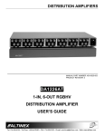
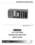
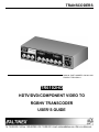
TRANSCODERS
MANUAL PART NUMBER: 400-0031-003
PRODUCT REVISION: 1
TR6102HD
HDTV/DVD/COMPONENT VIDEO TO
RGBHV TRANSCODER
USER’S GUIDE
TRANSCODERS
INTRODUCTION
TABLE OF CONTENTS
Page
Thank you for your purchase of the TR6102HD
Transcoder. We are certain that you will find it a
reliable and useful product.
PRECAUTIONS / SAFETY WARNINGS ...............2
GENERAL ..........................................................2
Superior performance for the right price backed by
solid technical and customer support is what we
have to offer.
RACK MOUNT SAFETY GUIDELINES ..............2
INSTALLATION..................................................2
CLEANING .........................................................2
The product you are holding in your hands is
designed using state-of-the-art technology and is
superior to anything available on the market. You
will find this and our other products reliable, long
lasting, and simple to operate.
FCC / CE NOTICE .............................................2
ABOUT YOUR TRANSCODER .............................3
TECHNICAL SPECIFICATIONS............................3
We are committed to providing our customers with
solutions to the most demanding audio-visual
installations at very competitive pricing.
APPLICATION DIAGRAM .....................................4
INSTALLING YOUR TRANSCODER.....................4
OPERATION .........................................................4
We appreciate your selection of our products and
are confident that you will join the ranks of our
many satisfied customers throughout the world.
RGB OUTPUT....................................................5
POWER .............................................................5
CABLE REQUIREMENTS ..................................5
ACCESSORIES.....................................................5
This manual covers:
ALTINEX POLICY .................................................6
TR6102HD – HDTV/DVD Component video to
RGBHV Transcoder
LIMITED WARRANTY........................................6
RETURN POLICY ..............................................6
CONTACT INFORMATION ................................6
1
TRANSCODERS
1
•
Please read this manual carefully before using your
TR6102HD Transcoder. Keep this manual handy
for future reference. These safety instructions are
to ensure the long life of your TR6102HD and to
prevent fire and shock hazard. Please read them
carefully and heed all warnings.
Do not place heavy objects on top of the
TR6102HD. If the TR6102HD is to be mounted
to a table or wall, use only Altinex made
mounting accessories, such as the mount minibrackets DA1295SX and cables for optimum
setup.
•
To turn off the main power, be sure to remove
the cord from the power outlet. The power outlet
socket should be installed as close to the
equipment as possible, and should be easily
accessible.
•
Do not pull the power cord or any cable that is
attached to the TR6102HD Transcoder.
•
If the TR6102HD Transcoder is not used for an
extended period, disconnect the power cord
from the power outlet.
PRECAUTIONS / SAFETY WARNINGS
1.1 GENERAL
•
Unauthorized personnel shall not open the unit
since there are high-voltage components inside.
•
Qualified Altinex service personnel, or their
authorized representatives must perform all
service.
1.2 SAFETY GUIDELINES FOR THE RACKMOUNTING OF THE TR6102HD
•
Maximum operating ambient temperature is 35
(degrees C).
•
Never restrict the airflow through the devices’
fan or vents.
•
When installing equipment into a rack,
distribute the units evenly. Otherwise,
hazardous conditions may be created by an
uneven weight distribution.
•
Connect the unit to a properly rated supply
circuit.
•
Reliable Earthing (Grounding) of RackMounted Equipment should be maintained.
1.4 CLEANING
•
1.5 FCC / CE NOTICE
•
This device complies with part 15 of the FCC
Rules. Operation is subject to the following two
conditions: (1) This device may not cause
harmful interference, and (2) this device must
accept any interference received, including
interference that may cause undesired
operation.
•
This equipment has been tested and found to
comply with the limits for a Class A digital
device, pursuant to Part 15 of the FCC Rules.
These limits are designed to provide reasonable
protection against harmful interference when the
equipment is operated in a commercial
environment. This equipment generates, uses,
and can radiate radio frequency energy and, if
not installed and used in accordance with the
instruction manual, may cause harmful
interference to radio communication. Operation
of this equipment in a residential area is likely to
cause harmful interference in which case the
user will be required to correct the interference
at his own expense.
1.3 INSTALLATION
•
For best results, place the TR6102HD
Transcoder on a flat, level surface in a dry area
away from dust and moisture.
•
To prevent fire or shock, do not expose this unit
to rain or moisture. Do not place the TR6102HD
Transcoder in direct sunlight, near heaters or
heat radiating appliances, or near any liquid.
Exposure to direct sunlight, smoke, or steam
can harm internal components.
•
Handle the TR6102HD Transcoder carefully.
Dropping or jarring can damage internal
components.
Unplug the TR6102HD power cord before
cleaning. Clean surfaces with a dry cloth. Never
use strong detergents or solvents, such as
alcohol or thinner. Do not use a wet cloth or
water to clean the unit.
2
TRANSCODERS
•
Any changes or modifications to the unit not
expressly approved by Altinex, Inc. could void
the user’s authority to operate the equipment.
ABOUT YOUR TRANSCODER
MECHANICAL
TR6102HD
Width (inches)
8.50in (216mm)
Height (inches)
1.75in (44mm)
Depth (inches)
4.93in (125mm)
Weight (pounds)
2.0lbs (0.91kg)
Ship Weight (pounds)
4.0lbs (1.82kg)
Material
0.1” Al
Finish
Gray
Front/Back Panels
Lexan Overlay
T° Operating
10°C-35°C
T° Maximum
50°C
Humidity
90% non-condensing
MTBF (calculations)
40,000hrs
Table 2. TR6102HD Mechanical
2
The TR6102HD Transcoder is a product of
exceptional quality and design. It offers one HDTV
input and three buffered outputs.
HDTV
(High
Definition
Television)
offers
spectacular quality video signals. Recently, several
companies have introduced W-VHS format VCR’s
and HDTV cameras. These devices make it
possible to create a breathtaking presentation
using state of the art technology. The output of the
W-VHS VCR and the HDTV camera, however, is
not directly compatible with most large screen
display devices. The HDTV to RGBHV TR6102HD
Transcoder is designed to resolve this
incompatibility.
ELECTRICAL
TR6102HD
Input Video Signal
(Y) Nominal Level
0V to 0.7Vp-p
(Y) Maximum Level
1.2Vp-p w/ no offset
(Pr, Pb) Nominal Level
-0.35V to -0.35Vp-p
(Pr, Pb) Maximum Level
-0.5V to +0.5Vp-p
Impedance
75 Ohms
Output Video Signals
Level
0.7V nominal
Impedance
75 Ohms
Output Sync Signals
Composite, Horizontal, &
TTL (+/-)
Vertical
Impedance
22 Ohms
Frequency Compatibility
Horizontal
15.75-45 kHz
Vertical
60Hz
Video Bandwidth
30 MHz @ -3dB
DC
Coupling
-40dB @ 10 MHz
Cross-talk
Power
Internal Power Supply
230/110 V
10 watts max.
Power Consumption
Table 3. TR6102HD Electrical
The basic function of the TR6102HD is to convert
HDTV component video signals (Ey, EpB, & EpR)
with tri-level sync (SMPTE 240 Standard) to RGBS
or RGBHV component signals with bi-level sync.
The TR6102HD can also accept a HDTV
component video signal that has bi-level sync. The
TR6102HD has no user controls and is very simple
to operate. It is truly a plug and play device.
TECHNICAL SPECIFICATIONS
FEATURES/
DESCRIPTION
GENERAL
Inputs
HDTV SMPTE 240M
Standard Ey, Epb, Epr.
Outputs
RGBSHV
RGBHV
Compatibility
3
TR6102HD
1
3-BNC Female
3
One, 6-BNC
Two,15-pin HD
Input compatible w/ HDTV
(720p, 1080I, SMPTE 240,
W-VHS), component video
(Betacam), & DVD
component video in a Y, Pr,
Pb or Y, R-Y, & B-Y format.
Output offers standard
RGBHV or RGBS format.
Table 1. TR6102HD General
3
TRANSCODERS
APPLICATION DIAGRAM
4
INSTALLING YOUR TRANSCODER
5
OPERATION
Step 1. Connect the video output of the W-VHS
VCR or HDTV camera to the video input of
the TR6102HD using 3-BNC coaxial
cables.
6
The TR6102HD will operate successfully as long as
cables are attached properly and other technical
specifications are followed.
6.1 HDTV INPUT
Step 2. Connect the display device to one of the 3
output ports of the TR6102HD using the
proper cable. If display device accepts 5BNC input, use the 5-BNC output of the
unit and a 5-BNC to 5-BNC cable. If the
display device has a 15-pin HD connector,
use a VGA cable, and connect to one of
the two VGA outputs
The input of the TR6102HD consists of 3 BNC
connectors and is directly compatible with the
output of a W-VHS VCR and a HDTV camera.
CONNECTOR
CONNECTOR
TYPE
1
BNC
2
BNC
3
BNC
Table 4. HDTV input configuration
Step 3. Connect the power cord and turn the unit
on. The LED lights will turn on, indicating
that the unit is operational.
DESCRIPTION
Ey
EpB
EpR
6.2 RGB OUTPUT
Three buffered RGB outputs are provided on the
TR6102HD. The main output is RGBSHV on 6BNC connectors. Output No.1 and No.2 are 15-pin
HD connectors with video signal output pin-outs
compatible with VGA pin-outs.
Step 4. Make sure that the large screen projector
or monitor’s picture is acceptable. Make
the necessary adjustments to the W-VHS
VCR. NOTE: The converted image may
exhibit streaking on the very bottom of the
image. Use the blanking controls on the
projector to blank the two bottom lines.
CONNECTOR
CONGRATULATIONS! YOU ARE ALL DONE.
1
2
3
4
If you experience any problems, please call
1-800-258-4623 or 1-714-990-2300 for
international calls.
4
CONNECTOR
TYPE
BNC
BNC
BNC
BNC
DESCRIPTION
RED
GREEN
BLUE
COMPOSITE SYNC
TRANSCODERS
CONNECTOR
5
CONNECTOR
TYPE
BNC
ACESSORIES
DESCRIPTION
Model No.
HORIZONTAL
SYNC
VERTICAL SYNC
BNC
6
Table 5. Main output RGBSHV output configuration
MS8102CA
MS8104CA
MS8106CA
MS8112CA
MS8114CA
6.3 POWER
The power module is configurable to 110 or 220
volts. To reconfigure the unit, squeeze together the
two prongs of the fuse module of the power module
and pull it out from its socket. Remove the fuse box
and install it to display the desired voltage in the
voltage window. Place the fuse box back in its
socket.
CB3703MR
CB3706MR
CB3715MR
CB3725MR
CB3750MR
CB3775MR
CB37100MR
PIN
OUTPUT SIGNALS
RED
1
GREEN
2
BLUE
3
Not
used
4
Not used
5
Ground
6
Ground
7
Ground
8
Not used
9
Not used
10
Not used
11
Not used
12
HORIZONTAL SYNC
13
VERTICAL SYNC
14
Not used
15
Table 6. RGBHV output on 15-pin connector
CB4100MR
CB4106MR
CB4112MR
CB4125MR
CB4150MR
CB4175MR
CB41100MR
CB4200MR
CB4203MR
CB4206MR
CB4212MR
CB4225MR
CB4250MR
CB4275MR
CB42100MR
6.4 CABLE REQUIREMENTS
Any 3-BNC, 4-BNC, or 5-BNC coaxial cable can be
used as an input cable. The output cable type
depends on the display device input port and the
output port used on the TR6102HD. For example, a
VGA monitor can be directly connected to Output 1
and 2. A multi-sync monitor with BNC input can be
connected directly to the main output. Other
combinations may require cables with a 5-BNC or
15-pin HD (VGA) connector on one end and a
connector compatible with the display device on the
other end.
Description
15-PIN VGA TO 5 BNC
15-pin HD Male to 5 BNC-6ft
15-pin HD Male to 5 BNC-15 ft
15-pin HD Male to 5 BNC Female-6ft
15-pin HD female to 5 BNC - 6ft
15-pin HD female to 5 BNC - 15ft
STANDARD 15-PIN VGA (M) to (M)
Coaxial Cable
3 feet, 15-pin HD (M) to 15-pin HD (M)
6 feet,15-pin HD (M) to 15-pin HD (M)
15 feet,15-pin HD (M) to 15-pin HD (M)
25 feet,15-pin HD (M) to 15-pin HD (M)
50 feet,15-pin HD (M) to 15-pin HD (M)
75 feet,15-pin HD (M) to 15-pin HD (M)
100 ft,15-pin HD (M) to 15-pin HD (M)
4 BNC TO 4 BNC COAXIAL CABLE
Bulk cable 4 coaxes (500 ft minimum)
6 feet, 4 BNC to 4 BNC coaxial cable
12 feet, 4 BNC to 4 BNC coaxial cable
25 feet, 4 BNC to 4 BNC coaxial cable
50 feet, 4 BNC to 4 BNC coaxial cable
75 feet, 4 BNC to 4 BNC coaxial cable
100 feet, 4 BNC to 4 BNC coaxial cable
5 BNC TO 5 BNC COAXIAL CABLE
Bulk cable 5 coaxes (500 ft minimum)
3 feet, 5 BNC to 5 BNC coaxial cable
6 feet, 5 BNC to 5 BNC coaxial cable
12 feet, 5 BNC to 5 BNC coaxial cable
25 feet, 5 BNC to 5 BNC coaxial cable
50 feet, 5 BNC to 5 BNC coaxial cable
75 feet, 5 BNC to 5 BNC coaxial cable
100 feet, 5 BNC to 5 BNC coaxial cable
121222222222222222222222
5
7
TRANSCODERS
ALTINEX POLICY
If your product is out of warranty and needs
service, contact the Altinex Sales Department for
an RMA (Return Material Authorization). Products
returned without an RMA number may experience
a delay in service. The service charges will be
quoted to you before the actual repairs are done.
8
8.1 LIMITED WARRANTY
Altinex warrants that its products and cables are
free from defects in materials under normal use
and service. This warranty is limited to repairing at
company’s factory any part or parts of the product,
which upon company’s examination shall disclose
to be thus, defective. Products considered
defective should be returned to company with
transportation charges pre-paid, within 2 years (90
days for cables) from date of shipment to the
purchaser. The warranty is expressly instead of all
other warranties expressed or implied. Altinex
neither assumes nor authorizes any other person
to assume for it any other liability concerning the
sale of the products. This warranty shall not apply
to any product that has been repaired or altered
outside of company’s factory in any way, so as, to
affect its stability or reliability, or that has been
subject to misuse, negligence, or accident.
8.3 CONTACT INFORMATION
Sales Department
Phone:
Fax:
714-990-2300
714-990-3303
Accounting Department
Phone:
714-990-6088
Fax:
714-990-5778
8.2 RETURN POLICY
It is very important to Altinex that you receive the
products that you have ordered and that this
product fulfills your need. In the unlikely event,
that an Altinex product needs to be returned
please follow the policies below:
Altinex will accept product returns for a period of
30 days from authorized Altinex dealers. Products
should be returned in an unopened package.
If a product has been opened, the restocking fees
will apply. For the restocking fee amount, please
contact an Altinex Sales Representative.
If the product is in your possession for more than
30 days, the restocking fees will apply.
Altinex will not accept any returns on cables or
custom products.
If your product is in warranty and needs service,
contact the Altinex Sales Department for an RMA
(Return Material Authorization). Products returned
without an RMA number may experience a delay
in service.
6