1
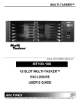
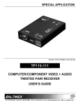
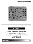
TABLETOP SOLUTIONS
TNP121 Front View
TNP151 Front View
MANUAL PART NUMBER: 400-0434-005
TNP121 / 121C
TNP122 / 131 / 142
TNP151 / 151C
TILT ‘N PLUG® JR.
INTERCONNECT BOXES
USER'S GUIDE
TABLETOP SOLUTIONS
TABLE OF CONTENTS
INTRODUCTION
Page
PRECAUTIONS / SAFETY WARNINGS............... 2
GENERAL ......................................................... 2
INSTALLATION PRECAUTIONS....................... 2
CLEANING ........................................................ 2
FCC NOTICE..................................................... 2
ABOUT YOUR TILT 'N PLUG JR........................... 3
TECHNICAL SPECIFICATIONS ............................ 3
TILT 'N PLUG JR. DIMENSIONS ........................... 5
DIAGRAM 1: ROUND BEZEL DIMENSIONS..... 5
DIAGRAM 2: SINGLE UNIT DIMENSIONS........ 6
DIAGRAM 3: DUAL UNIT DIMENSIONS ........... 6
DESCRIPTION DIAGRAM ...................................... 7
DIAGRAM 4: STANDARD FACEPLATES ......... 7
MOUNTING DIAGRAM............................................ 8
DIAGRAM 5: MOUNTING A TNP JR. ................ 8
INSTALLATION PROCEDURES............................ 9
TROUBLESHOOTING GUIDE ............................... 9
ALTINEX POLICIES .............................................. 10
LIMITED WARRANTY/RETURN POLICIES .... 10
CONTACT INFORMATION.............................. 10
We greatly appreciate your purchase of the
Tilt ‘N Plug Jr. (TNP JR.) Interconnect Box. We
are sure you will find it reliable and simple to use.
Superior performance for the right price, backed by
solid technical and customer support is what
ALTINEX has to offer.
The product you are holding is designed using
state-of-the-art technology and is superior to
anything available on the market. You will find this
and our other products reliable, long-lasting, and
simple to operate.
We are committed to providing our customers with
®
Signal Management Solutions
to
the
most
demanding audiovisual installations at very
competitive pricing.
We appreciate your selection of our products and
are confident that you will join the ranks of our
many satisfied customers throughout the world.
400-0434-005
1
TABLETOP SOLUTIONS
PRECAUTIONS / SAFETY WARNINGS
1.3 CLEANING
1
•
Surfaces should be cleaned with a dry cloth.
Never use strong detergents or solvents such
as alcohol or thinner. Do not use a wet cloth or
water to clean the unit.
1.4 FCC NOTICE
Please read this manual carefully before using
your Tilt ‘N Plug Jr. Interconnect Box. Keep this
manual handy for future reference. These safety
instructions are to ensure the long life of your
Tilt ‘N Plug Jr. and to prevent fire and shock
hazards. Please read them carefully and heed all
warnings.
•
This device complies with Part 15 of the FCC
Rules. Operation is subject to the following two
conditions: (1) This device may not cause
harmful interference, and (2) this device must
accept any interference received, including
interference that may cause undesired
operation.
•
This equipment has been tested and found to
comply with the limits for a Class A digital
device, pursuant to Part 15 of the FCC Rules.
These limits are designed to provide reasonable
protection against harmful interference when
the equipment is operated in a commercial
environment. This equipment generates, uses,
and can radiate radio frequency energy and, if
not installed and used in accordance with the
instructions found herein, may cause harmful
interference to radio communications. Operation
of this equipment in a residential area is likely to
cause harmful interference in which case the
user will be required to correct the interference
at his expense.
•
Any changes or modifications to the unit not
expressly approved by ALTINEX, Inc. could void
the user’s authority to operate the equipment.
1.1 GENERAL
•
Unauthorized personnel shall not open the unit
as there are high-voltage components inside.
•
Qualified ALTINEX service personnel or their
authorized representatives must perform all
service.
1.2 INSTALLATION PRECAUTIONS
•
For best results, place the Tilt ‘N Plug Jr. in a
dry area away from dust.
•
To prevent fire or shock, do not expose this unit
to water or moisture. Do not place the unit in
direct sunlight, near heaters or heat-radiating
appliances, or near any liquid. Exposure to
direct sunlight, smoke, or steam can harm
internal components.
•
Handle the Tilt ‘N Plug Jr. carefully. Dropping
or jarring can damage the bezel.
•
Never place fingers inside the opening on either
side of the unit. This action could cause injury
due to sharp edges inside.
•
Do not place heavy objects on top of the
Tilt ‘N Plug Jr. Do not use excessive force to
push down on the top of the unit.
•
Disconnect the power cord to turn off the power.
This supplies power to the socket on the pop-up
panel. The power outlet should be installed near
the equipment and be easily accessible.
•
We recommend using wall outlets with a
Ground Fault Circuit Interrupter (GFCI) for
maximum protection.
•
Install all cables according to the instructions
found herein. Do not force or pull any cable that
is attached to the Tilt ‘N Plug Jr.
400-0434-005
2
TABLETOP SOLUTIONS
ABOUT YOUR Tilt 'N Plug Jr.
2
TECHNICAL SPECIFICATIONS
Specifications are subject to change.
See www.altinex.com for up-to-date information.
TILT ‘N PLUG JR.
Designer Interconnect Solutions
FEATURES/
DESCRIPTION
All Tilt ‘N Plug Jr.’s belong to a family of compact
interconnection solutions designed for installation
into a table as part of a presentation system. They
are designed for mounting into a table, podium, or
other furniture to provide a way of connecting
audiovisual equipment on top of the furniture to a
presentation system below the furniture.
TNP121/121C/131
PASS-THROUGH
All use the same core element; a multimedia input
plate that can be "tilted" open when needed and
pushed closed when not needed.
AC Power
10 ft (3 m)
110 VAC, 60 Hz, 5 A
Audio, Video, and
Communication *
Computer Video
NEMA F-M
6 ft (2 m)
15-pin HD F-M (1)
Stereo Audio
The TNP122 and TNP142 each incorporate two
Tilt ‘N Plug Jr. modules and are operated
independently. The TNP142 is the same as a
TNP122, but with the modules factory-installed
facing in opposite directions. The TNP131 is the
same as a TNP121, but with a round bezel instead
of a square bezel.
3.5 mm F-M (1)
Network
RJ-45 F-M (1)
Modem
RJ-11 F-M (1)
Accessories Included
Hardware
- Mounting screws and
brackets
- Cable clamps/screws
Table 1. TNP121/121C/131 General
All signals pass through the input plate directly to
cables on the underside of the table with no
intervening circuitry. The use of additional
ALTINEX Signal Management Solutions® such as
computer video interfaces, distribution amplifiers,
and switchers may be desirable.
FEATURES/
DESCRIPTION
TNP122/142
PASS-THROUGH
AC Power
110 VAC, 60 Hz, 5 A
The input plate of the Tilt ‘N Plug Jr. is accessible
by pushing down on the top cover. The unit then
auto-tilts open with help from an internal
pneumatic spring. Once open, the input plate
remains securely in place. The input plate is
hidden by pressing down on the top cover until the
latching mechanism engages. In its closed
position, the top panel lies flush with the tabletop,
held in place by the latching mechanism.
Audio, Video, and
Communication
Computer Video
10 ft (3 m)
NEMA F-M
(2 female to 1 male)
6 ft (2 m)
15-pin HD F-M (2)
Computer Audio
3.5mm F-M (2)
Network
CAT-6 (RJ-45) F-M (2)
Modem
RJ-11 F-M (2)
Accessories Included
All Tilt ‘N Plug Jr. Signal Management Solutions
come with a standard top and bezel offering a high
quality matte black finish. Other finishes or special
bezel configurations are available upon request.
Please contact an ALTINEX representative to
discuss custom options.
Hardware
- Mounting screws and
brackets
- Cable clamps/screws
Table 2. TNP122/142 General
* Customizable on the TNP121C
400-0434-005
3
3
TABLETOP SOLUTIONS
FEATURES/
DESCRIPTION
MECHANICAL
TNP151/151C
PASS-THROUGH
AC Power
10 ft (3 m)
NEMA F-M
(2 female to 1 male)
110 VAC, 60 Hz, 5 A
Audio, Video, and
Communication *
6 ft (2 m)
Network
CAT-6 (RJ-45) F-M (2)
Accessories Included
Hardware
- Mounting screws and
brackets
- Cable clamps/screws
Table 3. TNP151/151C General
TNP122/142
Max. Table Thickness
2.3 in (58 mm)
Height, opened
5.5 in (140 mm)
Width
8.7 in (221 mm)
Depth
4.9 in (124 mm)
Finish
Matte Black
Weight (approx.)
3.7 lb (1.7 kg)
Shipping Weight
5.4 lb (2.5 kg)
T° Operating
10°C-35°C
T° Maximum
40°C
Humidity
MECHANICAL
TNP121/121C/
131/151/151C
90% non-condensing
Max. Table Thickness
2.3 in (58 mm)
Height, opened
5.5 in (140 mm)
ELECTRICAL
(Single outlet panel)
TNP121/121C/
122/131/142
Width ........(TNP121/151)
Diameter ...(TNP131)
4.6 in (117 mm)
5.8 in (147 mm)
Power Rating
110VAC, 60Hz,
Depth ........(TNP121/151)
4.9 in (124 mm)
Table 5. TNP122/142 Mechanical
(pass-through AC power)
5A per connector
Weight (approx.)
2.8 lb (1.3 kg)
Table 6. TNP121/121C/122/131/142 Electrical
Shipping Weight
4.5 lb (2.0 kg)
ELECTRICAL
(Dual outlet panel)
Finish
T° Operating (T° Max)
Humidity
Matte Black
Power Rating
10°C-35°C (40°C)
(pass-through AC power)
90% non-condensing
110VAC, 60Hz,
2.5A per connector
Table 7. TNP151/151C Electrical
Table 4. TNP121/121C/131/151/151C Mechanical
* Customizable on the TNP151C
400-0434-005
TNP151 and
TNP151C
4
TABLETOP SOLUTIONS
Tilt 'N Plug Jr. DIMENSIONS
NOTE:
4
Detailed dimensions, tabletop cutout templates, and drawings are available on the
ALTINEX website at www.altinex.com
DIAGRAM 1: ROUND BEZEL DIMENSIONS
5.75"
[146mm]
TNP131
Dimensions
1.97"
[50mm]
5.50"
[140mm]
3.53"
[90mm]
400-0434-005
5
TABLETOP SOLUTIONS
DIAGRAM 2: SINGLE UNIT DIMENSIONS
4.60"
[117mm]
TNP121, TNP121C,
TNP151, TNP151C
Dimensions
4.90"
[124.5mm]
1.97''
[50mm]
5.50''
[140mm]
3.53''
[90mm]
DIAGRAM 3: DUAL UNIT DIMENSIONS
8.70''
[221mm]
TNP122, TNP142
Dimensions
4.90''
[124.5mm]
1.97''
[50mm]
5.50''
[140mm]
3.53''
[90mm]
400-0434-005
6
TABLETOP SOLUTIONS
DESCRIPTION DIAGRAM
5
DIAGRAM 4: STANDARD FACEPLATES
TNP121
15-pin HD VGA
3.5mm Audio Jack
Power
110VAC, 5A
RJ-11 Phone Jack
CAT-6 (RJ-45) Network Jack
TNP151
Power
110VAC, 2.5A
Power
110VAC, 2.5A
CAT-6 (RJ-45) Network Jack ( 2 )
400-0434-005
7
TABLETOP SOLUTIONS
MOUNTING DIAGRAM
6
DIAGRAM 5: MOUNTING A TNP JR.
Tabletop
Support
Bracket
Support
Bracket
Table
Securing
Screw
400-0434-005
Table
Securing
Screw
8
TABLETOP SOLUTIONS
INSTALLATION PROCEDURES
7
TROUBLESHOOTING GUIDE
Step 1. Cut an opening into the table’s surface.
Refer to the ALTINEX website at
www.altinex.com
for
table
cutout
requirements.
The Tilt ‘N Plug Jr. supplied was carefully tested
and no problems were detected. However, we
would like to offer the following suggestions:
Note: The table can be 2.25” or less in
thickness. Always confirm dimensions
before cutting to insure that specifications
have not changed.
•
Please make sure that the highest quality
network cables are used.
•
Make sure that no cable or power cord is
damaged or pinched. If there has been
damage, do not use the Tilt ‘N Plug Jr. Please
call the ALTINEX Customer Service Department
at (714) 990-2300 to have the unit repaired.
•
If the unit does not rise into position correctly,
check the service loops for the signal and power
cords on the bottom of the unit.
Step 2. Insert the Tilt ‘N Plug Jr. into the table
cutout.
Step 3. Place the support brackets under the
table in between the support mount
grooves on the side of the Tilt ‘N Plug Jr.
(See Diagram 5 for details.) Attach the
brackets to the groove at the desired
height and secure them to the bottom of
the table using the thumb screws
provided.
Step 4. Secure the cables by using the provided
cable clamps and screws included with
the unit. Pass the power cord from the
bottom of the housing and attach it to the
table using the cable clamp and screw
supplied with the Tilt ‘N Plug Jr.
Leave enough slack in the service loop to
allow for easy opening and closing, but
not too much as to cause excess
drooping of the service loop.
Step 5. Connect the appropriate cables with the
correct input connectors on the bottom of
the unit.
Step 6. Once you have applied power and
connected the proper cables on the
bottom of the unit you may raise the unit.
To raise the Tilt ‘N Plug Jr. into position,
push down on the front of the top cover;
the latching mechanism will then release,
allowing the pneumatic spring to raise it
into position.
Step 7. To lower the unit, push on the top of the
Tilt ‘N Plug Jr. until it locks into place.
400-0434-005
8
9
TABLETOP SOLUTIONS
ALTINEX POLICIES
9
9.1 LIMITED WARRANTY/RETURN POLICIES
Please see the ALTINEX website at
www.altinex.com for details on warranty and
return policies.
9.2 CONTACT INFORMATION
ALTINEX, Inc.
592 Apollo Street
Brea, CA 92821 USA
TEL: 714 990-2300
TOLL FREE: 1-800-ALTINEX
WEB: www.altinex.com
E-MAIL: [email protected]
400-0434-005
10