1
Management
Software
AT-S63
◆
Features Guide
For Stand-alone AT-9400 Switches
and AT-9400Ts Stacks
AT-S63 Version 2.2.0 for AT-9400 Layer 2+ Switches
AT-S63 Version 4.1.0 for AT-9400 Basic Layer 3 Switches
613-001022 Rev. C
Copyright 2009 Allied Telesis, Inc.
All rights reserved. No part of this publication may be reproduced without prior written permission from Allied Telesis, Inc.
Allied Telesis and the Allied Telesis logo are trademarks of Allied Telesis, Incorporated. Microsoft and Internet Explorer are registered
trademarks of Microsoft Corporation. All other product names, company names, logos or other designations mentioned herein are
trademarks or registered trademarks of their respective owners.
Allied Telesis, Inc. reserves the right to make changes in specifications and other information contained in this document without prior
written notice. The information provided herein is subject to change without notice. In no event shall Allied Telesis, Inc. be liable for any
incidental, special, indirect, or consequential damages whatsoever, including but not limited to lost profits, arising out of or related to this
manual or the information contained herein, even if Allied Telesis, Inc. has been advised of, known, or should have known, the possibility of
such damages.
Contents
Preface ............................................................................................................................................................ 21
How This Guide is Organized........................................................................................................................... 22
Product Documentation .................................................................................................................................... 25
Where to Go First ............................................................................................................................................. 26
Starting a Management Session ...................................................................................................................... 27
Document Conventions .................................................................................................................................... 28
Contacting Allied Telesis .................................................................................................................................. 29
Online Support ........................................................................................................................................... 29
Email and Telephone Support.................................................................................................................... 29
Returning Products .................................................................................................................................... 29
Sales or Corporate Information .................................................................................................................. 29
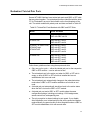
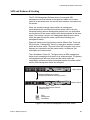
Management Software Updates................................................................................................................. 29
Section I: Basic Operations ...................................................................................... 31
Chapter 1: Overview ...................................................................................................................................... 33
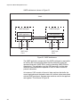
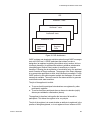
Layer 2+ and Basic Layer 3 Switches .............................................................................................................. 34
AT-S63 Management Software ........................................................................................................................ 40
Management Interfaces.................................................................................................................................... 41
Management Access Methods ......................................................................................................................... 47
Local Management Sessions ..................................................................................................................... 47
Remote Telnet Sessions ............................................................................................................................ 47
Remote Secure Shell (SSH) Sessions....................................................................................................... 48
Remote Web Browser Session .................................................................................................................. 48
Remote SNMP Management ..................................................................................................................... 48
Manager Access Levels ................................................................................................................................... 49
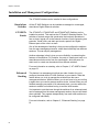
Installation and Management Configurations ................................................................................................... 50
Stand-alone Switches ................................................................................................................................ 50
AT-9400Ts Stacks...................................................................................................................................... 50
Enhanced Stacking .................................................................................................................................... 50
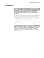
IP Configuration................................................................................................................................................ 51
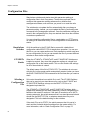
Configuration Files............................................................................................................................................ 52
Stand-alone Switches ................................................................................................................................ 52
AT-9400Ts Stacks...................................................................................................................................... 52
Selecting a Configuration File .................................................................................................................... 52
Redundant Twisted Pair Ports.......................................................................................................................... 53
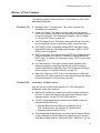
History of New Features ................................................................................................................................... 55
Version 4.1.0 .............................................................................................................................................. 55
Version 4.0.0 .............................................................................................................................................. 55
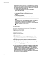
Version 3.2.0 .............................................................................................................................................. 57
Version 3.0.0 .............................................................................................................................................. 58
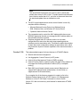
Version 2.1.0 .............................................................................................................................................. 59
Version 2.0.0 .............................................................................................................................................. 59
Version 1.3.0 .............................................................................................................................................. 60
Version 1.2.0 .............................................................................................................................................. 61
3
Contents
Chapter 2: AT-9400Ts Stacks ....................................................................................................................... 63
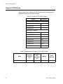
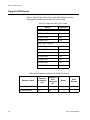
Supported Platforms ......................................................................................................................................... 64
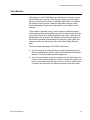
Introduction .......................................................................................................................................................65
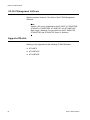
AT-S63 Management Software......................................................................................................................... 66
Supported Models ............................................................................................................................................. 66
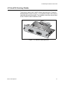
AT-StackXG Stacking Module .......................................................................................................................... 67
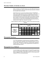
Maximum Number of Switches in a Stack......................................................................................................... 68
Management Interfaces .................................................................................................................................... 68
Management Access Methods.......................................................................................................................... 68
Enhanced Stacking ........................................................................................................................................... 69
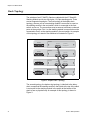
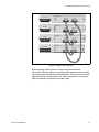
Stack Topology ................................................................................................................................................. 70
Discovery Process ............................................................................................................................................ 72
Master and Member Switches .......................................................................................................................... 73
Module ID Numbers .......................................................................................................................................... 74
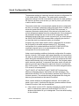
Stack Configuration Files .................................................................................................................................. 75
MAC Address Tables ........................................................................................................................................ 77
File Systems ..................................................................................................................................................... 77
Compact Flash Memory Card Slots .................................................................................................................. 77
Stack IP Address .............................................................................................................................................. 78
Upgrading the AT-S63 Management Software ................................................................................................. 79
Chapter 3: Enhanced Stacking ..................................................................................................................... 81
Supported Platforms ......................................................................................................................................... 82
Overview ........................................................................................................................................................... 83
Master and Slave Switches............................................................................................................................... 84
Common VLAN ................................................................................................................................................. 85
Master Switch and the Local Interface .............................................................................................................. 86
Slave Switches.................................................................................................................................................. 87
Enhanced Stacking Compatibility ..................................................................................................................... 88
Enhanced Stacking Guidelines ......................................................................................................................... 89
General Steps ................................................................................................................................................... 90
Chapter 4: SNMPv1 and SNMPv2c ............................................................................................................... 91
Supported Platforms ......................................................................................................................................... 92
Overview ........................................................................................................................................................... 93
Community String Attributes ............................................................................................................................. 94
Community String Name ............................................................................................................................ 94
Access Mode .............................................................................................................................................. 94
Operating Status......................................................................................................................................... 94
Open or Closed Access Status................................................................................................................... 94
Trap Receivers ........................................................................................................................................... 94
Default SNMP Community Strings .................................................................................................................... 96
Chapter 5: MAC Address Table .................................................................................................................... 97
Overview ........................................................................................................................................................... 98
Chapter 6: Static Port Trunks .....................................................................................................................101
Supported Platforms .......................................................................................................................................102
Overview .........................................................................................................................................................103
Load Distribution Methods ..............................................................................................................................104
Guidelines .......................................................................................................................................................106
Chapter 7: LACP Port Trunks .....................................................................................................................107
Supported Platforms .......................................................................................................................................108
Overview .........................................................................................................................................................109
LACP System Priority .....................................................................................................................................110
Adminkey Parameter ......................................................................................................................................111
LACP Port Priority Value.................................................................................................................................111
4
AT-S63 Management Software Features Guide
Load Distribution Methods.............................................................................................................................. 112
Guidelines....................................................................................................................................................... 113
Chapter 8: Port Mirror ................................................................................................................................. 115
Supported Platforms....................................................................................................................................... 116
Overview......................................................................................................................................................... 117
Guidelines....................................................................................................................................................... 117
Chapter 9: Link-flap Protection .................................................................................................................. 119
Supported Platforms....................................................................................................................................... 120
Overview......................................................................................................................................................... 121
Guidelines....................................................................................................................................................... 122
Configuring the Feature.................................................................................................................................. 123
Section II: Advanced Operations ........................................................................... 125
Chapter 10: File System .............................................................................................................................. 127
Overview......................................................................................................................................................... 128
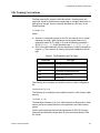
File Naming Conventions ............................................................................................................................... 129
Using Wildcards to Specify Groups of Files ................................................................................................... 130
Chapter 11: Event Logs and the Syslog Client ......................................................................................... 131
Supported Platforms....................................................................................................................................... 132
Overview......................................................................................................................................................... 133
Event Messages ............................................................................................................................................. 133
Syslog Client................................................................................................................................................... 134
Chapter 12: Classifiers ................................................................................................................................ 135
Supported Platforms....................................................................................................................................... 136
Overview......................................................................................................................................................... 137
Classifier Criteria ............................................................................................................................................ 139
Guidelines....................................................................................................................................................... 144
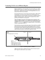
Chapter 13: Access Control Lists .............................................................................................................. 145
Supported Platforms....................................................................................................................................... 146
Overview......................................................................................................................................................... 147
Parts of an ACL .............................................................................................................................................. 149
Guidelines....................................................................................................................................................... 150
Examples........................................................................................................................................................ 151
Chapter 14: Class of Service ...................................................................................................................... 157
Supported Platforms....................................................................................................................................... 158
Overview......................................................................................................................................................... 159
Scheduling...................................................................................................................................................... 162
Strict Priority Scheduling .......................................................................................................................... 162
Weighted Round Robin Priority Scheduling ............................................................................................. 162
Chapter 15: Quality of Service ................................................................................................................... 165
Supported Platforms....................................................................................................................................... 166
Overview......................................................................................................................................................... 167
Classifiers ....................................................................................................................................................... 169
Flow Groups ................................................................................................................................................... 170
Traffic Classes................................................................................................................................................ 171
Policies ........................................................................................................................................................... 172
QoS Policy Guidelines.................................................................................................................................... 173
Packet Processing.......................................................................................................................................... 174
Bandwidth Allocation ...................................................................................................................................... 174
Packet Prioritization........................................................................................................................................ 174
5
Contents
Replacing Priorities .........................................................................................................................................176
VLAN Tag User Priorities ................................................................................................................................176
DSCP Values ..................................................................................................................................................176
DiffServ Domains ............................................................................................................................................177
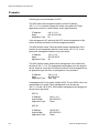
Examples ........................................................................................................................................................179
Voice Applications ....................................................................................................................................179
Video Applications ....................................................................................................................................181
Critical Database ......................................................................................................................................183
Policy Component Hierarchy ....................................................................................................................184
Chapter 16: Group Link Control .................................................................................................................187
Supported Platforms .......................................................................................................................................188
Overview .........................................................................................................................................................189
Guidelines .......................................................................................................................................................197
Configuring the Feature ..................................................................................................................................198
Chapter 17: Denial of Service Defenses ....................................................................................................201
Supported Platforms .......................................................................................................................................202
Overview .........................................................................................................................................................203
SYN Flood Attack............................................................................................................................................204
Smurf Attack ...................................................................................................................................................205
Land Attack .....................................................................................................................................................206
Teardrop Attack ..............................................................................................................................................208
Ping of Death Attack .......................................................................................................................................209
IP Options Attack ............................................................................................................................................210
Mirroring Traffic ...............................................................................................................................................211
Denial of Service Defense Guidelines ............................................................................................................212
Chapter 18: Power Over Ethernet ...............................................................................................................213
Supported Platforms .......................................................................................................................................214
Overview .........................................................................................................................................................215
Power Budgeting.............................................................................................................................................216
Port Prioritization.............................................................................................................................................217
PoE Device Classes .......................................................................................................................................218
Section III: Snooping Protocols ..............................................................................219
Chapter 19: Internet Group Management Protocol Snooping .................................................................221
Supported Platforms .......................................................................................................................................222
Overview .........................................................................................................................................................223
Chapter 20: Internet Group Management Protocol Snooping Querier ...................................................225
Supported Platforms .......................................................................................................................................226
Overview .........................................................................................................................................................227
Guidelines .......................................................................................................................................................230
Configuring the Feature ..................................................................................................................................231
Chapter 21: Multicast Listener Discovery Snooping ................................................................................235
Supported Platforms .......................................................................................................................................236
Overview .........................................................................................................................................................237
Chapter 22: Router Redundancy Protocol Snooping ...............................................................................239
Supported Platforms .......................................................................................................................................240
Overview .........................................................................................................................................................241
Guidelines .......................................................................................................................................................242
6
AT-S63 Management Software Features Guide
Chapter 23: Ethernet Protection Switching Ring Snooping .................................................................... 243
Supported Platforms....................................................................................................................................... 244
Overview......................................................................................................................................................... 245
Restrictions..................................................................................................................................................... 247
Guidelines....................................................................................................................................................... 249
Section IV: SNMPv3 ............................................................................................... 251
Chapter 24: SNMPv3 ................................................................................................................................... 253
Supported Platforms....................................................................................................................................... 254
Overview......................................................................................................................................................... 255
SNMPv3 Authentication Protocols.................................................................................................................. 256
SNMPv3 Privacy Protocol .............................................................................................................................. 257
SNMPv3 MIB Views ....................................................................................................................................... 258
SNMPv3 Storage Types ................................................................................................................................. 260
SNMPv3 Message Notification ....................................................................................................................... 261
SNMPv3 Tables.............................................................................................................................................. 262
SNMPv3 User Table ................................................................................................................................ 264
SNMPv3 View Table ................................................................................................................................ 264
SNMPv3 Access Table ............................................................................................................................ 264
SNMPv3 SecurityToGroup Table............................................................................................................. 264
SNMPv3 Notify Table............................................................................................................................... 265
SNMPv3 Target Address Table ............................................................................................................... 265
SNMPv3 Target Parameters Table .......................................................................................................... 265
SNMPv3 Community Table...................................................................................................................... 265
SNMPv3 Configuration Example .................................................................................................................... 266
Section V: Spanning Tree Protocols ...................................................................... 267
Chapter 25: Spanning Tree and Rapid Spanning Tree Protocols ........................................................... 269
Supported Platforms....................................................................................................................................... 270
Overview......................................................................................................................................................... 271
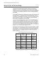
Bridge Priority and the Root Bridge ................................................................................................................ 272
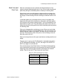
Path Costs and Port Costs....................................................................................................................... 273
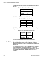
Port Priority .............................................................................................................................................. 274
Forwarding Delay and Topology Changes ..................................................................................................... 276
Hello Time and Bridge Protocol Data Units (BPDU) ................................................................................ 276
Point-to-Point and Edge Ports.................................................................................................................. 277
Mixed STP and RSTP Networks .................................................................................................................... 279
Spanning Tree and VLANs............................................................................................................................. 280
RSTP BPDU Guard ........................................................................................................................................ 281
RSTP Loop Guard .......................................................................................................................................... 283
Chapter 26: Multiple Spanning Tree Protocol ........................................................................................... 289
Supported Platforms....................................................................................................................................... 290
Overview......................................................................................................................................................... 291
Multiple Spanning Tree Instance (MSTI) ........................................................................................................ 292
MSTI Guidelines ............................................................................................................................................. 296
VLAN and MSTI Associations ........................................................................................................................ 297
Ports in Multiple MSTIs................................................................................................................................... 298
Multiple Spanning Tree Regions .................................................................................................................... 299
Region Guidelines.................................................................................................................................... 301
Common and Internal Spanning Tree (CIST) .......................................................................................... 302
MSTP with STP and RSTP ...................................................................................................................... 302
Summary of Guidelines .................................................................................................................................. 303
7
Contents
Associating VLANs to MSTIs ..........................................................................................................................305
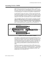
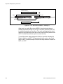
Connecting VLANs Across Different Regions .................................................................................................307
Section VI: Virtual LANs .......................................................................................309
Chapter 27: Port-based and Tagged VLANs ..............................................................................................311
Supported Platforms .......................................................................................................................................312
Overview .........................................................................................................................................................313
Port-based VLAN Overview ............................................................................................................................315
VLAN Name..............................................................................................................................................315
VLAN Identifier .........................................................................................................................................315
Untagged Ports.........................................................................................................................................316
Port VLAN Identifier..................................................................................................................................316
Guidelines to Creating a Port-based VLAN ..............................................................................................317
Drawbacks of Port-based VLANs .............................................................................................................317
Port-based Example 1 ..............................................................................................................................318
Port-based Example 2 ..............................................................................................................................319
Tagged VLAN Overview .................................................................................................................................321
Tagged and Untagged Ports ....................................................................................................................322
Port VLAN Identifier..................................................................................................................................322
Guidelines to Creating a Tagged VLAN ...................................................................................................322
Tagged VLAN Example ............................................................................................................................323
Chapter 28: GARP VLAN Registration Protocol ........................................................................................325
Supported Platforms .......................................................................................................................................326
Overview .........................................................................................................................................................327
Guidelines .......................................................................................................................................................330
GVRP and Network Security...........................................................................................................................331
GVRP-inactive Intermediate Switches ............................................................................................................332
Generic Attribute Registration Protocol (GARP) Overview .............................................................................333
Chapter 29: Multiple VLAN Modes ..............................................................................................................337
Supported Platforms .......................................................................................................................................338
Overview .........................................................................................................................................................339
802.1Q- Compliant Multiple VLAN Mode ........................................................................................................340
Non-802.1Q Compliant Multiple VLAN Mode .................................................................................................342
Chapter 30: Protected Ports VLANs ...........................................................................................................343
Supported Platforms .......................................................................................................................................344
Overview .........................................................................................................................................................345
Guidelines .......................................................................................................................................................347
Chapter 31: MAC Address-based VLANs ..................................................................................................349
Supported Platforms .......................................................................................................................................350
Overview .........................................................................................................................................................351
Egress Ports ...................................................................................................................................................352
VLANs That Span Switches ............................................................................................................................355
VLAN Hierarchy ..............................................................................................................................................357
Steps to Creating a MAC Address-based VLAN.............................................................................................358
Guidelines .......................................................................................................................................................359
8
AT-S63 Management Software Features Guide
Section VII: Internet Protocol Routing ................................................................. 361
Chapter 32: Internet Protocol Version 4 Packet Routing ......................................................................... 363
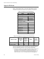
Supported Platforms....................................................................................................................................... 364
Overview......................................................................................................................................................... 366
Routing Interfaces .......................................................................................................................................... 368
VLAN ID (VID).......................................................................................................................................... 369
Interface Numbers.................................................................................................................................... 369
IP Address and Subnet Mask................................................................................................................... 369
Interface Names ............................................................................................................................................. 371
Static Routes .................................................................................................................................................. 372
Routing Information Protocol (RIP)................................................................................................................. 374
Default Routes................................................................................................................................................ 376
Equal-cost Multi-path (ECMP) Routing........................................................................................................... 377
Routing Table ................................................................................................................................................. 379
Route Selection Process ................................................................................................................................ 380
Address Resolution Protocol (ARP) Table ..................................................................................................... 381
Internet Control Message Protocol (ICMP)..................................................................................................... 382
Routing Interfaces and Management Features .............................................................................................. 384
Accessing Network Servers ..................................................................................................................... 384
Enhanced Stacking .................................................................................................................................. 385
Remote Telnet, SSH, and Web Browser Management Sessions ............................................................ 385
Pinging a Remote Device......................................................................................................................... 386
Accessing DHCP or BOOTP Servers ...................................................................................................... 386
Local Interface ................................................................................................................................................ 387
AT-9408LC/SP AT-9424T/GB, and AT-9424T/SP Switches .......................................................................... 388
Local Interface.......................................................................................................................................... 388
ARP Table................................................................................................................................................ 388
Default Gateway....................................................................................................................................... 389
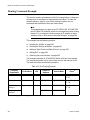
Routing Command Example........................................................................................................................... 390
Creating the VLANs ................................................................................................................................. 391
Creating the Routing Interfaces ............................................................................................................... 391
Adding a Static Route and Default Route ................................................................................................ 392
Adding RIP ............................................................................................................................................... 393
Selecting the Local Interface.................................................................................................................... 393
Non-routing Command Example .................................................................................................................... 394
Upgrading from AT-S63 Version 1.3.0 or Earlier............................................................................................ 396
Chapter 33: BOOTP Relay Agent ............................................................................................................... 397
Supported Platforms....................................................................................................................................... 398
Overview......................................................................................................................................................... 399
Guidelines....................................................................................................................................................... 401
Chapter 34: Virtual Router Redundancy Protocol .................................................................................... 403
Supported Platforms....................................................................................................................................... 404
Overview......................................................................................................................................................... 405
Master Switch ................................................................................................................................................. 406
Backup Switches ............................................................................................................................................ 407
Interface Monitoring........................................................................................................................................ 408
Port Monitoring ............................................................................................................................................... 409
VRRP on the Switch ....................................................................................................................................... 410
9
Contents
Section VIII: Port Security .....................................................................................413
Chapter 35: MAC Address-based Port Security ........................................................................................415
Supported Platforms .......................................................................................................................................416
Overview .........................................................................................................................................................417
Automatic..................................................................................................................................................417
Limited ......................................................................................................................................................417
Secured ....................................................................................................................................................418
Locked ......................................................................................................................................................418
Invalid Frames and Intrusion Actions ..............................................................................................................419
Guidelines .......................................................................................................................................................420
Chapter 36: 802.1x Port-based Network Access Control .........................................................................421
Supported Platforms .......................................................................................................................................422
Overview .........................................................................................................................................................423
Authentication Process ...................................................................................................................................425
Port Roles .......................................................................................................................................................426
None Role.................................................................................................................................................426
Authenticator Role ....................................................................................................................................426
Supplicant Role ........................................................................................................................................428
Authenticator Ports with Single and Multiple Supplicants ...............................................................................429
Single Operating Mode.............................................................................................................................429
Multiple Operating Mode ..........................................................................................................................433
Supplicant and VLAN Associations.................................................................................................................436
Single Operating Mode.............................................................................................................................437
Multiple Operating Mode ..........................................................................................................................437
Supplicant VLAN Attributes on the RADIUS Server .................................................................................437
Guest VLAN ....................................................................................................................................................438
RADIUS Accounting........................................................................................................................................439
General Steps .................................................................................................................................................440
Guidelines .......................................................................................................................................................441
Section IX: Management Security .........................................................................445
Chapter 37: Web Server ..............................................................................................................................447
Supported Platforms .......................................................................................................................................448
Overview .........................................................................................................................................................449
Supported Protocols .................................................................................................................................449
Configuring the Web Server for HTTP ............................................................................................................450
Configuring the Web Server for HTTPS..........................................................................................................451
General Steps for a Self-signed Certificate ..............................................................................................451
General Steps for a Public or Private CA Certificate ................................................................................451
Chapter 38: Encryption Keys ......................................................................................................................453
Supported Platforms .......................................................................................................................................454
Overview .........................................................................................................................................................455
Encryption Key Length ....................................................................................................................................456
Encryption Key Guidelines ..............................................................................................................................457
Technical Overview.........................................................................................................................................458
Data Encryption ........................................................................................................................................458
Data Authentication ..................................................................................................................................460
Key Exchange Algorithms ........................................................................................................................461
10
AT-S63 Management Software Features Guide
Chapter 39: PKI Certificates and SSL ........................................................................................................ 463
Supported Platforms....................................................................................................................................... 464
Overview......................................................................................................................................................... 465
Types of Certificates....................................................................................................................................... 465
Distinguished Names...................................................................................................................................... 467
SSL and Enhanced Stacking.......................................................................................................................... 469
Guidelines....................................................................................................................................................... 470
Technical Overview ........................................................................................................................................ 471
SSL Encryption ........................................................................................................................................ 471
User Verification....................................................................................................................................... 472
Authentication .......................................................................................................................................... 472
Public Key Infrastructure .......................................................................................................................... 473
Public Keys .............................................................................................................................................. 473
Message Encryption................................................................................................................................. 473
Digital Signatures ..................................................................................................................................... 473
Certificates ............................................................................................................................................... 474
Elements of a Public Key Infrastructure ................................................................................................... 475
Certificate Validation ................................................................................................................................ 476
Certificate Revocation Lists (CRLs) ......................................................................................................... 476
PKI Implementation.................................................................................................................................. 477
Chapter 40: Secure Shell (SSH) ................................................................................................................. 479
Supported Platforms....................................................................................................................................... 480
Overview......................................................................................................................................................... 481
Support for SSH ............................................................................................................................................. 482
SSH Server..................................................................................................................................................... 483
SSH Clients .................................................................................................................................................... 484
SSH and Enhanced Stacking ......................................................................................................................... 485
SSH Configuration Guidelines........................................................................................................................ 487
General Steps to Configuring SSH................................................................................................................. 488
Chapter 41: TACACS+ and RADIUS Protocols ......................................................................................... 489
Supported Platforms....................................................................................................................................... 490
Overview......................................................................................................................................................... 491
Guidelines....................................................................................................................................................... 493
Chapter 42: Management Access Control List ......................................................................................... 497
Supported Platforms....................................................................................................................................... 498
Overview......................................................................................................................................................... 499
Parts of a Management ACE.......................................................................................................................... 500
IP Address................................................................................................................................................ 500
Mask......................................................................................................................................................... 500
Application................................................................................................................................................ 500
Guidelines....................................................................................................................................................... 501
Examples........................................................................................................................................................ 502
Appendix A: AT-S63 Management Software Default Settings ................................................................ 505
Address Resolution Protocol Cache............................................................................................................... 507
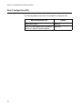
Boot Configuration File ................................................................................................................................... 508
BOOTP Relay Agent ...................................................................................................................................... 509
Class of Service.............................................................................................................................................. 510
Denial of Service Defenses ............................................................................................................................ 511
802.1x Port-Based Network Access Control .................................................................................................. 512
Enhanced Stacking......................................................................................................................................... 514
Ethernet Protection Switching Ring (EPSR) Snooping................................................................................... 515
Event Logs...................................................................................................................................................... 516
GVRP ............................................................................................................................................................. 517
IGMP Snooping .............................................................................................................................................. 518
11
Contents
Internet Protocol Version 4 Packet Routing ....................................................................................................519
Link-flap Protection .........................................................................................................................................520
MAC Address-based Port Security .................................................................................................................521
MAC Address Table ........................................................................................................................................522
Management Access Control List ...................................................................................................................523
Manager and Operator Account......................................................................................................................524
Multicast Listener Discovery Snooping ...........................................................................................................525
Public Key Infrastructure .................................................................................................................................526
Port Settings ...................................................................................................................................................527
RJ-45 Serial Terminal Port..............................................................................................................................528
Router Redundancy Protocol Snooping..........................................................................................................529
Server-based Authentication (RADIUS and TACACS+) .................................................................................530
Server-based Authentication ....................................................................................................................530
RADIUS Client..........................................................................................................................................530
TACACS+ Client.......................................................................................................................................530
Simple Network Management Protocol...........................................................................................................531
Simple Network Time Protocol........................................................................................................................532
Spanning Tree Protocols (STP, RSTP, and MSTP)........................................................................................533
Spanning Tree Switch Settings ................................................................................................................533
Spanning Tree Protocol............................................................................................................................533
Rapid Spanning Tree Protocol .................................................................................................................533
Multiple Spanning Tree Protocol ..............................................................................................................534
Secure Shell Server ........................................................................................................................................535
Secure Sockets Layer .....................................................................................................................................536
System Name, Administrator, and Comments Settings ..................................................................................537
Telnet Server ..................................................................................................................................................538
Virtual Router Redundancy Protocol...............................................................................................................539
VLANs .............................................................................................................................................................540
Web Server .....................................................................................................................................................541
Appendix B: SNMPv3 Configuration Examples ........................................................................................543
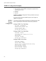
SNMPv3 Configuration Examples...................................................................................................................544
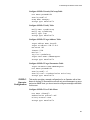
SNMPv3 Manager Configuration..............................................................................................................544
SNMPv3 Operator Configuration..............................................................................................................545
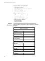
SNMPv3 Worksheet .................................................................................................................................546
Appendix C: Features and Standards ........................................................................................................549
10/100/1000Base-T Twisted Pair Ports ..........................................................................................................550
Denial of Service Defenses.............................................................................................................................550
Ethernet Protection Switching Ring Snooping ................................................................................................550
Fiber Optic Ports (AT-9408LC/SP Switch) ......................................................................................................551
File System .....................................................................................................................................................551
DHCP and BOOTP Clients .............................................................................................................................551
Internet Protocol Multicasting..........................................................................................................................551
Internet Protocol Version 4 Routing ................................................................................................................551
MAC Address Table ........................................................................................................................................552
Management Access and Security .................................................................................................................552
Management Access Methods........................................................................................................................553
Management Interfaces ..................................................................................................................................553
Management MIBs ..........................................................................................................................................553
Port Security ...................................................................................................................................................554
Port Trunking and Mirroring ............................................................................................................................554
Spanning Tree Protocols ................................................................................................................................554
System Monitoring ..........................................................................................................................................554
Traffic Control .................................................................................................................................................555
Virtual LANs ....................................................................................................................................................555
Virtual Router Redundancy Protocol...............................................................................................................556
12
AT-S63 Management Software Features Guide
Appendix D: MIB Objects ............................................................................................................................ 557
Access Control Lists ....................................................................................................................................... 558
Class of Service.............................................................................................................................................. 559
Date, Time, and SNTP Client ......................................................................................................................... 560
Denial of Service Defenses ............................................................................................................................ 561
Enhanced Stacking......................................................................................................................................... 562
GVRP ............................................................................................................................................................. 563
MAC Address Table ....................................................................................................................................... 565
Management Access Control List................................................................................................................... 566
Miscellaneous................................................................................................................................................. 567
Port Mirroring.................................................................................................................................................. 568
Quality of Service ........................................................................................................................................... 569
Port Configuration and Status ........................................................................................................................ 571
Spanning Tree ................................................................................................................................................ 572
Static Port Trunk............................................................................................................................................. 573
VLANs ............................................................................................................................................................ 574
Index ............................................................................................................................................................. 577
13
Contents
14
Figures
Figure 1: AT-StackXG Stacking Module ...............................................................................................................................67
Figure 2: Duplex-chain Topology..........................................................................................................................................70
Figure 3: Duplex-ring Topology ............................................................................................................................................71
Figure 4: Static Port Trunk Example...................................................................................................................................103
Figure 5: User Priority and VLAN Fields within an Ethernet Frame....................................................................................140
Figure 6: ToS field in an IP Header ....................................................................................................................................141
Figure 7: ACL Example 1 ...................................................................................................................................................151
Figure 8: ACL Example 2 ...................................................................................................................................................152
Figure 9: ACL Example 3 ...................................................................................................................................................153
Figure 10: ACL Example 4 .................................................................................................................................................154
Figure 11: ACL Example 5 .................................................................................................................................................154
Figure 12: ACL Example 6 .................................................................................................................................................155
Figure 13: DiffServ Domain Example .................................................................................................................................177
Figure 14: QoS Voice Application Example........................................................................................................................180
Figure 15: QoS Video Application Example........................................................................................................................182
Figure 16: QoS Critical Database Example ........................................................................................................................183
Figure 17: Policy Component Hierarchy Example ..............................................................................................................185
Figure 18: Group Link Control Example 1 ..........................................................................................................................190
Figure 19: Group Link Control Example 2 ..........................................................................................................................191
Figure 20: Group Link Control Example 3 ..........................................................................................................................192
Figure 21: Group Link Control Example 4 ..........................................................................................................................193
Figure 22: Group Link Control Example 5 ..........................................................................................................................194
Figure 23: Group Link Control Example 6 ..........................................................................................................................195
Figure 24: Group Link Control Example 7 ..........................................................................................................................196
Figure 25: IGMP Snooping Querier Example 1 ..................................................................................................................228
Figure 26: IGMP Snooping Querier Example 2 ..................................................................................................................229
Figure 27: SHOW IP INTERFACE Command ....................................................................................................................231
Figure 28: SHOW IGMPSNOOPING Command ................................................................................................................232
Figure 29: Double Fault Condition in EPSR Snooping .......................................................................................................248
Figure 30: MIB Tree............................................................................................................................................................258
Figure 31: SNMPv3 User Configuration Process ...............................................................................................................262
Figure 32: SNMPv3 Message Notification Process ............................................................................................................263
Figure 33: Point-to-Point Ports ...........................................................................................................................................277
Figure 34: Edge Port ..........................................................................................................................................................278
Figure 35: Point-to-Point and Edge Port.............................................................................................................................278
Figure 36: VLAN Fragmentation .........................................................................................................................................280
Figure 37: Loop Guard Example 1 .....................................................................................................................................284
Figure 38: Loop Guard Example 2 .....................................................................................................................................285
Figure 39: Loop Guard Example 3 .....................................................................................................................................285
Figure 40: Loop Guard Example 4 .....................................................................................................................................286
Figure 41: Loop Guard Example 5 .....................................................................................................................................287
Figure 42: VLAN Fragmentation with STP or RSTP...........................................................................................................293
Figure 43: MSTP Example of Two Spanning Tree Instances ............................................................................................294
Figure 44: Multiple VLANs in a MSTI..................................................................................................................................295
Figure 45: Multiple Spanning Tree Region .........................................................................................................................300
Figure 46: CIST and VLAN Guideline - Example 1.............................................................................................................305
Figure 47: CIST and VLAN Guideline - Example 2.............................................................................................................306
Figure 48: Spanning Regions - Example 1 .........................................................................................................................307
Figure 49: Port-based VLAN - Example 1 ..........................................................................................................................318
Figure 50: Port-based VLAN - Example 2 ..........................................................................................................................319
15
Figures
Figure 51: Example of a Tagged VLAN ..............................................................................................................................323
Figure 52: GVRP Example..................................................................................................................................................328
Figure 53: GARP Architecture ............................................................................................................................................334
Figure 54: GID Architecture ................................................................................................................................................335
Figure 55: Example of a MAC Address-based VLAN Spanning Switches..........................................................................355
Figure 56: Example of the Supplicant Role.........................................................................................................................428
Figure 57: Authenticator Port in Single Operating Mode with a Single Client.....................................................................430
Figure 58: Single Operating Mode with Multiple Clients Using the Piggy-back Feature - Example 1.................................431
Figure 59: Single Operating Mode with Multiple Clients Using the Piggy-back Feature - Example 2.................................432
Figure 60: Single Operating Mode with Multiple Clients Using the Piggy-back Feature - Example 3.................................433
Figure 61: Authenticator Port in Multiple Operating Mode - Example 1..............................................................................434
Figure 62: Authenticator Port in Multiple Operating Mode - Example 2..............................................................................435
Figure 63: SSH Remote Management of a Slave Switch ...................................................................................................485
16
Tables
Table 1: Basic Operations ...................................................................................................................................................34
Table 2: Advanced Operations ............................................................................................................................................35
Table 3: Snooping Protocols ...............................................................................................................................................36
Table 4: SNMPv3 ................................................................................................................................................................37
Table 5: Spanning Tree Protocols .......................................................................................................................................37
Table 6: Virtual LANs ...........................................................................................................................................................37
Table 7: Internet Protocol Routing .......................................................................................................................................38
Table 8: Port Security ..........................................................................................................................................................39
Table 9: Management Security ............................................................................................................................................39
Table 10: Management Interfaces .......................................................................................................................................41
Table 11: Management Interfaces for Basic Operations .....................................................................................................42
Table 12: Management Interfaces for Advanced Operations ..............................................................................................43
Table 13: Management Interfaces for Snooping Protocols ..................................................................................................44
Table 14: Management Interfaces for SNMPv3 ...................................................................................................................44
Table 15: Management Interfaces for Spanning Tree Protocols .........................................................................................44
Table 16: Management Interfaces for Virtual LANs .............................................................................................................45
Table 17: Management Interfaces for Internet Protocol Routing .........................................................................................45
Table 18: Management Interfaces for Port Security ............................................................................................................46
Table 19: Management Interfaces for Management Security ..............................................................................................46
Table 20: Twisted Pair Ports Matched with GBIC and SFP Slots ........................................................................................53
Table 21: New Features in AT-S63 Version 3.0.0 ...............................................................................................................58
Table 22: New Features in AT-S63 Version 2.1.0 ...............................................................................................................59
Table 23: New Features in AT-S63 Version 2.0.0 ...............................................................................................................59
Table 24: New Features in AT-S63 Version 1.3.0 ...............................................................................................................60
Table 25: New Features in AT-S63 Version 1.2.0 ...............................................................................................................61
Table 26: Support for AT-9400Ts Stacks ............................................................................................................................64
Table 27: Management Interfaces for AT-9400Ts Stacks ...................................................................................................64
Table 28: Maximum Number of Switches in a Stack of both 24-port and 48-port Switches ................................................68
Table 29: Support for Enhanced Stacking ...........................................................................................................................82
Table 30: Management Interfaces for Enhanced Stacking ..................................................................................................82
Table 31: Support for SNMPv1 and SNMPv2c Community Strings ....................................................................................92
Table 32: Management Interfaces for SNMPv1 and SNMPv2c Community Strings ...........................................................92
Table 33: Support for Static Port Trunks ...........................................................................................................................102
Table 34: Management Interfaces for Static Port Trunks ..................................................................................................102
Table 35: Support for LACP Port Trunks ...........................................................................................................................108
Table 36: Management Interfaces for LACP Port Trunks ..................................................................................................108
Table 37: Support for the Port Mirror .................................................................................................................................116
Table 38: Management Interfaces for the Port Mirror ........................................................................................................116
Table 39: Support for Link-flap Protection .........................................................................................................................120
Table 40: Management Interfaces for Link-flap Protection ................................................................................................120
Table 41: File Extensions and File Types ..........................................................................................................................129
Table 42: Support for the Event Logs and the Syslog Client .............................................................................................132
Table 43: Management Interfaces for the Event Logs and the Syslog Client ....................................................................132
Table 44: Support for Classifiers .......................................................................................................................................136
Table 45: Management Interfaces for Classifiers ..............................................................................................................136
Table 46: Support for the Access Control Lists .................................................................................................................146
Table 47: Management Interfaces for the Access Control Lists ........................................................................................146
Table 48: Support for the Class of Service Feature ...........................................................................................................158
Table 49: Management Interfaces for the Class of Service Feature .................................................................................158
17
Tables
Table 50: Default Mappings of IEEE 802.1p Priority Levels to Priority Queues ............................................................... 160
Table 51: Customized Mappings of IEEE 802.1p Priority Levels to Priority Queues ........................................................ 160
Table 52: Example of Weighted Round Robin Priority ...................................................................................................... 163
Table 53: Example of a Weight of Zero for Priority Queue 7 ............................................................................................ 163
Table 54: Support for Quality of Service ........................................................................................................................... 166
Table 55: Management Interfaces for Quality of Service .................................................................................................. 166
Table 56: Support for Group Link Control ......................................................................................................................... 188
Table 57: Management Interfaces for Group Link Control ................................................................................................ 188
Table 58: Link Control Groups on Switch 3 in Example 6 ................................................................................................. 195
Table 59: Link Control Groups on Switch 3 in Example 7 ................................................................................................. 196
Table 60: Support for the Denial of Service Defenses ...................................................................................................... 202
Table 61: Management Interfaces for the Denial of Service Defenses ............................................................................. 202
Table 62: Support for the Power Over Ethernet Feature .................................................................................................. 214
Table 63: Management Interfaces for the Power Over Ethernet Feature ......................................................................... 214
Table 64: Support for Internet Group Management Protocol Snooping ............................................................................ 222
Table 65: Management Interfaces for Internet Group Management Protocol Snooping .................................................. 222
Table 66: Support for IGMP Snooping Querier ................................................................................................................. 226
Table 67: Management Interfaces for IGMP Snooping Querier ........................................................................................ 226
Table 68: Support for Multicast Listener Discovery Snooping .......................................................................................... 236
Table 69: Management Interfaces for Multicast Listener Discovery Snooping ................................................................. 236
Table 70: Support for Router Redundancy Protocol Snooping ......................................................................................... 240
Table 71: Management Interfaces for Router Redundancy Protocol Snooping ................................................................ 240
Table 72: Support for Ethernet Protection Switching Ring Snooping ............................................................................... 244
Table 73: Management Interfaces for Ethernet Protection Switching Ring Snooping ...................................................... 244
Table 74: Support for SNMPv3 ......................................................................................................................................... 254
Table 75: Management Interfaces for the SNMPv3 .......................................................................................................... 254
Table 76: Support for the Spanning Tree and Rapid Spanning Tree Protocols ................................................................ 270
Table 77: Management Interfaces for the Spanning Tree and Rapid Spanning Tree Protocols ...................................... 270
Table 78: Bridge Priority Value Increments ...................................................................................................................... 272
Table 79: STP Auto-Detect Port Costs ............................................................................................................................. 273
Table 80: STP Auto-Detect Port Trunk Costs ................................................................................................................... 274
Table 81: RSTP Auto-Detect Port Costs ........................................................................................................................... 274
Table 82: RSTP Auto-Detect Port Trunk Costs ................................................................................................................ 274
Table 83: Port Priority Value Increments .......................................................................................................................... 275
Table 84: Support for the Multiple Spanning Tree Protocol .............................................................................................. 290
Table 85: Management Interfaces for the Multiple Spanning Tree Protocol ..................................................................... 290
Table 86: Support for Port-based and Tagged VLANs ..................................................................................................... 312
Table 87: Management Interfaces for Port-based and Tagged VLANs ............................................................................ 312
Table 88: Support for the GARP VLAN Registration Protocol .......................................................................................... 326
Table 89: Management Interfaces for the GARP VLAN Registration Protocol ................................................................. 326
Table 90: Support for the Multiple VLAN Modes ............................................................................................................... 338
Table 91: Management Interfaces for the Multiple VLAN Modes ..................................................................................... 338
Table 92: 802.1Q-Compliant Multiple VLAN Example ...................................................................................................... 340
Table 93: Support for Protected Ports VLANs .................................................................................................................. 344
Table 94: Management Interfaces for Protected Ports VLANs ......................................................................................... 344
Table 95: Support for MAC Address-based VLANs .......................................................................................................... 350
Table 96: Management Interfaces MAC Address-based VLANs ..................................................................................... 350
Table 97: Mappings of MAC Addresses to Egress Ports Example ................................................................................... 352
Table 98: Revised Example of Mappings of MAC Addresses to Egress Ports ................................................................. 353
Table 99: Example of a MAC Address-based VLAN Spanning Switches ......................................................................... 356
Table 100: Support for IPv4 Packet Routing ..................................................................................................................... 364
Table 101: Management Interfaces for IPv4 Packet Routing ........................................................................................... 364
Table 102: ICMP Messages Implemented on the AT-9400 Switch .................................................................................. 382
Table 103: IPv4 Routing Example .................................................................................................................................... 390
Table 104: Support for the BOOTP Relay Agent .............................................................................................................. 398
Table 105: Management Interfaces for the BOOTP Relay Agent .................................................................................... 398
Table 106: Support for the Virtual Router Redundancy Protocol ...................................................................................... 404
Table 107: Management Interfaces for the Virtual Router Redundancy Protocol ............................................................. 404
Table 108: Support for MAC Address-based Port Security .............................................................................................. 416
Table 109: Management Interfaces for MAC Address-based Port Security ..................................................................... 416
18
AT-S63 Management Software Features Guide
Table 110: Support for 802.1x Port-based Network Access Control .................................................................................422
Table 111: Management Interfaces for 802.1x Port-based Network Access Control ........................................................422
Table 112: Support for the Web Server .............................................................................................................................448
Table 113: Management Interfaces for the Web Server ....................................................................................................448
Table 114: Support for Encryption Keys ............................................................................................................................454
Table 115: Management Interfaces for Encryption Keys ...................................................................................................454
Table 116: Support for PKI Certificates and SSL ..............................................................................................................464
Table 117: Management Interfaces for PKI Certificates and SSL .....................................................................................464
Table 118: Support for the Secure Shell Protocol .............................................................................................................480
Table 119: Management Interfaces for the Secure Shell Protocol ...................................................................................480
Table 120: Support for the TACACS+ and RADIUS Protocols ..........................................................................................490
Table 121: Management Interfaces for the TACACS+ and RADIUS Protocols ...............................................................490
Table 122: Support for the Management Access Control List ...........................................................................................498
Table 123: Management Interfaces for the Management Access Control List .................................................................498
Table 124: Access Control Lists (AtiStackSwitch MIB) ......................................................................................................558
Table 125: CoS Scheduling (AtiStackSwitch MIB) ............................................................................................................559
Table 126: CoS Priority to Egress Queue Mappings (AtiStackSwitch MIB) ......................................................................559
Table 127: CoS Packet Weights of Egress Queues (AtiStackSwitch MIB) .......................................................................559
Table 128: CoS Port Settings (AtiStackSwitch MIB) ..........................................................................................................559
Table 129: Date, Time, and SNTP Client (AtiStackSwitch MIB) ........................................................................................560
Table 130: LAN Address and Subnet Mask (AtiStackSwitch MIB) ....................................................................................561
Table 131: Denial of Service Defenses (AtiStackSwitch MIB) ...........................................................................................561
Table 132: Switch Mode and Discovery (AtiStackInfo MIB) ..............................................................................................562
Table 133: Switches of an Enhanced Stack (AtiStackInfo MIB) ........................................................................................562
Table 134: GVFP Switch Configuration (AtiStackSwitch MIB) ..........................................................................................563
Table 135: GVRP Port Configuration (AtiStackSwitch MIB) ..............................................................................................563
Table 136: GVRP Counters (AtiStackSwitch MIB) ............................................................................................................563
Table 137: MAC Address Table (AtiStackSwitch MIB) ......................................................................................................565
Table 138: Static MAC Address Table (AtiStackSwitch MIB) ............................................................................................565
Table 139: Management Access Control List Status (AtiStackSwitch MIB) ......................................................................566
Table 140: Management Access Control List Entries (AtiStackSwitch MIB) .....................................................................566
Table 141: System Reset (AtiStackSwitch MIB) ................................................................................................................567
Table 142: Local Interface (AtiStackSwitch MIB) ...............................................................................................................567
Table 143: Saving the Configuration and Returning to Default Settings (AtiStackSwitch MIB) .........................................567
Table 144: Port Mirroring (AtiStackSwitch MIB) ................................................................................................................568
Table 145: Flow Groups (AtiStackSwitch MIB) ..................................................................................................................569
Table 146: Traffic Classes (AtiStackSwitch MIB) ..............................................................................................................569
Table 147: Policies (AtiStackSwitch MIB) ..........................................................................................................................570
Table 148: Port Configuration and Status (AtiStackSwitch MIB) ......................................................................................571
Table 149: Spanning Tree (AtiStackSwitch MIB) ...............................................................................................................572
Table 150: Static Port Trunks (AtiStackSwitch MIB) .........................................................................................................573
Table 151: VLAN Table (AtiStackSwitch MIB) ...................................................................................................................574
Table 152: VLAN Table (AtiStackSwitch MIB) ...................................................................................................................574
Table 153: VLAN Mode and Uplink Port (AtiStackSwitch MIB) .........................................................................................574
Table 154: PVID Table (AtiStackSwitch MIB) ....................................................................................................................575
19
Tables
20
Preface
This guide describes the features of the AT-9400 Layer 2+ and Basic
Layer 3 Gigabit Ethernet Switches and the AT-S63 Management Software.
This preface contains the following sections:
“How This Guide is Organized” on page 22
“Product Documentation” on page 25
“Where to Go First” on page 26
“Starting a Management Session” on page 27
“Document Conventions” on page 28
“Contacting Allied Telesis” on page 29
Caution
The software described in this documentation contains certain
cryptographic functionality and its export is restricted by U.S. law. As
of this writing, it has been submitted for review as a “retail encryption
item” in accordance with the Export Administration Regulations, 15
C.F.R. Part 730-772, promulgated by the U.S. Department of
Commerce, and conditionally may be exported in accordance with
the pertinent terms of License Exception ENC (described in 15
C.F.R. Part 740.17). In no case may it be exported to Cuba, Iran,
Iraq, Libya, North Korea, Sudan, or Syria. If you wish to transfer this
software outside the United States or Canada, please contact your
local Allied Telesis sales representative for current information on
this product’s export status.
21
Preface
How This Guide is Organized
This guide has the following sections and chapters:
Section I: Basic Operations
Chapter 1, “Overview” on page 33
Chapter 2, “AT-9400Ts Stacks” on page 63
Chapter 3, “Enhanced Stacking” on page 81
Chapter 4, “SNMPv1 and SNMPv2c” on page 91
Chapter 5, “MAC Address Table” on page 97
Chapter 6, “Static Port Trunks” on page 101
Chapter 7, “LACP Port Trunks” on page 107
Chapter 8, “Port Mirror” on page 115
Chapter 9, “Link-flap Protection” on page 119
Section II: Advanced Operations
Chapter 10, “File System” on page 127
Chapter 11, “Event Logs and the Syslog Client” on page 131
Chapter 12, “Classifiers” on page 135
Chapter 13, “Access Control Lists” on page 145
Chapter 14, “Class of Service” on page 157
Chapter 15, “Quality of Service” on page 165
Chapter 16, “Group Link Control” on page 187
Chapter 17, “Denial of Service Defenses” on page 201
Chapter 18, “Power Over Ethernet” on page 213
Section III: Snooping Protocols
Chapter 19, “Internet Group Management Protocol Snooping” on page
221
Chapter 20, “Internet Group Management Protocol Snooping Querier”
on page 225
Chapter 21, “Multicast Listener Discovery Snooping” on page 235
Chapter 22, “Router Redundancy Protocol Snooping” on page 239
22
AT-S63 Management Software Features Guide
Chapter 23, “Ethernet Protection Switching Ring Snooping” on page
243
Section IV: SNMPv3
Chapter 24, “SNMPv3” on page 253
Section V: Spanning Tree Protocols
Chapter 25, “Spanning Tree and Rapid Spanning Tree Protocols” on
page 269
Chapter 26, “Multiple Spanning Tree Protocol” on page 289
Section VI: Virtual LANs
Chapter 27, “Port-based and Tagged VLANs” on page 311
Chapter 28, “GARP VLAN Registration Protocol” on page 325
Chapter 29, “Multiple VLAN Modes” on page 337
Chapter 30, “Protected Ports VLANs” on page 343
Chapter 31, “MAC Address-based VLANs” on page 349
Section VII: Routing
Chapter 32, “Internet Protocol Version 4 Packet Routing” on page 363
Chapter 33, “BOOTP Relay Agent” on page 397
Chapter 34, “Virtual Router Redundancy Protocol” on page 403
Section VIII: Port Security
Chapter 35, “MAC Address-based Port Security” on page 415
Chapter 36, “802.1x Port-based Network Access Control” on page 421
Section IX: Management Security
Chapter 37, “Web Server” on page 447
Chapter 38, “Encryption Keys” on page 453
Chapter 39, “PKI Certificates and SSL” on page 463
Chapter 40, “Secure Shell (SSH)” on page 479
Chapter 41, “TACACS+ and RADIUS Protocols” on page 489
Chapter 42, “Management Access Control List” on page 497
Appendices
Appendix A, “AT-S63 Management Software Default Settings” on page
505
23
Preface
Appendix B, “SNMPv3 Configuration Examples” on page 543
Appendix C, “Features and Standards” on page 549
Appendix D, “MIB Objects” on page 557
24
AT-S63 Management Software Features Guide
Product Documentation
For overview information on the features of the AT-9400 Switches and the
AT-S63 Management Software, refer to:
AT-S63 Management Software Features Guide
(PN 613-001022)
For instructions on how to start a local or remote management session on
stand-alone AT-9400 Switches or AT-9400Ts Stacks, refer to:
Starting an AT-S63 Management Session Guide
(PN 613-001023)
For instructions on how to install or manage stand-alone AT-9400
Switches, refer to:
AT-9400 Gigabit Ethernet Switch Installation Guide
(PN 613-000987)
AT-S63 Management Software Menus User’s Guide
(PN 613-001025)
AT-S63 Management Software Command Line User’s Guide
(PN 613-001024)
AT-S63 Management Software Web Browser User’s Guide
(PN 613-001026)
For instructions on how to install or manage AT-9400Ts Stacks, refer to:
AT-9400Ts Stack Installation Guide
(PN 613-001191
AT-S63 Management Software Command Line User’s Guide
(PN 613-001024)
AT-S63 Management Software Web Browser User’s Guide for
AT-9400Ts Stacks
(PN 613-001028)
The installation and user guides for all the Allied Telesis products are
available in portable document format (PDF) on our web site at
www.alliedtelesis.com. You can view the documents online or download
them onto a local workstation or server.
25
Preface
Where to Go First
Allied Telesis recommends that you read Chapter 1, “Overview” on page
33 in this guide before you begin to manage the switch for the first time.
There you will find a variety of basic information about the unit and the
management software, like the two levels of manager access levels and
the different types of management sessions. You should also read
Chapter 2, “AT-9400Ts Stacks” on page 63 if you are managing a stack of
the AT-9424Ts, AT-9424Ts/XP and AT-9448Ts/XP Switches.
This guide is your resource for background information on the features of
the switch. You can refer here for the relevant concepts and guidelines
when you configure a feature for the first time.
26
AT-S63 Management Software Features Guide
Starting a Management Session
For instructions on how to start a local or remote management session on
the AT-9400 Switch, refer to the Starting an AT-S63 Management Session
Guide.
27
Preface
Document Conventions
This document uses the following conventions:
Note
Notes provide additional information.
Caution
Cautions inform you that performing or omitting a specific action
may result in equipment damage or loss of data.
Warning
Warnings inform you that performing or omitting a specific action
may result in bodily injury.
28
AT-S63 Management Software Features Guide
Contacting Allied Telesis
This section provides Allied Telesis contact information for technical
support and for sales and corporate information.
Online Support
You can request technical support online by accessing the Allied Telesis
Knowledge Base: www.alliedtelesis.com/support/kb.aspx. You can use
the Knowledge Base to submit questions to our technical support staff and
review answers to previously asked questions.
Email and
Telephone
Support
For Technical Support via email or telephone, refer to the Allied Telesis
web site at www.alliedtelesis.com. Select your country from the list on
the web site and then select the appropriate tab.
Returning
Products
Products for return or repair must first be assigned a return materials
authorization (RMA) number. A product sent to Allied Telesis without an
RMA number will be returned to the sender at the sender’s expense. For
instructions on how to obtain an RMA number, go to the Support section
on our web site at www.alliedtelesis.com.
Sales or
Corporate
Information
You can contact Allied Telesis for sales or corporate information through
our web site at www.alliedtelesis.com.
Management
Software Updates
New releases of the management software for our managed products are
available from the following Internet sites:
Allied Telesis web site: www.alliedtelesis.com
Allied Telesis FTP server: ftp://ftp.alliedtelesis.com
If the FTP server prompts you to log on, enter “anonymous” as the user
name and your email address as the password.
29
Preface
30
Section I
Basic Operations
The chapters in this section contain background information on basic
switch features. The chapters include:
Section I: Basic Operations
Chapter 1, “Overview” on page 33
Chapter 2, “AT-9400Ts Stacks” on page 63
Chapter 3, ”Enhanced Stacking” on page 81
Chapter 4, ”SNMPv1 and SNMPv2c” on page 91
Chapter 5, ”MAC Address Table” on page 97
Chapter 6, ”Static Port Trunks” on page 101
Chapter 7, “LACP Port Trunks” on page 107
Chapter 8, ”Port Mirror” on page 115
Chapter 9, “Link-flap Protection” on page 119
31
32
Section I: Basic Operations
Chapter 1
Overview
This chapter has the following sections:
“Layer 2+ and Basic Layer 3 Switches” on page 34
“AT-S63 Management Software” on page 40
“Management Interfaces” on page 41
“Management Access Methods” on page 47
“Manager Access Levels” on page 49
“Installation and Management Configurations” on page 50
“IP Configuration” on page 51
“Configuration Files” on page 52
“Redundant Twisted Pair Ports” on page 53
“History of New Features” on page 55
33
Chapter 1: Overview
Layer 2+ and Basic Layer 3 Switches
The switches in the AT-9400 Gigabit Ethernet Series are divided into two
groups:
Layer 2+ Switches
— AT-9408LC/SP
— AT-9424T/GB
— AT-9424T/SP
Basic Layer 3 Switches
— AT-9424T
— AT-9424T/POE
— AT-9424Ts
— AT-9424Ts/XP
— AT-9448T/SP
— AT-9448Ts/XP
Although the switches have many of the same features and capabilities,
there are a number of significant differences. For instance, the Internet
Protocol Version 4 packet routing feature is only supported on the Basic
Layer 3 switches and is the reason for the group’s name.
The following tables list the supported features on the various switches.
The Stack column lists the features of the AT-9424Ts, AT-9424Ts/XP, and
AT-9448Ts/XP Switches when installed as AT-9400Ts Stacks with the
AT-StackXG Stacking Module.
(Y = supported features)
Table 1. Basic Operations
Layer 2+ Switches
08LC 24GB 24SP
Basic Layer 3 Switches
24T
24T
POE
24Ts 24XP 48SP 48XP
Stack
Local management
Y
Y
Y
Y
Y
Y
Y
Y
Y
Y
Remote Telnet
management
Y
Y
Y
Y
Y
Y
Y
Y
Y
Y
Remote Secure Shell
management
Y
Y
Y
Y
Y
Y
Y
Y
Y
Y
Remote web browser
management
Y
Y
Y
Y
Y
Y
Y
Y
Y
Y
34
AT-S63 Management Software Features Guide
Table 1. Basic Operations
Layer 2+ Switches
08LC 24GB 24SP
Multiple manager
sessions
Basic Layer 3 Switches
24T
24T
POE
Y
Y
Y
Y
Y
Y
Y
Y
24Ts 24XP 48SP 48XP
Stack
TCP/IP pings
Y
Y
Y
Y
Y
Y
Y
Y
Y
Enhanced stacking
Y
Y
Y
Y
Y
Y
Y
Y
Y
Simple Network Time
Protocol (SNTP)
Y
Y
Y
Y
Y
Y
Y
Y
Y
SNMPv1 and
SNMPv2
Y
Y
Y
Y
Y
Y
Y
Y
Y
Y
Packet filtering
Y
Y
Y
Y
Y
Y
Y
Y
Y
Y
Packet rate limiting
Y
Y
Y
Y
Y
Y
Y
Y
Y
Y
Port statistics
Y
Y
Y
Y
Y
Y
Y
Y
Y
Y
Static port trunks
Y
Y
Y
Y
Y
Y
Y
Y
Y
Y
Link Aggregation
Control Protocol
(LACP) trunks
Y
Y
Y
Y
Y
Y
Y
Y
Y
Y
Port mirroring
Y
Y
Y
Y
Y
Y
Y
Y
Y
Y
Y
Y
Y
Y
Y
Y
Y
Link flap protection
Table 2. Advanced Operations
Layer 2+ Switches
08LC 24GB 24SP
Basic Layer 3 Switches
24T
24T
POE
24Ts 24XP 48SP 48XP
Stack
File system
Y
Y
Y
Y
Y
Y
Y
Y
Y
Y1
Event logs
Y
Y
Y
Y
Y
Y
Y
Y
Y
Y2
TFTP client
Y
Y
Y
Y
Y
Y
Y
Y
Y
Y
Syslog client
Y
Y
Y
Y
Y
Y
Y
Y
Y
Y
Classifiers
Y
Y
Y
Y
Y
Y
Y
Y
Y
Y
Access control lists
Y
Y
Y
Y
Y
Y
Y
Y
Y
Y
35
Chapter 1: Overview
Table 2. Advanced Operations
Layer 2+ Switches
08LC 24GB 24SP
Basic Layer 3 Switches
24T
24T
POE
24Ts 24XP 48SP 48XP
Stack
Class of Service
Y
Y
Y
Y
Y
Y
Y
Y
Y
Y
Quality of Service
Y
Y
Y
Y
Y
Y
Y
Y
Y
Y
Y
Y
Y
Y
Y
Y
Y
Y
Y
Y
Y
Y
Y
Group link control
Denial of service
defenses
Y
Y
Y
Power over Ethernet
Y
1. The only accessible file system in a stack is the one on the master switch.
2. The only active event logs in a stack are the ones on the master switch.
Table 3. Snooping Protocols
Layer 2+ Switches
08LC 24GB 24SP
Internet Group
Management
Protocol (IGMP)
snooping
Y
Y
Y
IGMP snooping
querier
Basic Layer 3 Switches
24T
24T
POE
Y
Y
Y
Y
Y
Y
Y
Y
Y
Y
Y
Y
Y
Y
24Ts 24XP 48SP 48XP
Multicast Listener
Discovery (MLD)
snooping
Y
Y
Y
Y
Y
Y
Y
Y
Y
Router Redundancy
Protocol (RRP)
snooping
Y
Y
Y
Y
Y
Y
Y
Y
Y
Y
Y
Y
Y
Y
Y
Ethernet Protection
Switching Ring
(EPSR) snooping
36
Stack
AT-S63 Management Software Features Guide
Table 4. SNMPv3
Layer 2+ Switches
08LC 24GB 24SP
SNMPv3
Y
Y
Y
Basic Layer 3 Switches
24T
24T
POE
Y
Y
24Ts 24XP 48SP 48XP
Y
Y
Y
Y
Stack
Y
Table 5. Spanning Tree Protocols
Layer 2+ Switches
08LC 24GB 24SP
Basic Layer 3 Switches
24T
24T
POE
24Ts 24XP 48SP 48XP
Stack
Spanning Tree
Protocol (STP)
Y
Y
Y
Y
Y
Y
Y
Y
Y
Y
Rapid Spanning Tree
Protocol (RSTP)
Y
Y
Y
Y
Y
Y
Y
Y
Y
Y
RSTP loop guard
Y
Y
Y
Y
Y
Y
Y
RSTP BPDU guard
Y
Y
Y
Y
Y
Y
Y
Y
Y
Y
Y
Y
Y
Multiple Spanning
Tree Protocol
(MSTP)
Y
Y
Y
Table 6. Virtual LANs
Layer 2+ Switches
08LC 24GB 24SP
Basic Layer 3 Switches
24T
24T
POE
24Ts 24XP 48SP 48XP
Port-based and
tagged VLANs
Y
Y
Y
Y
Y
Y
Y
Y
Y
802.1Q-compliant
and
non-802.1Qcompliant multiple
VLAN modes
Y
Y
Y
Y
Y
Y
Y
Y
Y
Stack
Y
37
Chapter 1: Overview
Table 6. Virtual LANs
Layer 2+ Switches
08LC 24GB 24SP
Basic Layer 3 Switches
24T
24T
POE
24Ts 24XP 48SP 48XP
GARP VLAN
Registration Protocol
Y
Y
Y
Y
Y
Y
Y
Y
Y
Protected ports
VLANs
Y
Y
Y
Y
Y
Y
Y
Y
Y
Y
Y
Y
Y
Y
Y
MAC address-based
VLANs
Stack
Table 7. Internet Protocol Routing
Layer 2+ Switches
Basic Layer 3 Switches
24T
24T
POE
Static routes for
Internet Protocol
version 4 routing
Y
Y
Y
Y
Y
Y
Routing Information
Protocol (RIP)
Y
Y
Y
Y
Y
Y
Y
Y
Y
Y
Y
Y
Y
Y
Y
Y
Y
Y
Y
Y
Y
Y
Y
Y
Y
Y
Y
Y
Y
Y
Y
Y
08LC 24GB 24SP
One routing
interface1
Y
Y
Y
Virtual Router
Redundancy
Protocol
BOOTP and DHCP
clients
BOOTP relay agent
Y
Y
Y
1. Used to assign the switch or stack an IP address configuration.
38
24Ts 24XP 48SP 48XP
Stack
Y
Y
AT-S63 Management Software Features Guide
Table 8. Port Security
Layer 2+ Switches
08LC 24GB 24SP
Basic Layer 3 Switches
24T
24T
POE
24Ts 24XP 48SP 48XP
Stack
MAC address-based
port security
Y
Y
Y
Y
Y
Y
Y
Y
Y
Y
802.1x port-based
network access
control using
RADIUS protocol
Y
Y
Y
Y
Y
Y
Y
Y
Y
Y
Table 9. Management Security
Layer 2+ Switches
08LC 24GB 24SP
Basic Layer 3 Switches
24T
24T
POE
24Ts 24XP 48SP 48XP
Stack
Encryption keys
Y
Y
Y
Y
Y
Y
Y
Y
Y
Y
Public Key
Infrastructure (PKI)
certificates and
Secure Sockets
Layer (SSL) protocol
Y
Y
Y
Y
Y
Y
Y
Y
Y
Y
Remote Secure Shell
management
Y
Y
Y
Y
Y
Y
Y
Y
Y
Y
Manager accounts
using TACACS+ or
RADIUS protocol
Y
Y
Y
Y
Y
Y
Y
Y
Y
Y1
Management access
control list
Y
Y
Y
Y
Y
Y
Y
Y
Y
1. Stacks do not support the TACACS+ protocol. You can use the web browser interface to configure RADIUS
accounting on a stack, but you cannot use the interface to enter the IP addresses of the RADIUS servers.
39
Chapter 1: Overview
AT-S63 Management Software
The AT-9400 Switch is managed with the AT-S63 Management Software.
The software comes preinstalled on the unit with default settings for all the
operating parameters of the switch. If the default settings are adequate for
your network, you can use the switch as an unmanaged unit.
Note
The default settings are listed in Appendix A, “AT-S63 Management
Software Default Settings” on page 505.
You can access the management software on the switch several different
ways. You can manage the switch locally (out-of-band) using the Terminal
Port on the front panel or over a network (in-band) using a Telnet or
Secure Shell client, or a web browser. For further information, refer to
“Management Access Methods” on page 47.
The management software has four management interfaces -- a menus
interface, a standard command line interface, an AlliedWare Plus
command line interface, and a web browser interface. You can use any of
the interfaces to perform basic configuration procedures. But some of the
newer and more complex features, such as Virtual Router Redundancy
Protocol (VRRP), must be configured with the standard command line
interface or the AlliedWare Plus command line interface. For more
information, refer to “Management Interfaces” on page 41.
There are two current versions of the management software. Version 2.2.0
is for the Layer 2+ switches and Version 4.1.0 is for the Basic Layer 3
switches.
Note
Do not install version 4.1.0 on a Layer 2+ switch.
40
AT-S63 Management Software Features Guide
Management Interfaces
The AT-S63 Management Software has four management interfaces:
Standard command line
AlliedWare Plus command line
Menus
Web browser windows
As shown in Table 10, the standard command line and the web browser
windows are supported on all of the possible platforms: stand-alone
AT-9400 Layer 2+ Switches, stand-alone AT-9400 Basic Layer 3
Switches, and AT-9400 Stacks. The AlliedWare Plus command line is not
supported on the AT-9400 Layer 2+ Switches and the menus interface is
not supported on AT-9400Ts Stacks.
Table 10. Management Interfaces
Standard
Command
Line
AlliedWare
Plus
Command
Line
AT-9400
Layer 2+
Switches
Y
AT-9400
Basic Layer
3 Switches
Y
Y
AT-9400Ts
Stacks
Y
Y
Menus
Web
Browser
Windows
Y
Y
Y
Y
Y
You can access the standard command line, the AlliedWare Plus
command line and the menus from local management sessions and from
remote Telnet and Secure Shell clients. The web browser windows are
available from remote web browsers using either non-secure HTTP or
secure HTTPS.
The standard command line is the only management interface that lets you
configure all of the parameters on stand-alone switches and stacks. The
other management interfaces support only a subset of the management
functions. For instance, you can use any of the management interfaces to
configure the basic settings of the ports (e.g., speeds and duplex modes),
but you have to use the standard command line to configure MAC
address-based VLANs.
41
Chapter 1: Overview
In other cases, a management interface might support only part of a
function. For example, you can set a switch or stack’s name, contact or
location with any of the management interfaces, except for the AlliedWare
Plus commands, which only lets you set the name.
The following tables list the features you can configure from the various
management interfaces for stand-alone switches and AT-9400Ts Stacks.
The acronyms are as follows:
SCL - Standard Command Line
ACL - AlliedWare Plus Command Line
M - Menus
WB - Web browser
Table 11. Management Interfaces for Basic Operations
Stand-alone Switches
42
Stacks
SCL
ACL
M
WB
SCL
ACL
WB
Switch’s name, location, and
contact
Y
Y1
Y
Y
Y
Y1
Y
Manager and operator passwords
Y
Y
Y
Y
Date and time (manual and SNTP)
Y
Y
Y
Y
Y
Y
Rebooting a switch
Y
Y
Y
Y
Y
Y
Multiple manager sessions
Y
Y
Y
Y
TCP/IP pings
Y
Y
Y
Y
Enhanced stacking
Y
Y
Y
Y
Y
Y
Y
SNMPv1 and SNMPv2
community strings
Y
Y
Y
Y
Port parameters
Y
Y
Y
Y
Y
Y
Y
Port statistics
Y
Y
Y
Y
Y
Y
Y
MAC address table
Y
Y
Y
Y
Y
Y
Y
Static MAC addresses
Y
Y
Y
Y
Y
Y
Y
Static port trunks
Y
Y
Y
Y
Y
Y
Y
Link Aggregation Control Protocol
(LACP) trunks
Y
Y
Y
Y
Y
Port mirroring
Y
Y
Y
Y
Y
Link-flap protection
Y
Y
Y
Y
Y
Y
Y
Y
AT-S63 Management Software Features Guide
Table 11. Management Interfaces for Basic Operations
Stand-alone Switches
SCL
ACL
M
Baud rate of the Terminal Port
Y
Y
Management console timer
Y
Telnet server
Y
Console startup mode
Y
WB
Stacks
SCL
ACL
Y
Y
Y
Y
Y
Y
Y
Y
Y
Y
Y
Y
Y
WB
1. You can use the AlliedWare Plus command line to set the name of the switch or stack, but not the
contact or location.
Table 12. Management Interfaces for Advanced Operations
Stand-alone Switches
Stacks
SCL
ACL
M
WB
SCL
ACL
WB
File system and configuration files
Y
Y
Y
Y1
Y
Y
Y2
Format flash memory
Y
File uploads and downloads
Y
Event logs
Y
Y
Y4
Y
Y5
Y
Y
Y6
Y
Y6
Syslog client
Y
Y
Y
Y
Y
Classifiers
Y
Y
Y
Y
Y
Y
Access control lists
Y
Y
Y
Y
Y
Y
Class of Service
Y
Y
Y
Y
Quality of Service
Y
Y
Y
Y
Y
Denial of service defenses
Y
Y
Y
Group link control
Y
Y
Y
Power over Ethernet
Y
Y3
Y
Y
Y
1. You can use the web browser windows to view the files in the file system of a switch or on a
compact flash card, but you cannot: copy, rename, or delete them; change directories on a
compact flash card; or create a new switch configuration file.
2. You can use the web browser windows to view the files in the file system of the master switch or
on a compact flash card in the master switch, but you cannot: copy, rename, or delete files;
change directories on a compact flash card; or create a new switch configuration file.
3. You can use the AlliedWare Plus command line to download new versions of the AT-S63
Management Software to stand-alone switches. You cannot use this interface to download new
versions of the management software to stacks or to transfer files to the file system.
43
Chapter 1: Overview
4. You cannot upload or download files to a compact flash card with the web browser windows.
Also, that interface does not support switch-to-switch uploads.
5. You cannot upload or download files to a compact flash card with the web browser interface.
6. You cannot modify the event log full action from the web browser windows.
Table 13. Management Interfaces for Snooping Protocols
Stand-alone Switches
Stacks
SCL
ACL
M
WB
SCL
ACL
WB
Internet Group Management
Protocol (IGMP) snooping
Y
Y
Y
Y
Y
Y
Y
IGMP snooping querier
Y
Y
Y
Y
Multicast Listener Discovery
(MLD) snooping
Y
Y
Y
Router Redundancy Protocol
(RRP) snooping
Y
Y
Y
Ethernet Protection Switching
Ring (EPSR) snooping
Y
Table 14. Management Interfaces for SNMPv3
Stand-alone Switches
SNMPv3
Stacks
SCL
ACL
M
WB
SCL
ACL
WB
Y
Y
Y
Y
Y
Y
Y
Table 15. Management Interfaces for Spanning Tree Protocols
Stand-alone Switches
44
Stacks
SCL
ACL
M
WB
SCL
ACL
WB
Spanning Tree Protocol (STP)
Y
Y
Y
Y
Y
Y
Y
Rapid Spanning Tree Protocol
(RSTP)
Y
Y
Y
Y
Y
Y
Y
RSTP loop guard
Y
Y
Y
Y
Y
RSTP BPDU guard
Y
Y
Y
Y
Y
AT-S63 Management Software Features Guide
Table 15. Management Interfaces for Spanning Tree Protocols
Stand-alone Switches
Multiple Spanning Tree Protocol
(MSTP)
SCL
ACL
M
WB
Y
Y
Y
Y
Stacks
SCL
ACL
WB
Table 16. Management Interfaces for Virtual LANs
Stand-alone Switches
Stacks
SCL
ACL
M
WB
SCL
ACL
WB
Port-based and tagged VLANs
Y
Y
Y
Y
Y
Y
Y
802.1Q-compliant and
non-802.1Q-compliant multiple
VLAN modes
Y
Y
Y
GARP VLAN Registration Protocol
Y
Y
Y
Protected ports VLANs
Y
Y
MAC address-based VLANs
Y
Y
Y
Table 17. Management Interfaces for Internet Protocol Routing
Stand-alone Switches
SCL
ACL
M
Routing interfaces
Y
Y
Y
Static routes
Y
Y
Routing Information Protocol (RIP)
Y
Y
Address Resolution Protocol
(ARP) table
Y
BOOTP and DHCP clients
Y
BOOTP relay agent
Y
Virtual Router Redundancy
Protocol
Y
WB
Stacks
SCL
ACL
Y
Y
Y
Y
WB
Y
Y
Y
Y
Y
Y
Y
45
Chapter 1: Overview
Table 18. Management Interfaces for Port Security
Stand-alone Switches
Stacks
SCL
ACL
M
WB
SCL
ACL
MAC address-based port security
Y
Y
Y
Y
Y
Y
802.1x port-based network access
control
Y
Y
Y
Y
Y
Y
WB
Y
Table 19. Management Interfaces for Management Security
Stand-alone Switches
SCL
ACL
M
Web server
Y
Y1
Y
Encryption keys
Y
Y
Y
Public Key Infrastructure (PKI)
certificates and Secure Sockets
Layer (SSL) protocol
Y
Secure Shell server
Y
TACACS+ and RADIUS
authentication
Y
Management access control list
Y
WB
Stacks
SCL
ACL
Y
Y1
Y2
Y
Y
Y
Y3
Y
Y
Y
Y
Y
Y
Y
Y
Y
Y
Y
Y
Y
WB
1. You can use the AlliedWare Plus command line to enable or disable the web server. To configure
the server you have to use another management interface.
2. From the web browser interface you can view the encryption keys, but you cannot create or
delete them.
3. You can use the web browser interface to view the PKI certificates and the SSL and PKI settings.
You cannot create or delete certificates or certificate enrollment requests, or change the settings.
46
AT-S63 Management Software Features Guide
Management Access Methods
You can access the AT-S63 Management Software on a switch several
ways:
Local
Management
Sessions
Local session
Remote Telnet session
Remote Secure Shell (SSH) session
Remote web browser (HTTP or HTTPS) session
Remote SNMP session
To establish a local management session, you connect a terminal or a PC
with a terminal emulator program to the Terminal Port on the front panel of
the stand-alone switch or the master switch of a stack. This type of
management session, which uses the management cable included with
the unit, must be performed at the switch, hence the name “local.”
A switch or stack does not require an Internet Protocol (IP) configuration
for local management.
Here are the management interfaces that are available to you from this
type of management session:
Standard command line
AlliedWare Plus command line
Menus
You can change between the interfaces during your management
sessions.
Note
In most cases, the initial management session of a switch must be a
local management session.
Remote Telnet
Sessions
The AT-S63 Management Software comes with a Telnet server for remote
management of the unit from Telnet clients on your network. You can use
these management interfaces from remote Telnet management sessions:
Standard command line
AlliedWare Plus command line
Menus
47
Chapter 1: Overview
Remote Secure
Shell (SSH)
Sessions
The AT-S63 Management Software also has a Secure Shell (SSH) server
for remote management from SSH clients on your network. An SSH
management session is similar to a Telnet management session except it
uses encryption to protect the session from snooping.
Here are the management interfaces available to you from remote SSH
management sessions:
Remote Web
Browser Session
Remote SNMP
Management
Standard command line
AlliedWare Plus command line
Menus
The AT-S63 Management Software also comes with a web browser server
and a web browser interface for remote management using a web browser
at a workstation on your network. A web browser session can be either
non-encrypted (HTTP) or encrypted (HTTPS).
You can also remotely configure the switch using a Simple Network
Management Protocol (SNMP) application, such as AT-View. This
management method requires an understanding of management
information base (MIB) objects.
The AT-S63 Management Software supports the following MIBs:
SNMP MIB-II (RFC 1213)
Bridge MIB (RFC 1493)
Interface Group MIB (RFC 2863)
Ethernet MIB (RFC 1643)
Remote Network MIB (RFC 1757)
Allied Telesis managed switch MIBs
The Allied Telesis managed switch MIBs (atistackinfo.mib and
atistackswitch.mib) are available from the Allied Telesis web site.
Note
The switch must have an IP address for remote Telnet, SSH, or
SNMP management. For background information, refer to “IP
Configuration” on page 51.
48
AT-S63 Management Software Features Guide
Manager Access Levels
The AT-S63 Management Software has two manager access levels of
manager and operator. The manager access level lets you view and
configure the operating parameters, while the operator access level lets
you only view the parameters settings.
You log in by entering the appropriate username and password when you
start a management session. To log in as a manager, type “manager” as
the login name. The default password is “friend.” The username for
operator is “operator” and the default password is also “operator.” The
usernames and passwords are case sensitive.
There can be up to three active manager sessions at a time on a switch.
This is set with the SET SYSTEM command in the command line
interface. The default is just one manager session.
There can be up to nine operator sessions if there are no active manager
sessions. The maximum number of operator sessions is reduced by the
same number of active manager sessions. For instance, if there are two
active manager sessions, the maximum number of operator sessions is
seven.
49
Chapter 1: Overview
Installation and Management Configurations
The AT-9400 Switches can be installed in three configurations.
Stand-alone
Switches
AT-9400Ts
Stacks
All the AT-9400 Switches can be installed as managed or unmanaged,
stand-alone Gigabit Ethernet switches.
The AT-9424Ts, AT-9424Ts/XP and AT-9448Ts/XP Switches can be
installed as a stack. This requires the AT-StackXG Stacking Module. The
switches of a stack merge and synchronize their network operations to
form a single, logical unit so that network functions, like the spanning tree
protocols, virtual LANs, and static port trunks, span all the Gigabit
Ethernet ports of the units in a stack.
One of the advantages of stacking is that you can configure the switches
from the same management session, rather than individually from different
sessions. This can simplify management.
Another advantage is that it gives you more flexibility in customizing the
features of the switches. For instance, the ports of a static port trunk on a
stand-alone switch must be from the same switch, while the ports of a
static trunk in a stack can be selected from different switches.
For more information on stacking, refer to Chapter 2, “AT-9400Ts Stacks”
on page 63.
Enhanced
Stacking
This feature is a management tool that can make it easier for you to
configure the stand-alone AT-9400 Switches in your network. What this
feature allows you to do is manage the switches from the same
management session. With this feature you do not have to log out and log
in again when you need to manage another device. Instead, when you are
finished managing one switch in an enhanced stack, you can redirect the
session to another unit without having to end the initial session.
It is important to note that even through the switches of an enhanced stack
can be managed from the same management session, they are still standalone switches. They operate independently from each other and have to
be configured individually.
For more information, refer to Chapter 3, “Enhanced Stacking” on page
81.
50
AT-S63 Management Software Features Guide
IP Configuration
Do you intend to remotely manage the switch with a Telnet or Secure Shell
client, or a web browser? Or, will the management software be accessing
application servers on your network, like a Simple Network Network Time
Protocol server for setting its date and time, or a TFTP server for
uploading or downloading files? If so, then the switch will need an IP
configuration.
To assign an IP configuration to the switch, you need to create a routing
interface. This takes planning because there are number of factors that
have to be taken into account. For example, you need to know if the switch
is an AT-9400 Layer 2+ Switch, which supports only one routing interface,
or an AT-9400 Basic Layer 3 Switch, which supports more than one
routing interface. If the answer is the latter, you also have to consider
whether you plan to implement Internet Protocol version 4 packet routing
on the switch. Furthermore, since routing interfaces are assigned to virtual
LANs (VLANs), you might need to create one or more VLANs on the
switch.
For background information, refer to “Routing Interfaces and Management
Features” on page 384 in Chapter 32, “Internet Protocol Version 4 Packet
Routing” on page 363. If your plans include implementing IPv4 packet
routing, you should probably read the entire chapter. For background
information on VLANs, refer to Chapter 27, “Port-based and Tagged
VLANs” on page 311.
51
Chapter 1: Overview
Configuration Files
Stand-alone switches and stacks store their parameter settings in
configuration files in their file systems. The devices use these files to
configure their parameter settings whenever they initialize their
management software, such as when you power on or reset the units.
The switches do not update the files automatically after you change a
parameter setting. Instead, you must update the files by performing save
commands in the management software. Once the parameter settings are
saved in the configuration files, they are retained even when the switches
or stacks are powered off.
You can upload the configuration files to a workstation or a TFTP server
for editing or to maintain a history of the configurations of the switches or
stacks.
Stand-alone
Switches
All of the switches in the AT-9400 Series come with a default boot
configuration called BOOT.CFG for stand-alone operation. You can use
this file or you can create another one. Each stand-alone switch must have
its own configuration file, but you can transfer the files if you want different
switches to have similar configurations.
AT-9400Ts
Stacks
When the AT-9424Ts, AT-9424Ts/XP, and AT-9448Ts/XP Switches are
installed as a stack, they store their parameter settings in a single boot
configuration file on the master switch. This one file contains the settings
for all of the switches in a stack.
The default name of this file is STACK.CFG. The switches do not come
with this file, but the master switch automatically creates it when you issue
the SAVE CONFIGURATION command for the first time after you create a
stack.
Selecting a
Configuration
File
So how do the switches know which file to use? The AT-9400 Switches
that can be used only as stand-alone units, such as the AT-9424T and
AT-9424T/POE Switches, always use the BOOT.CFG file or its
designated equivalent file.
The AT-9424Ts, AT-9424Ts/XP, and AT-9448Ts/XP Switches, which
support both stand-alone and stack operations, select a configuration file
based on their stack ID numbers. If the stack ID number is set to AUTO,
meaning automatic, the switch assumes that it is a stand-alone switch and
should use the BOOT.CFG file, or whatever stand-alone file you’ve
designated. This is the default setting for the switches.
If the stack ID is set to STATIC, the switch assumes that it is part of a
stack and that it should obtain its settings from the master switch. For
more information, refer to “Stack Configuration Files” on page 75.
52
AT-S63 Management Software Features Guide
Redundant Twisted Pair Ports
Several AT-9400 Switches have twisted pair ports and GBIC or SFP slots
that are paired together. The twisted pair ports are identified with the letter
“R” for “Redundant” as part of their number on the front faceplate of the
unit. The switch models with paired ports and slots are listed in Table 20.
Table 20 Twisted Pair Ports Matched with GBIC and SFP Slots
Model
Ports and Slots
AT-9424T/GB
23R with GBIC slot 23
24R with GBIC slot 24
AT-9424T/SP
23R with SFP slot 23
24R with SFP slot 24
AT-9424T, AT-9424T/POE,
AT-9424Ts and
AT-9424Ts/XP
21R with SFP slot 21
22R with SFP slot 22
23R with SFP slot 23
24R with SFP slot 24
AT-9448T/SP
45R with SFP slot 45
46R with SFP slot 46
47R with SFP slot 47
48R with SFP slot 48
Follow these guidelines when using these ports and slots:
Only one port in a pair — either the twisted pair port or the companion
GBIC or SFP module — can be active at a time.
The twisted pair port is the active port when its GBIC or SFP slot is
empty, or when a GBIC or SFP module is installed but has not
established a link to an end node.
The twisted pair port automatically changes to the redundant status
mode when a GBIC or SFP module establishes a link with an end
node.
A twisted pair port automatically transitions back to the active status
when the link is lost on the GBIC or SFP module.
A twisted pair port and a GBIC or SFP module share the same
configuration settings, including port settings, VLAN assignments,
access control lists, and spanning tree.
The only exception to shared settings is port speed. If you disable
Auto-Negotiation on a twisted pair port and set the speed and duplex
mode manually, the speed reverts to Auto-Negotiation when a GBIC or
SFP module establishes a link with an end node.
53
Chapter 1: Overview
Note
These guidelines do not apply to the SFP slots on the
AT-9408LC/SP Switch and the XFP slots on the AT-9424Ts/XP and
AT-9448Ts/XP Switches.
54
AT-S63 Management Software Features Guide
History of New Features
The following sections outline the history of new features in the AT-S63
Management Software.
Version 4.1.0
Version 4.0.0
AlliedWare Plus™ Command Line: This version includes new
AlliedWare Plus commands.
Group Link Control: This feature is used to group the link states of
ports on the switches, to enhance the operability of redundant systems
in network topologies. For background information, refer to Chapter
16, “Group Link Control” on page 187.
IGMP Snooping Querier: This feature allows the switches to function
as proxy multicast routers by generating IGMPv1 and v2 queries.
RSTP BDPU Guard: This feature disables RSTP edge ports if they
receive BPDU packets. For background information, refer to “RSTP
BPDU Guard” on page 281.
RSTP Loop Guard: This feature prevents RSTP from creating loops in
network topologies when there is a cessation of ingress BPDUs on
RSTP ports. For background information, refer to “RSTP Loop Guard”
on page 283.
Link Flap Protection: This feature protects switch operations and
network topologies by disabling ports that are unable to maintain
reliable connections to network devices. For background information,
refer to Chapter 9, “Link-flap Protection” on page 119.
Static Port Trunks and LACP Trunks: The total number of static port
trunks and LACP trunks supported on stand-alone switches and stacks
has been increased to 32 trunks from six trunks.
Stand-alone AT-9400 Switches
Here are the new and enhanced features in AT-S63 Management
Software for stand-alone switches:
Stand-alone switches now support up to three manager sessions at
one time. To adjust this feature, which has a default setting of one
manager session, use the SET SYSTEM command.
The 802.1x port-based network access control feature is now fully
compliant with the following:
— Microsoft Network Access Protocol on Windows Server
2008, Windows Vista, and Windows XP Service Pack 3
— Symantec Network Access Control
The management software has a new command line interface based
on the commands in the AlliedWare Plus operating system found on
other Allied Telesis products, such as the Layer 3 switches. If you are
55
Chapter 1: Overview
already familiar with the commands in the AlliedWare Plus operating
system, you may find this new interface more convenient to use than
the standard command line. Some of the management functions you
can perform with this new interface are:
— Configure port parameters, such as Auto-Negotiation,
speed, and duplex mode
— Create new tagged and untagged VLANs
— Create access control lists and Quality of Service
policies
— Create routing interfaces
— View the MAC address table and add static addresses
Note
This version of the AT-S63 Management Software supports only a
limited number of AlliedWare Plus commands. For further
information, refer to the latest version of the AT-S63 Management
Software Command Line User’s Guide.
AT-9400Ts Stacks
Here are the new and enhanced features in AT-S63 Management
Software for AT-9400Ts Stacks:
56
BOOTP/DHCP Relay Agent
Access Control Lists
Quality of Service policies
IPv4 static routes
Encrypted remote web browser management sessions with the
Secure Sockets Layer protocol and the Public Key Infrastructure
protocol
Encrypted remote Secure Shell protocol management sessions
AlliedWare Plus Command Line Interface.
Stacks now support up to three manager sessions at one time. To
adjust this feature, which has a default setting of one manager
session, use the SET SYSTEM command.
The LOAD command in the standard command line interface has a
new parameter that will make it easier to update the switches in an
AT-9400Ts Stack with future releases of the AT-S63 Management
Software. In previous versions, you had to disassemble a stack and
update the switches individually. But with the new MODULE
parameter, you’ll be able to update the management software on all
the switches in a stack simultaneously.
AT-S63 Management Software Features Guide
Note
The new MODULE parameter can only be used on stacks that
already have Version 4.0.0 or later. To update member switches that
have versions earlier than 4.0.0, you have to disconnect them from
the stack and update them as stand-alone units.
The 802.1x port-based network access control feature is now fully
compliant with the following:
— Microsoft Network Access Protocol on Windows Server
2008, Windows Vista, and Windows XP Service Pack 3
— Symantec Network Access Control
Version 3.2.0
The commands used to control the MAC address table have a new
MODULE parameter that lets you manage the MAC address tables on
the individual switches of a stack.
Switches assigned static ID numbers continue to use stack
configuration files even when the stack stops operating and the
switches revert to stand-alone units. This feature enables the switches
to retain their stack configuration settings as stand-alone units, which
may lessen the impact to network operations if the stack encounters a
problem.
This release added support for these features in AT-9400Ts Stacks:
Remote web browser management
Link Aggregation Control Protocol (LACP) trunks
Internet Group Management Protocol (IGMP) snooping
Internet Protocol Version 4 packet routing with static routes (Stacks do
not support the Routing Information Protocol (RIP) or multipath
routing.)
Basic 802.1x port-based network access control (Stacks do not
support MAC address-based authentication, Guest VLANs, or
supplicant and VLAN associations.)
For a complete list of the features supported in a stack, refer to the
Software Release Notes for the AT-S63 Version 3.2.0 Management
Software or to the AT-S63 Stack Command Line User’s Guide.
Version 3.2.0 did not include any new features for stand-alone AT-9400
Switches.
57
Chapter 1: Overview
Version 3.0.0
Table 21 lists the new features in version 3.0.0 of the AT-S63
Management Software.
Table 21. New Features in AT-S63 Version 3.0.0
Feature
Stacking with the AT-StackXG
Stacking Module
New feature. For information, refer
to Chapter 1, Overview in the
AT-S63 Stack Command Line
Interface User’s Guide.
Virtual Router Redundancy
Protocol (VRRP)
New feature. For information, refer
to Chapter 34, “Virtual Router
Redundancy Protocol” on page
403.
Ethernet Protection Switching
Ring (EPSR) snooping
New feature. For information, refer
to Chapter 23, “Ethernet
Protection Switching Ring
Snooping” on page 243.
Internet Protocol version 4 packet
routing
Added the following new features:
802.1x port-based network access
control
58
Change
Split horizon with poison
reverse
Auto-summarization of routes
DHCP/BOOTP relay
Added the following authentication
methods:
EAP-TLS (Extensible
Authentication Protocol Transport Layer Security)
EAP-TTLS (Extensible
Authentication Protocol Tunneled Transport Layer
Security)
PEAP (Protected Extensible
Authentication Protocol)
AT-S63 Management Software Features Guide
Version 2.1.0
Table 22 lists the new features in version 2.1.0.
Table 22. New Features in AT-S63 Version 2.1.0
Version 2.0.0
Feature
Change
Internet Protocol version 4 packet
routing
Added the following new features:
Equal Cost Multi-path (ECMP)
for supporting multiple routes
in the routing table to the same
remote destination.
Variable length subnet masks
for the IP addresses of routing
interfaces and static and
dynamic routes.
Table 23 lists the new feature in version 2.0.0 of the AT-S63 Management
Software.
Table 23. New Features in AT-S63 Version 2.0.0
Feature
Internet Protocol version 4 packet
routing with:
Routing interfaces
Static routes
Router Information Protocol
(RIP) versions 1 and 2
Change
New feature.
59
Chapter 1: Overview
Version 1.3.0
Table 24 lists the new features in version 1.3.0 of the AT-S63
Management Software.
Table 24. New Features in AT-S63 Version 1.3.0
Feature
802.1x Port-based Network
Access Control
Management Access Control List
60
Change
Added the following new features:
Guest VLAN. For background
information, see “Guest VLAN”
on page 438.
VLAN Assignment and Secure
VLAN for supporting dynamic
VLAN assignments from a
RADIUS authentication server
for supplicant accounts. For
background information, see
“Supplicant and VLAN
Associations” on page 436.
MAC address-based
authentication as an
alternative to 802.1x username
and password authentication.
For background information,
refer to “Authentication Modes”
on page 426.
Simplified the menu interface for
managing the access control
entries in the Management ACL.
AT-S63 Management Software Features Guide
Version 1.2.0
Table 25 lists the new features in version 1.2.0.
Table 25. New Features in AT-S63 Version 1.2.0
Feature
MAC Address Table
Quality of Service
Change
Added the following new
parameters to the CLI commands
for displaying and deleting specific
types of MAC addresses in the
MAC address table:
STATIC, STATICUNICAST,
and, STATICMULTICAST for
displaying and deleting static
unicast and multicast MAC
addresses.
DYNAMIC,
DYNAMICUNICAST, and,
DYNAMICMULTICAST for
displaying and deleting
dynamic unicast and multicast
MAC addresses.
Added the following new
parameters to QoS flow groups,
traffic classes, and policies:
ToS parameter for replacing
the Type of Service field of
IPv4 packets.
Move ToS to Priority
parameter for replacing the
value in the 802.1p priority
field with the value in the ToS
priority field in IPv4 packets.
Move Priority to ToS
parameter for replacing the
value in the ToS priority field
with the 802.1p priority field in
IPv4 packets.
Send to Mirror Port parameter
for copying traffic to a
destination mirror port (policies
only)
MLD Snooping
New feature.
MAC Address-based VLANs
New feature.
61
Chapter 1: Overview
Table 25. New Features in AT-S63 Version 1.2.0 (Continued)
Feature
802.1x Port-based Network
Access Control
Change
Added a new parameter to
authenticator ports:
62
Supplicant Mode for
supporting multiple supplicant
accounts on an authenticator
port. For background
information, see “Authenticator
Ports with Single and Multiple
Supplicants” on page 429.
Chapter 2
AT-9400Ts Stacks
This chapter has the following sections:
“Supported Platforms” on page 64
“Introduction” on page 65
“AT-S63 Management Software” on page 66
“Supported Models” on page 66
“AT-StackXG Stacking Module” on page 67
“Maximum Number of Switches in a Stack” on page 68
“Management Interfaces” on page 68
“Management Access Methods” on page 68
“Enhanced Stacking” on page 69
“Stack Topology” on page 70
“Discovery Process” on page 72
“Master and Member Switches” on page 73
“Module ID Numbers” on page 74
“Stack Configuration Files” on page 75
“MAC Address Tables” on page 77
“File Systems” on page 77
“Compact Flash Memory Card Slots” on page 77
“Stack IP Address” on page 78
“Upgrading the AT-S63 Management Software” on page 79
63
Chapter 2: AT-9400Ts Stacks
Supported Platforms
Table 26 and Table 27 list the AT-9400 Switches and the management
interfaces that support AT-9400Ts Stacks.
Table 26. Support for AT-9400Ts Stacks
Switch
Supported
Layer 2+ Models
AT-9408LC/SP
AT-9424T/GB
AT-9424T/SP
Basic Layer 3 Models
AT-9424T
AT-9424T/POE
AT-9424Ts
Yes
AT-9424Ts/XP
Yes
AT-9448T/SP
AT-9448Ts/XP
Yes
AT-9400Ts Stacks
Yes
Table 27. Management Interfaces for AT-9400Ts Stacks
Stack
AT-9400Ts Stacks
64
Standard
Command
Line
AlliedWare
Plus
Command
Line
Yes
Yes
Menus
Web
Browser
Yes
Section I: Basic Operations
AT-S63 Management Software Features Guide
Introduction
The switches in the AT-9400 Series are divided into the Layer 2+ group
and the Basic Layer 3 group. The two groups share many of the same
features, but there are a number of significant differences. For instance,
the Internet Protocol version 4 packet routing feature and the Virtual
Router Redundancy Protocol are supported only on the Basic Layer 3
switches.
Three models in the Basic Layer 3 series support an additional feature
called stacking. What stacking allows you to do is assemble the switches
so that they function as a unified Gigabit Ethernet switch, rather than as
independent units. As a stack, the switches synchronize their actions so
that network operations, like spanning tree protocols, virtual LANs, and
static port trunks, are able to span across all of their Gigabit Ethernet
ports.
The two principal advantages of AT-9400Ts Stacks are:
Section I: Basic Operations
You can configure all of the switches in a stack simultaneously from
the same management session, rather than individually from different
sessions. This can simplify network management.
You have more latitude in how you configure some of the features. For
instance, when creating a static port trunk on a stand-alone switch you
have to choose ports from the same switch. In contrast, a static trunk
on a stack can have ports from different switches in the same stack.
65
Chapter 2: AT-9400Ts Stacks
AT-S63 Management Software
Stacking requires Version 3.0.0 or later of the AT-S63 Management
Software.
Note
Version 3.0.0 is only supported on the AT-9424T, AT-9424T/POE,
AT-9424Ts, AT-9424Ts/XP, AT-9448T/SP, and AT-9448Ts/XP
Basic Layer 3 Switches. Do not install it on the AT-9408LC/SP,
AT-9424T/GB, and AT-9424T/SP Layer 2+ Switches.
Supported Models
Stacking is only supported on the following AT-9400 Switches:
66
AT-9424Ts
AT-9424Ts/XP
AT-9448Ts/XP
Section I: Basic Operations
AT-S63 Management Software Features Guide
AT-StackXG Stacking Module
To be part of a stack, the AT-9400Ts Switch must have the AT-StackXG
Stacking Module, shown in Figure 1. You install the module in the switch’s
expansion slot on the back panel. The installation instructions are provided
in the AT-9400Ts Stack Installation Guide.
AATT-L-S
X4ta4cC
kPXUG
CVR
Stack
Port
1
Stack
Port
2
1240
Figure 1. AT-StackXG Stacking Module
Section I: Basic Operations
67
Chapter 2: AT-9400Ts Stacks
Maximum Number of Switches in a Stack
Stacks of the 24-port AT-9424Ts Switch or the AT-9424Ts/XP Switch can
have up to eight units. A stack can have both models and either model can
be the master switch of the stack.
Allied Telesis does not recommend using the 48-port AT-9448Ts/XP
Switch as the master switch of a stack. Consequently, a stack with one or
more 48-port switches should have as the master switch the 24-port
AT-9424Ts Switch or the AT-9424Ts/XP Switch. For stacks of more than
three switches, both the master switch and the backup switch should be
24-port switches. A mixed stack of both 24-port and 48-port switches
should not have more than four AT-9448Ts/XP Switches and should not
exceed a total of eight units, as shown in this table.
Table 28. Maximum Number of Switches in a Stack of both 24-port and 48-port
Switches
Number of 24-Port AT-9424Ts and AT-9424Ts/XP
Switches
1
Number of
48-Port
AT-9448Ts/XP
Switches
2
3
4
5
6
7
1
2
3
4
Management Interfaces
The AT-S63 Management Software has three management interfaces:
menus, command line commands, and web browser windows. You can
use either the command line commands or the web browser windows to
manage a stack. The menus are only supported when the switches are
used as stand-alone devices.
Management Access Methods
You can manage a stack locally through the Terminal Port on the master
switch or remotely using a Telnet client or a web browser (HTTP). A stack
does not support the Secure Shell (SSH) protocol, secured web browser
windows (HTTPS) or enhanced stacking.
68
Section I: Basic Operations
AT-S63 Management Software Features Guide
Enhanced Stacking
If you have prior experience with Allied Telesis products, you might
already be familiar with a feature that happens to have a similar name to
the feature discussed in this chapter. The feature is enhanced stacking
and what it allows you to do is manage the different Allied Telesis switches
in your network from one management session by redirecting the
management session from switch to switch. This can save you time as
well as reduce the number of IP addresses that you have to assign to the
managed devices in your network.
It is important not to confuse the stacking feature explained in this chapter
with enhanced stacking because they have no functional or operational
similarities. Their principal differences are outlined here.
In an AT-9400Ts Stack:
The AT-9400Ts Gigabit Ethernet Switches operate as a single, logical
unit in which functions such as static port trunks and port mirrors, are
able to span all the devices in the stack.
The switches are managed as a unit.
The switches in a stack have the same MAC address tables.
The switches must be installed in the same equipment rack.
The switches are linked together with the AT-StackXG Stacking
Module.
The stacking feature is only supported on the AT-9424Ts, AT-9424Ts/
XP, and AT-9448Ts/XP Switches.
In enhanced stacking:
The AT-9400 Gigabit Ethernet Switches operate as stand-alone units.
Though the switches of an enhanced stack can be accessed from the
same management session, they must still be configured individually.
Each switch maintains its own MAC address table.
The devices can be located across a large geographical area.
The switches are connected together with a common virtual LAN.
Enhanced stacking is supported on all of the AT-9400 Gigabit Ethernet
Switches, as well as other Allied Telesis managed products.
The AT-9400Ts Stack does not support enhanced stacking. A stack can
be managed locally through the Terminal Port on the master switch of the
stack or remotely with a Telnet or SSH client or a web browser.
Section I: Basic Operations
69
Chapter 2: AT-9400Ts Stacks
Stack Topology
The switches of an AT-9400Ts Stack are cabled with the AT-StackXG
Stacking Module and its two full-duplex, 12-Gbps stacking ports. There
are two supported topologies. The first topology is the duplex-chain
topology, where a port on one stacking module is connected to a port on
the stacking module in the next switch, which is connected to the next
switch, and so on. The connections must crossover to different numbered
ports on the modules. Port 1 on the stacking module in one switch must be
connected to Port 2 on the stacking module in the next switch. An example
of this topology of a stack of four switches is illustrated in Figure 2.
AT-StackXG
RPS INPUT
STACK PORT 1
STACK PORT 2
STACK PORT 1
STACK PORT 2
STACK PORT 1
STACK PORT 2
STACK PORT 1
STACK PORT 2
AT-StackXG
RPS INPUT
AT-StackXG
RPS INPUT
AT-StackXG
RPS INPUT
1246
Figure 2. Duplex-chain Topology
The second topology, the duplex-ring topology, is identical to the daisychain, except that the stacking module in the switch at the top of the stack
is connected to the stacking module in the switch at the bottom of the
stack to form a physical loop. An example of this topology is shown in
Figure 3.
70
Section I: Basic Operations
AT-S63 Management Software Features Guide
AT-StackXG
RPS INPUT
STACK PORT 1
STACK PORT 2
STACK PORT 1
STACK PORT 2
STACK PORT 1
STACK PORT 2
STACK PORT 1
STACK PORT 2
AT-StackXG
RPS INPUT
AT-StackXG
RPS INPUT
AT-StackXG
RPS INPUT
1247
Figure 3. Duplex-ring Topology
Both topologies offer the same in terms of network speed and
performance. But the duplex-ring topology adds redundancy by providing
a secondary path through the stacking modules. This can protect a stack
against the failure of a stacking port or cable. A disruption in the primary
path automatically activates the secondary path.
Section I: Basic Operations
71
Chapter 2: AT-9400Ts Stacks
Discovery Process
When the switches of a stack are powered on or reset, they synchronize
their operating software in a two phase process before they begin to
forward network traffic through their ports.
In the first phase the switches initialize their AT-S63 Management
Software. It takes about one minute for a switch to fully initialize its
software.
In the second phase the switches determine the number of devices in the
stack, the cabling topology of the stacking modules, and, in the case of the
duplex-ring topology, the active path through the stacking modules. It is
also in this phase that the master switch of the stack is identified and the
parameter settings of the devices are configured with the commands in
the active configuration file in the master switch’s file system.
This second phase is referred to as the discovery process. The length of
time of the discovery process can vary depending on a number of factors,
like the number of switches in the stack, the switch models, and the
number and complexity of the commands in the active configuration file on
the master switch. For instance, a small stack of two switches might take
less than fifteen seconds to complete the discovery process, while a stack
of eight AT-9424Ts Switches might take several minutes.
When the discovery process is finished the switches of the stack begin to
forward network traffic from their ports.
A stack will perform both phases whenever the switches are powered on
or reset. However, a stack will automatically repeat the discovery phase
whenever there is change to its topology or composition. For example,
disconnecting a stacking cable from a stacking module, powering off a
switch, or adding or removing a switch from the stack are all examples of
events that will prompt a repetition of the discovery process.
Since the switches of a stack do not forward traffic during the discovery
process, a change to a stack’s topology will be disruptive to the activity of
your network. Consequently, changes to the composition of a stack should
be scheduled during periods of low network traffic to minimize the impact
on your network.
72
Section I: Basic Operations
AT-S63 Management Software Features Guide
Master and Member Switches
The activities of the devices of a stack are coordinated by a master switch.
There can be only one master switch, but it can be any unit in a stack. The
master switch is assigned module ID 1, as explained in “Module ID
Numbers” on page 74. This switch maintains the active configuration file,
which contains the parameter settings for all of the switches in the stack.
The stack also has a backup master switch. This unit, which is assigned
module ID 2, maintains a copy of the active configuration file and assumes
the role of the master switch if the current master switch fails or is removed
from the stack.
The other switches of a stack are called member switches.
Section I: Basic Operations
73
Chapter 2: AT-9400Ts Stacks
Module ID Numbers
The switches of a stack are identified by module ID numbers. Each switch
must have it own unique number. The range is 1 to 8. The switches
assigned the module ID numbers 1 and 2 become the master switch and
the backup master switch of a stack, respectively.
The commands for managing the module ID numbers are SET STACK
and SHOW STACK. The SET STACK command should only be used
when a switch is functioning as a stand-alone device because there can
be unpredictable results if you change a switch’s module ID number when
it is part of a stack.
The module ID numbers of the switches do not have to match the physical
arrangement of the units in the stack. For example, any switch in a stack
can be assigned module ID number 1 and so be the master switch.
However, the units will be easier to identify if they are numbered in either
ascending or descending order in the equipment rack.
After you have assigned the module ID numbers to the switches and
begun to configure the parameter settings of a stack, you should not alter
the number assignments. The boot configuration file on the master switch
identifies the switches by their module ID numbers, and if you change the
numbers the master switch could assign the wrong configurations to the
switches the next time you reset or power on the stack.
Previous to version 4.0.0 of the AT-S63 Management Software, there
were two ways to assign the numbers. One way was to assign them
yourself. These were called static numbers because they didn’t change if
you added or removed switches from a stack. The other method was to let
the management software assign the number based on the MAC
addresses of the units. These numbers were called dynamic numbers
because the numbers could change if switches were added or removed.
With version 4.0.0 and later Allied Telesis recommends only static
numbers for the switches of a stack. The ID stack assignment of AUTO,
used to assign dynamic numbers, should only be used when the
AT-9400Ts Switches are used as stand-alone units.
74
Section I: Basic Operations
AT-S63 Management Software Features Guide
Stack Configuration Files
The parameter settings of a stack are stored in the active configuration file
in the master switch’s file system. The master switch restores the
parameter settings in the file to the switches whenever the stack performs
the discovery process, such as when you reset or power cycle the stack,
or add or remove a switch.
The master switch does not automatically update the active configuration
file when you change a parameter setting on a stack device. Instead, you
initiate the update with the SAVE CONFIGURATION command. In
response, the master switch polls all of the devices in the stack for their
current settings and updates the active configuration file. Since changes to
the parameter settings that are not saved to the configuration file are
discarded whenever the stack is reset or powered off, you should perform
the SAVE CONFIGURATION command after configuring the devices if
you want the stack to permanently retain your changes.
A backup copy of the master switch’s active configuration file is stored in
the file system in the switch assigned module ID 2. The backup
configuration file is updated whenever the SAVE CONFIGURATION
command is issued, and so is an exact duplicate of the active
configuration file on the master switch.
Under normal operating conditions, the backup configuration file remains
inactive. However, if the master switch stops operating or is removed from
the stack, the switch assigned module ID 2 assumes the role of the master
switch during the subsequent discovery process and configures the stack
devices with its backup copy of the configuration file. If the original master
switch resumes operations, it reassumes the master switch role after the
discovery process and configures the stack with the active configuration
file in its file system. The configuration file on the switch assigned module
ID 2 reverts to its backup status.
The AT-9424Ts, AT-9424Ts/XP and AT-9448Ts/XP Switches have
different configuration files for stand-alone and stack operations. The
default files are BOOT.CFG for stand-alone operation and STACK.CFG
for stack operation. The switches choose the appropriate file during the
discovery process based on their stack ID numbers.
When a switch initializes its management software, such as when you
power it on or reset it, it performs the discovery process and then checks
its stack ID number. Here are the possibilities:
Section I: Basic Operations
If the number is set to AUTO, meaning automatic, the switch assumes
that it is a stand-alone switch and uses the BOOT.CFG file, or
whatever stand-alone file you’ve designated. This is the default setting
for the switches.
75
Chapter 2: AT-9400Ts Stacks
If the switch determines that its ID number is set to STATIC with the
value 1, then it knows that it’s the master switch of the stack and that it
is responsible for maintaining the STACK.CFG file for the entire stack.
If the switch determines that its ID number is set to STATIC with a
value of 2 or more, then it knows that it is part of a stack and that it
should receive its configure settings from the master switch.
If the switch’s ID number is set to STATIC but the device is not a part
of a stack, the switch still uses the STACK.CFG file to set its
parameter settings. If the switch does not have this file, it uses the
default values for its parameter settings.
By having two standard configuration files, a switch can retain its prior
configuration settings when converted from a stand-alone configuration to
a stack member, or vice versa. This saves you the trouble of having to
reconfigure the device.
Since there are two different configuration files, the parameter settings
from a stand-alone configuration file cannot be automatically transferred to
a stack configuration file. For a switch to have the same settings in a stack
that it had as a stand-alone device, you must reapply the settings after
adding the switch to the stack.
76
Section I: Basic Operations
AT-S63 Management Software Features Guide
MAC Address Tables
The MAC address tables of the switches in a stack are all the same. This
is because the switches share their MAC addresses as they learn them.
When a switch learns a new address on a port, it stores the address in its
MAC address table and sends the address from the AT-StackXG Stacking
Module to the other switches, which store the address in their tables.
When you view the MAC address table of a stack with the web browser
windows, you can only view the table on the master switch. But since the
tables in a stack are all the same, the master switch has the same table as
all the other switches.
Viewing the MAC address table of a stack from the command line is a little
different because you can select to view the table of a particular member
switch, rather than the master switch. Why would this be useful if the
tables in a stack are all the same? Delays can occur between when
member switches learn new addresses and share them with the other
units. This option lets you view addresses that member switches may have
learned but haven’t had a chance to share yet.
File Systems
The file system on the master switch is the only accessible file system in a
stack. The file systems on the member switches are not accessible.
Compact Flash Memory Card Slots
The master switch of a stack has the only active compact flash memory
slot. The slots in the member switches are inactive.
Section I: Basic Operations
77
Chapter 2: AT-9400Ts Stacks
Stack IP Address
If you do not intend to use the packet routing feature, you must still assign
one routing interface to the stack if it will be performing any of the following
management functions:
Remote Telnet or web browser management
Sending event messages to a syslog server
Sending or receiving TCP/IP pings
Uploading or downloading files to the master switch’s file system from
a TFTP server
To assign an IP address to the stack you have to create an IPv4 routing
interface. The stack uses the routing interface’s IP address as its address
when performing the functions listed above.
Here are the general steps to assigning an IP address to the stack:
1. Create a virtual LAN (VLAN) on the stack. The VLAN must include the
port(s) from where the stack will communicate with the remote servers
or the Telnet or web browser clients. You can skip this step if you will
be using the Default_VLAN for the remote management sessions.
2. Add an IPv4 routing interface to the VLAN. If the IP addresses of the
routing interface and the remote servers or Telnet clients are part of
different subnets, the subnets must be connected with Layer 3 routing
devices.
3. To manage the stack from a remote Telnet client, designate the
routing interface as the stack’s local interface with SET IP LOCAL
INTERFACE command. This instructs the management software to
monitor the subnet of the interface for the remote management
packets from the Telnet client.
78
Section I: Basic Operations
AT-S63 Management Software Features Guide
Upgrading the AT-S63 Management Software
The AT-9400 Switch must have Version 3.0.0 or later of the AT-S63
Management Software to be a member of a stack.
To update the management software on an existing stack for versions
after Version 3.0.0, you must disconnect the stacking cables and update
the switches individually, either locally through the Terminal Port on the
units or over the network using a TFTP server. You reconnect the stacking
cables after the management software on all of the switches has been
updated.
Note
The switches of a stack must use the same version of the
management software.
Section I: Basic Operations
79
Chapter 2: AT-9400Ts Stacks
80
Section I: Basic Operations
Chapter 3
Enhanced Stacking
This chapter contains the following sections:
Section I: Basic Operations
“Supported Platforms” on page 82
“Overview” on page 83
“Master and Slave Switches” on page 84
“Common VLAN” on page 85
“Master Switch and the Local Interface” on page 86
“Slave Switches” on page 87
“Enhanced Stacking Compatibility” on page 88
“Enhanced Stacking Guidelines” on page 89
“General Steps” on page 90
81
Chapter 3: Enhanced Stacking
Supported Platforms
Table 29 and Table 30 list the AT-9400 Switches and the management
interfaces that support enhanced stacking.
Table 29. Support for Enhanced Stacking
Switch
Supported
Layer 2+ Models
AT-9408LC/SP
Yes
AT-9424T/GB
Yes
AT-9424T/SP
Yes
Basic Layer 3 Models
AT-9424T
Yes
AT-9424T/POE
Yes
AT-9424Ts
Yes
AT-9424Ts/XP
Yes
AT-9448T/SP
Yes
AT-9448Ts/XP
Yes
AT-9400Ts Stack
Table 30. Management Interfaces for Enhanced Stacking
Switch or Stack
Stand-alone Switch
Standard
Command
Line
Yes
AlliedWare
Plus
Command
Line
Menus
Yes
Web
Browser
Yes
AT-9400Ts Stack
82
Section I: Basic Operations
AT-S63 Management Software Features Guide
Overview
Having to manage a large number of network devices typically involves
starting a separate management session on each device. This usually
means having to end one management session in order to start a new
session on another unit.
The enhanced stacking feature can simplify this task because it allows you
to easily transition among the different AT-9400 Switches in your network
from just one management session. This reduces the need of having to
end a management session when you need to manage another switch.
It should be noted that the individual switches of an enhanced stack
continue to function as stand-alone switches and, as such, operate
independently of each other. They do not form what is commonly referred
to as a “virtual stack,” where the switches act as a logical unit.
Note
Starting with version 2.0.0 of the AT-S63 Management Software,
several significant changes have been made to the implementation
of the enhanced stacking feature. Allied Telesis recommends
reviewing the information in this section before using this feature,
even if you are familiar with it from earlier versions of the AT-S63
Management Software or from other Allied Telesis Ethernet
switches that support this feature.
Section I: Basic Operations
83
Chapter 3: Enhanced Stacking
Master and Slave Switches
An enhanced stack must have at least one master switch. This switch is
your management access point to the switches of a stack. After you have
started a local or remote management session on a master switch, you
can redirect the session to any of the other switches.
The other switches in the stack are known as slave switches. They can be
managed through the master switch or directly, such as from a local
management session.
An enhanced stack can have more than one master switch. Multiple
master switches can lessen the impact on your network management
should you need to remove a master switch from the network, such as for
maintenance purposes.
84
Section I: Basic Operations
AT-S63 Management Software Features Guide
Common VLAN
A master switch searches for the other switches in an enhanced stack by
sending out a broadcast packet out a local subnet. (The designation of this
subnet is explained in “Master Switch and the Local Interface,” next.)
Since a broadcast packet cannot cross a router or a VLAN boundary, you
must connect the switches of an enhanced stack with a common VLAN.
The VLAN acts as the transfer path for the broadcast packets from the
master switch to the slave switches and also serves as the path for other
management packets.
Here are several things to keep in mind as you plan the common VLAN of
your enhanced stack:
Any valid VLAN name and VLAN identifier (VID) can be used for the
common VLAN, but it should be the same on all the switches in the
stack.
A slave switch of an enhanced stack can be indirectly connected to the
master switch through other switches, provided there is an
uninterrupted path of the common VLAN from the slave switch to the
master switch.
The Default_VLAN can be used as the common VLAN.
The common VLAN does not have to be dedicated solely to the
enhanced stacking feature.
For background information on port-based and tagged virtual LANs, refer
to “Overview” on page 313.
Section I: Basic Operations
85
Chapter 3: Enhanced Stacking
Master Switch and the Local Interface
Before a switch can function as the master switch of an enhanced stack, it
needs to know which subnet is acting as the common subnet among the
switches in the stack. It uses that information to know which subnet to
send out its broadcast packets and to monitor for the management
packets from the other switches and from remote management
workstations.
Designating the common VLAN and subnet involves creating a routing
interface on the master switch on the common subnet and designating it
as the local interface. The concept of routing interfaces first appeared in
the AT-9400 Switch with Layer 3 routing and the implementation of static
routing and the Routing Information Protocol (RIP) version 1 and 2.
An interface represents a logical connection to a network or subnet local to
the switch for purposes of routing packets. To configure an interface, you
assign it an IP address and subnet mask appropriate to the subnet where
it will route packets, and add it to the VLAN that contains the subnet.
For the most part, routing interfaces are limited to the IPv4 packet routing
feature and are unnecessary beyond that feature. There are, however, a
few exceptions. One is the enhanced stacking feature. The rule is that the
master switch of an enhanced stack must have at least one interface and
the interface must be assigned to the common subnet that interconnects
the switches of the stack. Furthermore, the interface must be designated
as the switch’s local interface. The act of designating an interface as the
local interface tells the switch which interface and which subnet it should
use for the enhanced stacking feature.
For background information on the IPv4 routing feature, refer Chapter 32,
“Internet Protocol Version 4 Packet Routing” on page 363.
86
Section I: Basic Operations
AT-S63 Management Software Features Guide
Slave Switches
The slave switches of an enhanced stack must be connected to the master
switch through a common VLAN. A slave switch can be connected
indirectly to the master switch so long as there is an uninterrupted path of
the common VLAN from the slave switch to the master switch.
A slave switch does not need a routing interface on the common VLAN if
you use the Default_VLAN (VID 1) as the common VLAN. A routing
interface in the common VLAN is required if you use any other VLAN other
than the Default_VLAN as the common VLAN of the switches in the stack.
The routing interface in the common VLAN on a slave switch does not
have to be designated as the local interface. The only circumstance in
which you might want to designate a local interface on a slave switch is if
you want to be able to remotely manage the device independently of the
enhanced stack. However, for the switch to remain part of an enhanced
stack, the interface designated as the local interface must be in the
common VLAN.
Section I: Basic Operations
87
Chapter 3: Enhanced Stacking
Enhanced Stacking Compatibility
This version of enhanced stacking is compatible with earlier AT-S63
versions and the enhanced stacking feature in the AT-8400 Series and
AT-8500 Series Switches. As such, an enhanced stack can consist of
various switch models, though the following issues need to be considered
when building this type of enhanced stack:
88
The management VLAN of an AT-8400 Series or AT-8500 Series
Switch must be assigned to the common VLAN that interconnects the
switches of the stack. For instructions on how to select the
management VLAN on an AT-8400 Series or AT-8500 Series Switch,
refer to the appropriate user’s guide.
Though the master switch of an enhanced stack can be any switch
that supports this feature, Allied Telesis recommends choosing the
AT-9400 Switch to perform that role. To use an AT-8400 Series or
AT-8500 Series Switch as the master switch, you must assign it an IP
address that is part of the same common subnet that interconnects the
switches of the stack. For instructions on how to assign an IP address
to an AT-8400 Series or AT-8500 Series Switch, refer to the
appropriate user’s guide.
Section I: Basic Operations
AT-S63 Management Software Features Guide
Enhanced Stacking Guidelines
Here are the guidelines to using the enhanced stacking feature:
Section I: Basic Operations
There can be up to 24 switches in an enhanced stack.
The switches in an enhanced stack must be connected with a common
port-based or tagged VLAN. The VLAN must have the same name and
VLAN identifier (VID) on each switch, and the switches must be
connected using tagged or untagged ports of the VLAN.
A slave switch can be connected indirectly to the master switch
through other switches so long as there is an uninterrupted path of the
common VLAN from the master switch to the slave switch.
You must add a routing interface to the common VLAN on the master
switch and designate it as the master switch’s local interface.
You do not need to create a routing interface in the common VLAN on
the slave switches if you use the Default_VLAN (VID 1) as the
common VLAN of the switches of a stack. However, a routing interface
is required if you use any other VLAN as the common VLAN. However,
you do not have to designate it as the local interface.
You can create different stacks by connecting different groups of
switches with different common VLANs and subnets.
An enhanced stack must have at least one master switch. You
designate the master by changing its stacking status to Master.
An enhanced stack can consist of other Allied Telesis switches that
support this feature, including the AT-8400, AT-8500, and AT-9400
Switches. For more information, refer to “Enhanced Stacking
Compatibility” on page 88.
In order to manage the stack remotely using a Telnet or SSH client or a
web browser, the remote management workstation must reach the
master switch through the subnet of the switch’s local interface.
The IP address 172.16.16.16 is reserved for the enhanced stacking
feature and must not be assigned to any device on your network.
89
Chapter 3: Enhanced Stacking
General Steps
Here are the basic steps to implementing the enhanced stacking feature
on the AT-9400 Switches in your network:
1. Select a switch to act as the master switch of the enhanced stack. This
can be any Allied Telesis switch that supports this feature. In a stack
with different switch models, Allied Telesis recommends using an
AT-9400 Switch as the master switch. For further information, refer to
“Enhanced Stacking Compatibility” on page 88.
2. On the switch chosen to be the master switch, change its stacking
status to Master.
3. Create a common port-based or tagged VLAN on each switch and
connect the devices using twisted pair or fiber optic ports of the VLAN.
As mentioned earlier, the slaves switches can be connected indirectly
through other switches to the master switch, so long as there is an
uninterrupted path of the common VLAN to the master switch. This
step is not necessary if you use the Default_VLAN (VID 1) as the
common VLAN.
4. On the master switch, assign a routing interface to the common VLAN.
5. On the master switch designate the interface assigned to the common
VLAN as the local interface.
6. On the slave switches, add a routing interface to the common VLAN.
You do not need to designate it as the local interface. This step is not
necessary if you use the Default_VLAN (VID 1) as the common VLAN.
Note
The initial configuration of the enhanced stacking feature on a
master switch must be performed through a local management
session.
90
Section I: Basic Operations
Chapter 4
SNMPv1 and SNMPv2c
This chapter describes SNMPv1 and SNMPv2c community strings for
SNMP management of the switch. Sections in the chapter include:
Section I: Basic Operations
“Supported Platforms” on page 92
“Overview” on page 93
“Community String Attributes” on page 94
“Default SNMP Community Strings” on page 96
91
Chapter 4: SNMPv1 and SNMPv2c
Supported Platforms
Refer to Table 31 and Table 32 for the AT-9400 Switches and the
management interfaces that support SNMPv1 and SNMPv2c community
strings.
Table 31. Support for SNMPv1 and SNMPv2c Community Strings
Switch
Supported
Layer 2+ Models
AT-9408LC/SP
Yes
AT-9424T/GB
Yes
AT-9424T/SP
Yes
Basic Layer 3 Models
AT-9424T
Yes
AT-9424T/POE
Yes
AT-9424Ts
Yes
AT-9424Ts/XP
Yes
AT-9448T/SP
Yes
AT-9448Ts/XP
Yes
AT-9400Ts Stack
Yes
Table 32. Management Interfaces for SNMPv1 and SNMPv2c Community Strings
Switch or Stack
92
Standard
Command
Line
Stand-alone Switch
Yes
AT-9400Ts Stack
Yes
AlliedWare
Plus
Command
Line
Menus
Yes
Web
Browser
Yes
Yes
Section I: Basic Operations
AT-S63 Management Software Features Guide
Overview
You can manage a switch by viewing and changing the management
information base (MIB) objects on the device with the Simple Network
Management Program (SNMP). The AT-S63 Management Software
supports SNMPv1, SNMPv2c, and SNMPv3. This chapter explains
SNMPv1 and SNMPv2c. For information on SNMPv3, refer to Chapter 24,
”SNMPv3” on page 253.
To manage a switch using an SNMP application program, you must do the
following:
Activate SNMP management on the switch. The default setting for
SNMP management is disabled.
Load the Allied Telesis MIBs for the switch onto your management
workstation containing the SNMP application program. The MIBs are
available from the Allied Telesis web site at www.alliedtelesis.com.
To manage a switch using SNMP, you need to know the IP address of the
switch or of the master switch of an enhanced stack and at least one of the
switch’s community strings.
You can configure SNMPv1 and SNMPv2c with the SNMPv3 Table menus
described in Chapter 24, ”SNMPv3” on page 253. However, the SNMPv3
Table menus require a much more extensive configuration.
Section I: Basic Operations
93
Chapter 4: SNMPv1 and SNMPv2c
Community String Attributes
A community string has attributes for controlling who can use the string
and what the string will allow a network management to do on the switch.
The community string attributes are defined below:
Community
String Name
A community string must have a name of one to eight alphanumeric
characters. Spaces are allowed.
Access Mode
This attribute defines the permissions of a community string. There are
two access modes: Read and Read/Write. A community string with an
access mode of Read can only be used to view but not change the MIB
objects on a switch. A community string with a Read/Write access can be
used to both view the MIB objects and change them.
Operating Status
Open or Closed
Access Status
A community string can be enabled or disabled. When disabled, no one
can use it to access the switch. You might disable a community string if
you suspect someone is using it for unauthorized access to the device.
When a community string is enabled, then it is available for use.
This feature controls which management stations on your network can use
a community string. An open access status permits any network manager
who knows the community string to use it. A closed access status restricts
the string to those network managers who work at particular workstations,
identified by their IP addresses. You specify the workstations by assigning
the IP addresses of the workstations to the community string. A closed
community string can have up to eight IP addresses of management
workstations.
If you decide to activate SNMP management on the switch, it is a good
idea to assign a closed status to all community strings that have a Read/
Write access mode and then assign the IP addresses of your
management workstations to those strings. This helps reduce the chance
of someone gaining management access to a switch through a community
string and making unauthorized configuration changes.
Trap Receivers
A trap is a signal sent to one or more management workstations by the
switch to indicate the occurrence of a particular operating event on the
device. There are numerous operating events that can trigger a trap. For
instance, resetting the switch or the failure of a cooling fan are two
examples of occurrences that cause a switch to send a trap to the
management workstations. You can use traps to monitor activities on the
switch.
Trap receivers are the devices, typically management workstations or
servers, that you want to receive the traps sent by the switch. You specify
the trap receivers by their IP addresses. You assign the IP addresses to
94
Section I: Basic Operations
AT-S63 Management Software Features Guide
the community strings.
Each community string can have up to eight trap IP addresses.
It does not matter which community strings you assign your trap receivers.
When the switch sends a trap, it looks at all the community strings and
sends the trap to all trap receivers on all community strings. This is true
even for community strings that have a access mode of only Read.
If you are not interested in receiving traps, then you do not need to enter
any IP addresses of trap receivers.
Section I: Basic Operations
95
Chapter 4: SNMPv1 and SNMPv2c
Default SNMP Community Strings
The AT-S63 Management Software provides two default community
strings: public and private. The public string has an access mode of just
Read and the private string has an access mode of Read/Write. If you
activate SNMP management on the switch, you should delete or disable
the private community string, which is a standard community string in the
industry, or change its status from open to closed to prevent unauthorized
changes to the switch.
96
Section I: Basic Operations
Chapter 5
MAC Address Table
This chapter contains background information about the MAC address
table.This chapter contains the following section:
Section I: Basic Operations
“Overview” on page 98
97
Chapter 5: MAC Address Table
Overview
The AT-9400 Switch has a MAC address table with a storage capacity of
16,000 entries. The table stores the MAC addresses of the network nodes
connected to its ports and the port numbers where the addresses were
learned.
A switch learns the MAC addresses of the end nodes by examining the
source addresses of the packets received on a port. It adds to the MAC
table the addresses along with the ports on which the packets were
received. The result is a table of all the MAC addresses of the devices that
are connected to a switch’s ports.
When a switch receives a packet, it also examines the destination address
and, by referring to its MAC address table, determines the port where the
destination node is connected. It then forwards the packet to the
appropriate port and on to the end node. This increases network
bandwidth by limiting each frame to the appropriate port when the
destination end node is located, freeing the other switch ports for receiving
and transmitting other packets.
If a switch receives a packet with a destination address that is not in the
MAC address table, it floods the packet to all of its ports, excluding the
port where the packet was received. If the ports have been grouped into
virtual LANs, a switch floods the packet only to those ports that belong to
the same VLAN from where the packet originated. This prevents packets
from being forwarded to inappropriate LAN segments and increases
network security. When the destination node responds, a switch adds its
MAC address and port number to its MAC address table.
If a switch receives a packet with a destination address that is on the same
port on which the packet was received, it discards the packet without
forwarding it on to any port. Because both the source node and the
destination node for the packet are located on the same port on the
switch, there is no reason for the switch to forward the packet. This too
increases network performance by preventing frames from being
forwarded unnecessarily to other network devices.
The type of MAC address described above is referred to as a dynamic
MAC address. Dynamic MAC addresses are addresses that the switch
learns by examining the source MAC addresses of the frames received on
the ports.
Dynamic MAC addresses are not stored indefinitely in the MAC address
table. A switch deletes a dynamic MAC address from the table if it does
not receive any frames from the node after a specified period of time. A
switch assumes that the node with that MAC address is no longer active
and that its MAC address can be purged from the table. This prevents the
MAC address table from becoming filled with addresses of nodes that are
98
Section I: Basic Operations
AT-S63 Management Software Features Guide
no longer active.
The period of time a switch waits before purging inactive dynamic MAC
addresses is called the aging time. This value is adjustable on the
AT-9400 Switch. The default value is 300 seconds (5 minutes).
The MAC address table can also store static MAC addresses. These are
addresses of end nodes you enter manually into the MAC address table.
Static MAC addresses remain in the table indefinitely and are never
deleted, even when the end nodes are inactive.
You might need to enter static MAC addresses of end nodes the switch
does not learn in its normal dynamic learning process, or if you want a
MAC address to remain permanently in the table, even when the end node
is inactive.
Section I: Basic Operations
99
Chapter 5: MAC Address Table
100
Section I: Basic Operations
Chapter 6
Static Port Trunks
This chapter describes static port trunks. Sections in the chapter include:
Section I: Basic Operations
“Supported Platforms” on page 102
“Overview” on page 103
“Load Distribution Methods” on page 104
“Guidelines” on page 106
101
Chapter 6: Static Port Trunks
Supported Platforms
Refer to Table 33 and Table 34 for the AT-9400 Switches and the
management interfaces that support static port trunks.
Table 33. Support for Static Port Trunks
Switch
Supported
Layer 2+ Models
AT-9408LC/SP
Yes
AT-9424T/GB
Yes
AT-9424T/SP
Yes
Basic Layer 3 Models
AT-9424T
Yes
AT-9424T/POE
Yes
AT-9424Ts
Yes
AT-9424Ts/XP
Yes
AT-9448T/SP
Yes
AT-9448Ts/XP
Yes
AT-9400Ts Stack
Yes
Table 34. Management Interfaces for Static Port Trunks
Standard
Command
Line
AlliedWare
Plus
Command
Line
Stand-alone Switch
Yes
Yes
AT-9400Ts Stack
Yes
Yes
Switch or Stack
102
Menus
Yes
Web
Browser
Yes
Yes
Section I: Basic Operations
AT-S63 Management Software Features Guide
Overview
A static port trunk is a group of two to eight ports that function as a single
virtual link between the switch and another device. Traffic is distributed
across the ports to improve performance and enhance reliability by
reducing the reliance on a single physical link.
A static port trunk is easy to configure. You simply designate the ports of
the trunk and the management software automatically groups them
together. You can also control how traffic is distributed over the trunk
ports, as described in “Load Distribution Methods” on page 104. The
example in Figure 4 illustrates a static port trunk of four links between two
AT-9400 Switches.
1
3
5
7
9
11
13
15
17
19
21
23R
AT-9424T/SP
PORT ACTIVITY
CLASS 1
LASER PRODUCT
L/A
1000 LINK /
ACT
10/100 LINK /
HDX /
FDX
D/C
1
3
5
7
9
11
15
17
19
TERMINAL
PORT
21 23R
1000 LINK /
D/C
ACT
MASTER
L/A
L/A
23
1
4
3
6
5
8
7
10
9
12
11
14
13
16
15
18
17
20
19
22
21
24R
23
RPS
24
POWER
2
24
4
6
23R
8
10
12
14
16
18
20
22 24R
AT-9424T/SP
PORT ACTIVITY
CLASS 1
LASER PRODUCT
L/A
D/C
1000 LINK /
ACT
10/100 LINK /
HDX /
FDX
1
3
5
7
9
11
15
17
19
TERMINAL
PORT
21 23R
1000 LINK /
L/A
L/A
23
24
6
8
10
12
14
16
18
20
22
24R
23
24
ACT
STATUS
MASTER
RPS
POWER
D/C
4
FAULT
SFP
SFP
D/C
2
Gigabit Ethernet Switch
ACT
COL
13
L/A
SFP
STATUS
FAULT
SFP
SFP
D/C
2
Gigabit Ethernet Switch
ACT
COL
13
L/A
SFP
2
4
6
8
10
12
14
16
18
20
22 24R
Figure 4. Static Port Trunk Example
Unlike LACP trunks, described in Chapter 7, “LACP Port Trunks” on page
107, static port trunks do not permit standby ports. If a link is lost on a port
in a static port trunk, the trunk’s total bandwidth is reduced. Although the
traffic carried by the lost link is shifted to one of the remaining ports in the
trunk, the bandwidth remains reduced until the lost link is reestablished or
another port is manually added to the trunk.
Network equipment vendors tend to employ different techniques for static
trunks on their products. Consequently, a static trunk on one device might
not be compatible with the same feature on a device from a different
manufacturer. For this reason, static trunks are typically employed only
between devices from the same vendor.
Section I: Basic Operations
103
Chapter 6: Static Port Trunks
Load Distribution Methods
This section discusses the load distribution methods of static port trunks
and LACP port trunks, described in Chapter 7, “LACP Port Trunks” on
page 107.
When you create a static or LACP port trunk, you have to select a load
distribution method. This controls how the switch distributes the packets of
the traffic load across the ports in a trunk. The AT-S63 Management
Software has the following load distribution methods:
Source MAC Address (Layer 2)
Destination MAC Address (Layer 2)
Source MAC Address / Destination MAC Address (Layer 2)
Source IP Address (Layer 3)
Destination IP Address (Layer 3)
Source IP Address / Destination IP Address (Layer 3)
The load distribution methods examine the last three bits of a packet’s
MAC or IP address and compare the bits against mappings assigned to
the ports in the trunk. The port mapped to the matching bits is selected as
the transmission port for the packet.
In cases where you select a load distribution that employs either a source
or destination address but not both, only the last three bits of the
designated address are used in selecting a transmission port in a trunk. If
you select one of the two load distribution methods that employs both
source and destination addresses, port selection is achieved through an
XOR operation of the last three bits of both addresses.
As an example, assume you created a static or LACP aggregate trunk of
Ports 7 to 14 on a switch. The table below shows the mappings of the
switch ports to the possible values of the last three bits of a MAC or IP
address.
Last 3 Bits
000
(0)
001
(1)
010
(2)
011
(3)
100
(4)
101
(5)
110
(6)
111
(7)
Trunk Ports
7
8
9
10
11
12
13
14
Assume you selected source MAC address as the load distribution
method and that the switch needed to transmit over the trunk a packet with
a source MAC address that ended in 9. The binary equivalent of 9 is 1001,
making the last three bits of the address 001. An examination of the table
above indicates that the switch would use Port 8 to transmit the frame
because that port is mapped to the matching bits.
104
Section I: Basic Operations
AT-S63 Management Software Features Guide
A similar method is used for the two load distribution methods that employ
both the source and destination addresses. Only here the last three bits of
both addresses are combined by an XOR process to derive a single value
which is then compared against the mappings of the bits to ports. The
XOR rules are as follows:
0 XOR 0 = 0
0 XOR 1 = 1
1 XOR 0 = 1
1 XOR 1 = 0
As an example, assume you selected source and destination MAC
addresses for the load distribution method in our previous example, and
that a packet for transmission over the trunk had a source MAC address
that ended in 9 and a destination address that ended in 3. The binary
values would be:
9 = 1001
3 = 0011
Applying the XOR rules above on the last three bits would result in 010, or
2. A examination of the table above shows that the packet would be
transmitted from port 9.
Port trunk mappings on the AT-9400 Switch can consist of up to eight
ports. This corresponds to the maximum number of ports allowed in a
static trunk and the maximum number of active ports in an LACP trunk.
Inactive ports in an LACP trunk are not applied to the mappings until they
transition to the active status.
You can assign different load distribution methods to different static trunks
on the same switch. The same is true for LACP aggregators. However, it
should be noted that all aggregate trunks within an LACP aggregator must
use the same load distribution method.
The load distribution methods assume that the final three bits of the source
and/or destination addresses of the packets from the network nodes are
varied enough to support efficient distribution of the packets over the trunk
ports. A lack of variation can result in one or more ports in a trunk being
used more than others, with the potential loss of a trunk’s efficiency and
performance.
Section I: Basic Operations
105
Chapter 6: Static Port Trunks
Guidelines
Here are the guidelines to static trunks:
106
Allied Telesis recommends limiting static port trunks to Allied Telesis
network devices to ensure compatibility.
A static trunk can have up to eight ports.
Stand-alone switches and AT-9400Ts Stacks can support up to a total
of 32 static and LACP trunks at a time. An LACP trunk is countered
against the maximum number of trunks only when it is active.
The ports of a static trunk must be of the same type of either twisted
pair or fiber optic ports.
The ports of a trunk can be either consecutive (for example Ports 5-9)
or nonconsecutive (for example, ports 4, 8, 11, 20).
The ports of static port trunks on stand-alone switches or switches in
an enhanced stack must be from the same switch.
The ports of a static port trunk in a stack of AT-9400 Basic Layer 3
Switches and the AT-StackXG Stacking Module can be from different
switches in the same stack.
Before creating a port trunk, examine the speed, duplex mode, flow
control, and back pressure settings of the lowest number port to be in
the trunk. Verify that its settings are correct for the device to which the
trunk will be connected. When you create a static port trunk, the
management software copies the current settings of the lowest
numbered port in the trunk to the other ports, because all ports in a
static trunk must have the same settings. For example, if you create a
port trunk consisting of ports 5 to 8, the parameter settings for port 5
are copied to ports 6, 7, and 8 so that all the ports of the trunk have the
same settings.
After creating a port trunk, do not change the speed, duplex mode,
flow control, or back pressure of any port in the trunk without also
changing the other ports.
A port can belong to only one static trunk at a time.
A port cannot be a member of a static trunk and an LACP trunk at the
same time.
The ports of a static trunk must be untagged members of the same
VLAN. A trunk cannot consist of untagged ports from different VLANs.
The switch selects the lowest numbered port in the trunk to handle
broadcast packets and packets of unknown destination. For example,
a trunk of ports 11 to 15 would use port 11 for broadcast packets.
Section I: Basic Operations
Chapter 7
LACP Port Trunks
This chapter explains Link Aggregation Control Protocol (LACP) port
trunks. Sections in the chapter include:
Section I: Basic Operations
“Supported Platforms” on page 108
“Overview” on page 109
“LACP System Priority” on page 110
“Adminkey Parameter” on page 111
“LACP Port Priority Value” on page 111
“Load Distribution Methods” on page 112
“Guidelines” on page 113
107
Chapter 7: LACP Port Trunks
Supported Platforms
Refer to Table 35 and Table 36 for the AT-9400 Switches and the
management interfaces that support LACP port trunks.
Table 35. Support for LACP Port Trunks
Switch
Supported
Layer 2+ Models
AT-9408LC/SP
Yes
AT-9424T/GB
Yes
AT-9424T/SP
Yes
Basic Layer 3 Models
AT-9424T
Yes
AT-9424T/POE
Yes
AT-9424Ts
Yes
AT-9424Ts/XP
Yes
AT-9448T/SP
Yes
AT-9448Ts/XP
Yes
AT-9400Ts Stack
Yes
Table 36. Management Interfaces for LACP Port Trunks
Standard
Command
Line
AlliedWare
Plus
Command
Line
Stand-alone Switch
Yes
Yes
AT-9400Ts Stack
Yes
Yes
Switch or Stack
108
Menus
Web
Browser
Yes
Section I: Basic Operations
AT-S63 Management Software Features Guide
Overview
LACP (Link Aggregation Control Protocol) port trunks perform the same
function as static trunks. They increase the bandwidth between network
devices by distributing the traffic load over multiple physical links. The
advantage of an LACP trunk over a static port trunk is its flexibility. While
implementations of static trunking tend to be vendor specific, the
implementation of LACP in the AT-S63 Management Software is
compliant with the IEEE 802.3ad standard, making it interoperable with
equipment from other vendors that also comply with the standard.
Therefore, you can create an LACP trunk between an Allied Telesis device
and network devices from other manufacturers.
Another advantage is that ports in an LACP trunk can function in a standby
mode. This adds redundancy and resiliency to the trunk. If a link in a static
trunk goes down, the overall bandwidth of the trunk is reduced until the link
is reestablished or another port is added to the trunk. In contrast, an LACP
trunk can automatically activate ports in a standby mode when an active
link fails so that the maximum possible bandwidth of the trunk is
maintained.
For example, assume you create an LACP trunk of ports 11 to 20 on a
switch and the switch is using ports 11 to 18 as the active ports and ports
19 and 20 as reserve. If an active port loses its link, the switch
automatically activates one of the reserve ports to maintain maximum
bandwidth of the trunk.
The main component of an LACP trunk is an aggregator. An aggregator is
a group of ports on the switch. The ports in an aggregator are further
grouped into a trunk, referred to as an aggregate trunk.
An aggregate trunk can consist of any number of ports on a switch, but
only a maximum of eight ports can be active at a time. If an aggregate
trunk contains more ports than can be active at one time, the extra ports
are placed in a standby mode. Ports in the standby mode do not pass
network traffic, but they do transmit and accept LACP data unit (LACPDU)
packets, which the switch uses to search for LACP-compliant devices.
Only ports on a switch that are part of an aggregator transmit LACPDU
packets. If a switch port that is part of an aggregator does not receive
LACPDU packets from its corresponding port on the other device, it
assumes that the other port is not part of an LACP trunk. Instead, it
functions as a normal Ethernet port by forwarding network traffic.
However, it does continue to send LACPDU packets. If it begins to receive
LACPDU packets, it automatically transitions to an active or standby mode
as part of an aggregate trunk.
An aggregator can have only one trunk. If a switch will have more than one
aggregate trunk, you have to create a separate aggregator for each trunk.
Section I: Basic Operations
109
Chapter 7: LACP Port Trunks
LACP System Priority
It is possible for two devices interconnected by an aggregate trunk to
encounter a conflict when they form the trunk. For example, the two
devices might not support the same number of active ports in an
aggregate trunk or might not agree on which ports are to be active and
which are to be in standby.
If a conflict does occur, the two devices need a mechanism for resolving
the problem and deciding whose LACP settings are to take precedence.
This is the function of the system LACP priority value. A hexadecimal
value of from 1 to FFFF, this parameter is used whenever the devices
encounter a conflict creating a trunk. The lower the number, the higher the
priority. The settings on the device with the higher priority take precedence
over the settings on the other device. If both devices have the same
system LACP priority value, the settings on the switch with the lowest
MAC address take precedence.
This parameter can prove useful when connecting an aggregate trunk
between the AT-9400 Switch and another 802.3ad-compliant device that
does not have the same LACP trunking capabilities. If the other device’s
capability is less than that of the AT-9400 Switch, you should give that
device the higher priority so its settings are used by both devices when
forming the trunk.
For example, an aggregate trunk of six links between an AT-9400 Switch
and an 802.3ad-compliant device that supported up to four active links at
one time could possibly result in a conflict. The AT-9400 Switch would try
to use all six links as active, because it can handle up to eight active links
in a trunk at one time, while the other device would want to use only four
ports as active. By giving the other 802.3ad device the higher priority, the
conflict is avoided because the AT-9400 Switch would use only four active
links, as directed by the other 802.3ad-compliant device. The other ports
would remain in the standby mode.
110
Section I: Basic Operations
AT-S63 Management Software Features Guide
Adminkey Parameter
The adminkey is a hexadecimal value from 1 to FFFF that identifies an
aggregator. Each aggregator on a switch must have a unique adminkey.
The adminkey is restricted to a switch. Two aggregators on different
switches can have the same adminkey without generating a conflict.
LACP Port Priority Value
The switch uses a port’s LACP priority to determine which ports are to be
active and which in the standby mode in situations where the number of
ports in the aggregate trunk exceeds the highest allowed number of active
ports. This parameter is a hexadecimal value in a range of 1 to FFFF,
based on the port number. For instance, the priority values for ports 2 and
11 are 0002 and 000B, respectively. The lower the number, the higher the
priority. Ports with the highest priorities are designated as the active ports
in an aggregate trunk.
For example, if both 802.3ad-compliant devices support up to eight active
ports and there are a total of ten ports in the trunk, the eight ports with the
highest priorities (lowest priority values) are designated as the active
ports, and the others are placed in the standby mode. If an active link goes
down on a active port, the standby port with the next highest priority is
automatically activated to take its place.
The selection of the active links in an aggregate trunk is dynamic and will
change as links are added, removed, lost or reestablished. For example, if
an active port loses its link and is replaced by another port in the standby
mode, the reestablishment of the link on the originally active port causes
the port to return to the active state by virtue of having a higher priority
value than the replacement port, which returns to the standby mode.
A port’s priority value is not adjustable.
Two conditions must be met in order for a port in an aggregate trunk to
function in the standby mode. First, the number of ports in the trunk must
exceed the highest allowed number of active ports and, second, the port
must be receiving LACPDU packets from the other device. A port
functioning in the standby mode does not forward network traffic, but does
continue to send LACPDU packets. If a port that is part of an aggregator
does not receive LACPDU packets, it functions as a normal Ethernet port
and forwards network packets along with LACPDU packets.
Section I: Basic Operations
111
Chapter 7: LACP Port Trunks
Load Distribution Methods
The load distribution method determines the manner in which the switch
distributes the traffic across the active ports of an aggregate trunk. The
method is assigned to an aggregator and applies to all aggregate trunks
within it. If you want to assign different load distribution methods to
different aggregate trunks, you must create a separate aggregator for
each trunk. For further information, refer to “Load Distribution Methods” on
page 104.
112
Section I: Basic Operations
AT-S63 Management Software Features Guide
Guidelines
The following guidelines apply to creating aggregators:
Section I: Basic Operations
LACP must be activated on both the switch and the other device.
The other device must be 802.3ad-compliant.
An aggregator can consist of any number of ports.
The AT-S63 Management Software supports up to eight active ports in
an aggregate trunk at a time.
Stand-alone switches and AT-9400Ts Stacks can support up to a total
of 32 static and LACP aggregate trunks at a time. An LACP trunk is
countered against the maximum number of trunks only when it is
active.
The ports of an aggregate trunk must be the same medium type: all
twisted pair ports or all fiber optic ports.
The ports of a trunk can be consecutive (for example ports 5-9) or
nonconsecutive (for example, ports 4, 8, 11, 20).
A port can belong to only one aggregator at a time.
A port cannot be a member of an aggregator and a static trunk at the
same time.
The ports of an aggregate trunk must be untagged members of the
same VLAN.
10/100/1000Base-TX twisted pair ports must be set to AutoNegotiation or 100 Mbps, full-duplex mode. LACP trunking is not
supported in half-duplex mode.
100Base-FX fiber optic ports must be set to full-duplex mode.
You can create an aggregate trunk of transceivers with 1000Base-X
fiber optic ports.
Only those ports that are members of an aggregator transmit LACPDU
packets.
The load distribution method is applied at the aggregator level. To
assign different load distribution methods to aggregate trunks, you
must create a separate aggregator for each trunk. For further
information, refer to “Load Distribution Methods” on page 104.
A member port of an aggregator functions as part of an aggregate
trunk only if it receives LACPDU packets from the remote device. If it
does not receive LACPDU packets, it functions as a regular Ethernet
port, forwarding network traffic while also continuing to transmit
LACPDU packets.
The port with the highest priority in an aggregate trunk carries
broadcast packets and packets with an unknown destination.
113
Chapter 7: LACP Port Trunks
114
When creating a new aggregator, you can specify either a name for
the aggregator or an adminkey, but not both. If you specify a name, the
adminkey is based on the operator key of the lowest numbered port in
the aggregator. If you specify an adminkey, the default name is
DEFAULT_AGG followed by the port number of the lowest numbered
port in the aggregator. For example, an aggregator of ports 12 to 16 is
assigned the default name DEFAULT_AGG12.
Prior to creating an aggregate trunk between an Allied Telesis device
and another vendor’s device, refer to the vendor’s documentation to
determine the maximum number of active ports the device can support
in a trunk. If the number is less than eight, the maximum number for
the AT-9400 Switch, you should probably assign it a higher system
LACP priority than the AT-9400 Switch. If it is more than eight, assign
the AT-9400 Switch the higher priority. This can help avoid a possible
conflict between the devices if some ports are placed in the standby
mode when the devices create the trunk. For background information,
refer to “LACP System Priority” on page 110.
LACPDU packets are transmitted as untagged packets.
Section I: Basic Operations
Chapter 8
Port Mirror
This chapter explains the port mirror feature. Sections in the chapter
include:
Section I: Basic Operations
“Supported Platforms” on page 116
“Overview” on page 117
“Guidelines” on page 117
115
Chapter 8: Port Mirror
Supported Platforms
Refer to Table 37 and Table 38 for the AT-9400 Switches and the
management interfaces that support the port mirror.
Table 37. Support for the Port Mirror
Switch
Supported
Layer 2+ Models
AT-9408LC/SP
Yes
AT-9424T/GB
Yes
AT-9424T/SP
Yes
Basic Layer 3 Models
AT-9424T
Yes
AT-9424T/POE
Yes
AT-9424Ts
Yes
AT-9424Ts/XP
Yes
AT-9448T/SP
Yes
AT-9448Ts/XP
Yes
AT-9400Ts Stack
Yes
Table 38. Management Interfaces for the Port Mirror
Switch or Stack
116
Standard
Command
Line
AlliedWare
Plus
Command
Line
Stand-alone Switch
Yes
Yes
AT-9400Ts Stack
Yes
Yes
Menus
Yes
Web
Browser
Yes
Yes
Section I: Basic Operations
AT-S63 Management Software Features Guide
Overview
The port mirror feature allows for the unobtrusive monitoring of ingress or
egress traffic on one or more ports on a switch, without impacting network
performance or speed. It copies the traffic from specified ports to another
switch port where the traffic can be monitored with a network analyzer.
The port(s) whose traffic is mirrored is called the source port(s). The port
where the traffic is copied to is referred to as the destination port.
Guidelines
Observe the following guidelines when creating a port mirror:
Section I: Basic Operations
A standalone switch can have only one destination port.
An AT-9400Ts Stack can have only one destination port.
You can mirror more than one source port at a time. However, the
destination port may have to discard packets if the source ports are
very active.
The source and destination ports for a port mirror on a stand-alone
switch must be located on the same switch.
The destination and source ports for a port mirror in an AT-9400Ts
Stack can be located on different switches in the same stack.
You can mirror the ingress or egress traffic of the source ports, or both.
To create a mirror port for the Denial of Service defenses, specify only
the destination port for the mirrored traffic. The management software
automatically determines the source ports.
117
Chapter 8: Port Mirror
118
Section I: Basic Operations
Chapter 9
Link-flap Protection
This chapter explains link-flap protection. The sections in this chapter
include:
Section I: Basic Operations
“Supported Platforms” on page 120
“Overview” on page 121
“Guidelines” on page 122
“Configuring the Feature” on page 123
119
Chapter 9: Link-flap Protection
Supported Platforms
Refer to Table 39 and Table 40 for the AT-9400 Switches and the
management interfaces that support link-flap protection.
Table 39. Support for Link-flap Protection
Switch
Supported
Layer 2+ Models
AT-9408LC/SP
AT-9424T/GB
AT-9424T/SP
Basic Layer 3 Models
AT-9424T
Yes
AT-9424T/POE
Yes
AT-9424Ts
Yes
AT-9424Ts/XP
Yes
AT-9448T/SP
Yes
AT-9448Ts/XP
Yes
AT-9400Ts Stack
Yes
Table 40. Management Interfaces for Link-flap Protection
Standard
Command
Line
AlliedWare
Plus
Command
Line
Stand-alone Switch
Yes
Yes
AT-9400Ts Stack
Yes
Yes
Switch or Stack
120
Menus
Web
Browser
Section I: Basic Operations
AT-S63 Management Software Features Guide
Overview
A port that is unable to maintain a reliable connection to a network node
may experience a condition referred to as link-flapping. This problem,
which is usually caused by intermittent problems with network cables or
network nodes, causes the state of a link on a port to fluctuate up and
down.
A fluctuating link can disrupt more than the connectivity of a single port.
Other switch operations may be affected as well. If, for instance, a
fluctuating link is part of a spanning tree domain or a member of an LACP
trunk, the switch will attempt to compensate by redirecting traffic away
from the link when it is down and to the link when it is up. Frequent traffic
redistributions such as this are an inefficient use of the switch’s resources
and can result in the additional loss of traffic.
Link-flap protection minimizes the disruption to your network from this type
of problem. It stabilizes the network topology by automatically disabling
ports that experiences link-flap events. A port that is disabled because of
link-flap events remains disabled until you enable it again with the
management software, such as with the standard ENABLE SWITCH
PORT command. The switch notifies you of link-flap events by entering
messages in the event logs and transmitting SNMP traps.
You define the rate and duration that constitute link-flap events. These
values are set at the switch level. The rate defines the number of link
changes that have to occur to signal a link-flap event. A link change is
defined as anytime a port loses a link or establishes a link to an end node.
When a port establishes a link to a network node, that represents one link
change. And when a port loses a link, that’s another link change. The rate
has a range of 4 to 65535 changes.
The duration is the time period in which the changes must occur. It has a
range of 20 to 65535 seconds.
The default values are ten changes for the rate and 60 seconds for the
duration. At these settings, a link-flap event is signaled when a port
experiences ten link changes in one minute. If, as an example, you set the
rate to five changes and the duration to 120 seconds, a link-flap event
occurs when a port’s link changes five times within two minutes.
While the rate and the duration are set at the switch level, link-flap
protection is activated at the port level. This means you can activate it on
just those ports where you believe the problem is most likely to occur or
that are connected to devices that are critical to the functioning of your
network. This feature requires only minimal processing by the switch,
however, and can be activated on all of the switch’s ports without affecting
network performance.
Section I: Basic Operations
121
Chapter 9: Link-flap Protection
Guidelines
Here are the guidelines to link-flap protection:
122
The rate and duration are set at the switch or the stack level and apply
to all of the ports.
You can enable this feature on a per-port basis.
The performance of the switch is not affected if you enable it on all of
the ports.
This feature is supported on the base ports and the SFP and XFP
modules in the switches.
Ports that have been disabled by the switch because of link-flap
events do not forward traffic again until you enable them with the
standard SET SWITCH PORT command, the AlliedWare Plus NO
SHUTDOWN command, or an equivalent menus or web browser
windows command.
Section I: Basic Operations
AT-S63 Management Software Features Guide
Configuring the Feature
Here are the commands that are used to configure the link-flap protection
feature. The first example uses the standard commands and the second
example uses the AlliedWare Plus commands. They configure the feature
such that link-flap events are defined as seven link changes in three
minutes, and they activate the feature on ports 11 to 20. To configure this
example from the standard commands, you would enter:
set link-flap rate=7 duration=180
add link-flap port=11-20
enable link-flap
show link-flap
To use the AlliedWare Plus commands, you would enter:
awplus> enable
awplus# configure terminal
awplus(config)# link-flap rate 7
awplus(config)# link-flap duration 180
awplus(config)# interface 11-20
awplus(config-if)# link-flap protection
awplus(config-if)# end
awplus# show link-flap
Section I: Basic Operations
123
Chapter 9: Link-flap Protection
124
Section I: Basic Operations
Section II
Advanced Operations
This section contains the following chapters:
Section II: Advanced Operations
Chapter 10, ”File System” on page 127
Chapter 11, ”Event Logs and the Syslog Client” on page 131
Chapter 12, ”Classifiers” on page 135
Chapter 13, ”Access Control Lists” on page 145
Chapter 14, “Class of Service” on page 157
Chapter 15, ”Quality of Service” on page 165
Chapter 16, “Group Link Control” on page 187
Chapter 17, ”Denial of Service Defenses” on page 201
Chapter 18, “Power Over Ethernet” on page 213
125
126
Section II: Advanced Operations
Chapter 10
File System
The chapter explains the switch’s file system and contains the following
sections:
Section II: Advanced Operations
“Overview” on page 128
“File Naming Conventions” on page 129
“Using Wildcards to Specify Groups of Files” on page 130
127
Chapter 10: File System
Overview
The AT-9400 Switch has a file system in flash memory for storing system
files. You can view a list of the files as well as copy, rename, and delete
files. For those AT-9400 Switches that support a compact flash memory
card, you can perform the same functions on the files stored on a flash
card, as well as copy files between the switch’s file system and a flash
card.
The file system supports the following file types:
Configuration files
Public keys
CA and self-signed certificates
Certificate enrollment requests
Event logs
For an explanation of boot configuration files, refer to “Configuration Files”
on page 52 and “Stack Configuration Files” on page 75.
Public encryption keys, public certificates, and certificate enrollment
request files are related to the Secure Sockets Layer (SSL) certificates
feature described in Chapter 38, “Encryption Keys” on page 453 and
Chapter 39, “PKI Certificates and SSL” on page 463. Refer to those
chapters for background information on those files.
Note
The certificate file, certificate enrollment request file, and key file are
supported only on the version of AT-S63 Management Software that
features SSL and PKI security.
Note
The file system may contain one or more ENC.UKF files. These are
encryption key pairs. These files cannot be deleted, copied, or
exported from the file system. For further information, refer to
Chapter 38, “Encryption Keys” on page 453.
128
Section II: Advanced Operations
AT-S63 Management Software Features Guide
File Naming Conventions
The flash memory file system is a flat file system—directories are not
supported. However, directories are supported on compact flash cards. In
both types of storage, files are uniquely identified by a file name in the
following format:
filename.ext
where:
filename is a descriptive name for the file, and may be one to sixteen
characters in length. Valid characters are lowercase letters (a–z),
uppercase letters (A–Z), digits (0–9), and the following characters: ~ ’
@ # $ % ^ & ( ) _ - { }. Invalid characters are: ! * + = “| \ [ ] ; : ? / , < >.
ext is a file name extension of three characters in length, preceded by
a period (.). The extension is used by the switch to determine the file
type.
Table 41. File Extensions and File Types
Extension
File Type
.cfg
Configuration file
.cer
Certificate file
.csr
Certificate enrollment request
.key
Public encryption key
.log
Event log
The following is an example of a valid file name for a boot configuration
file:
standardconfig.cfg
The following is an example of an invalid file name for a file stored in flash
memory:
sys/head_o.cfg
The backslash character (/) is not a valid character for files stored in flash
memory because subdirectories are not supported in the flash memory
system.
The file system displays filenames and directories in DOS 28.3 format.
Filenames and directories longer than 32 bytes are represented in DOS
8.3 format.
Section II: Advanced Operations
129
Chapter 10: File System
Using Wildcards to Specify Groups of Files
You can use the asterisk character (*) as a wildcard character in some
fields to identify groups of files. In addition, a wildcard can be combined
with other characters. The following are examples of valid wildcard
expressions:
*.cfg
*.key
28*.cfg
130
Section II: Advanced Operations
Chapter 11
Event Logs and the Syslog Client
This chapter describes how to monitor the activity of a switch by viewing
the event messages in the event logs and sending the messages to a
syslog server. Sections in the chapter include:
Section II: Advanced Operations
“Supported Platforms” on page 132
“Overview” on page 133
“Event Messages” on page 133
“Syslog Client” on page 134
131
Chapter 11: Event Logs and the Syslog Client
Supported Platforms
Refer to Table 42 and Table 43 for the AT-9400 Switches and the
management interfaces that support the event logs and the syslog client.
Table 42. Support for the Event Logs and the Syslog Client
Switch
Supported
Layer 2+ Models
AT-9408LC/SP
Yes
AT-9424T/GB
Yes
AT-9424T/SP
Yes
Basic Layer 3 Models
AT-9424T
Yes
AT-9424T/POE
Yes
AT-9424Ts
Yes
AT-9424Ts/XP
Yes
AT-9448T/SP
Yes
AT-9448Ts/XP
Yes
AT-9400Ts Stack
Yes
Table 43. Management Interfaces for the Event Logs and the Syslog Client
Switch or Stack
132
Standard
Command
Line
Stand-alone Switch
Yes
AT-9400Ts Stack
Yes
AlliedWare
Plus
Command
Line
Menus
Yes
Web
Browser
Yes
Yes
Section II: Advanced Operations
AT-S63 Management Software Features Guide
Overview
A managed switch is a complex piece of computer equipment that includes
both hardware and software. Multiple software features operate
simultaneously, interoperating with each other and processing large
amounts of network traffic. It is often difficult to determine exactly what is
happening when a switch appears not to be operating normally, or what
happened when a problem occurred.
The operation of the switch can be monitored by viewing the event
messages generated by the device. These events and the vital information
about system activity that they provide can help identify and solve system
problems.
Event Messages
Event messages include the following information:
The time and date of the event
The severity of the event
The management module that generated the event
An event description
The switch has two event logs for storing the event messages. One log is
located in temporary memory and has a storage capacity of up to 4,000
entries. The events in this log are purged whenever you reset or power
cycle the switch. The second log is located in permanent memory and has
a maximum storage capacity of 2,000 entries. Events in this log are
retained when the switch is reset or power cycled. Both logs store the
same events messages. You can view either log to display the events of
the switch since the unit was last reset. But to view the events that
preceded a system reset, you must view the permanent event log.
Section II: Advanced Operations
133
Chapter 11: Event Logs and the Syslog Client
Syslog Client
The management software features a syslog client to send event
messages to a syslog server on your network. A syslog server can
function as a central repository for events from many different network
devices.
In order for the switch to send events to a syslog server, you must define a
syslog output by specifying the IP address of the syslog server along with
other information, such as the types of event messages the switch is to
send to the server. You can create up to 19 syslog definitions on the
switch.
Note
The event logs, even when disabled, log all the AT-S63 initialization
events that occur when the switch is reset or power cycled. Any
switch events that occur after the AT-S63 initialization are entered
into the logs only if you enable the event log feature. The default
setting for the event log feature is enabled.
Observe the following guidelines when using this feature:
You can define up to 19 log output definitions.
The event logs on the switch must be activated in order for the switch
to send events to a syslog server.
There must be a routing interface on a local subnet from where the
switch is communicating with a syslog server. The switch uses the IP
address of a routing interface as its source address to communicate
with a server. For background information on routing interfaces, refer
to Chapter 32, “Internet Protocol Version 4 Packet Routing” on page
363.
Note
Prior to version 2.0.0 of the AT-S63 Management Software, the
switch could only communicate with a syslog server through its
management VLAN. This restriction no longer applies. The switch
can now communicate with a syslog server from any local subnet
that has a routing interface.
134
Section II: Advanced Operations
Chapter 12
Classifiers
This chapter explains classifiers for access control lists and Quality of
Service policies. The sections in this chapter include:
Section II: Advanced Operations
“Supported Platforms” on page 136
“Overview” on page 137
“Classifier Criteria” on page 139
“Guidelines” on page 144
135
Chapter 12: Classifiers
Supported Platforms
Refer to Table 44 and Table 45 for the AT-9400 Switches and the
management interfaces that support classifiers.
Table 44. Support for Classifiers
Switch
Supported
Layer 2+ Models
AT-9408LC/SP
Yes
AT-9424T/GB
Yes
AT-9424T/SP
Yes
Basic Layer 3 Models
AT-9424T
Yes
AT-9424T/POE
Yes
AT-9424Ts
Yes
AT-9424Ts/XP
Yes
AT-9448T/SP
Yes
AT-9448Ts/XP
Yes
AT-9400Ts Stack
Yes
Table 45. Management Interfaces for Classifiers
Standard
Command
Line
AlliedWare
Plus
Command
Line
Stand-alone Switch
Yes
Yes
AT-9400Ts Stack
Yes
Yes
Switch or Stack
136
Menus
Yes
Web
Browser
Yes
Section II: Advanced Operations
AT-S63 Management Software Features Guide
Overview
A classifier defines a traffic flow. A traffic flow consists of packets that
share one or more characteristics. A traffic flow can range from being very
broad to very specific. An example of the former might be all IP traffic while
an example of the latter could be packets with specific source and
destination MAC addresses.
A classifier contains a set of criteria for defining a traffic flow. Examples of
the variables include source and destination MAC addresses, source and
destination IP addresses, IP protocols, source and destination TCP and
UDP ports numbers, and so on. You can also specify more than one
criteria within a classifier to make the definition of the traffic flow more
specific. Some of the variables you can mix-and-match, but there are
restrictions, as explained later in this section in the descriptions of the
individual variables.
By itself, a classifier does not perform any action or produce any result
because it lacks instructions on what a port should do when it receives a
packet that belongs to the defined traffic flow. Rather, the action is
established outside the classifier. As a result, you will never use a
classifier by itself.
There are two AT-S63 features that use classifiers. They are:
Access control lists (ACL)
Quality of Service (QoS) policies
As explained in Chapter 13, “Access Control Lists” on page 145, an ACL
filters ingress packets on a port by controlling which packets a port will
accept and reject. You can use this feature to improve the security of your
network or enhance network performance by creating network paths or
links dedicated to carrying specific types of traffic.
When you create an ACL you must specify the traffic flow you want the
ACL to control. You do that by creating one or more classifiers and adding
the classifiers to the ACL. The action that the port takes when an ingress
packet matches the traffic flow specified by a classifier is contained in the
ACL itself. The action will be to either accept packets of the traffic flow or
discard them.
The other feature that uses classifiers is Quality of Service (QoS) policies.
You can use this feature to regulate the various traffic flows that pass
through the switch. For instance, you might raise or lower their user priority
values or increase or decrease their allotted bandwidths.
As with an ACL, you specify the traffic flow of interest by creating one or
more classifiers and applying them to a QoS policy. The action to be taken
by a port when it receives a packet that corresponds to the prescribed flow
Section II: Advanced Operations
137
Chapter 12: Classifiers
is dictated by the QoS policy, as explained in Chapter 15, “Quality of
Service” on page 165.
In summary, a classifier is a list of variables that define a traffic flow. You
apply a classifier to an ACL or a QoS policy to define the traffic flow you
want the ACL or QoS policy to affect or control.
138
Section II: Advanced Operations
AT-S63 Management Software Features Guide
Classifier Criteria
The components of a classifier are defined in the following subsections.
Destination MAC Address (Layer 2)
Source MAC Address (Layer 2)
You can identify a traffic flow by specifying a source and/or destination
MAC address. For instance, you might create a classifier for a traffic flow
destined to a particular destination node, or from a specific source node to
a specific destination node, all identified by their MAC addresses.
The management software does not support a classifier based on a range
of MAC addresses. Different MAC addresses must be considered
separate traffic flows, with their own classifiers.
Ethernet 802.2 and Ethernet II Frame Types (Layer 2)
You can create a classifier that filters packets based on Ethernet frame
type and whether a packet is tagged or untagged within a frame type. (A
tagged Ethernet frame contains within it a field that specifies the ID
number of the VLAN to which the frame belongs. Untagged packets lack
this field.) Options are:
Ethernet II tagged packets
Ethernet II untagged packets
Ethernet 802.2 tagged packets
Ethernet 802.2 untagged packets
802.1p Priority Level (Layer 2)
A tagged Ethernet frame, as explained in “Tagged VLAN Overview” on
page 321, contains within it a field that specifies its VLAN membership.
Such frames also contain a user priority level used by the switch to
determine the Quality of Service to apply to the frame and which egress
queue on the egress port a packet should be stored in. The three bit binary
number represents eight priority levels, 0 to 7, with 0 the lowest priority
and 7 the highest. Figure 5 illustrates the location of the user priority field
within an Ethernet frame.
Section II: Advanced Operations
139
Chapter 12: Classifiers
Preamble
Destination
Address
Source
Address
Type/
Length
64 bits
48 bits
48 bits
16
bits
Tag Protocol Identifier
16 bits
User
Priority CFI
3 bits
1
bit
Frame Data
CRC
368 to 12000 bits
32 bits
VLAN Identifier
12 bits
Figure 5. User Priority and VLAN Fields within an Ethernet Frame
You can identify a traffic flow of tagged packets using the user priority
value. A classifier for such a traffic flow would instruct a port to watch for
tagged packets containing the specified user priority level.
The priority level criteria can contain only one value, and the value must
be from 0 (zero) to 7. Multiple classifiers are required if a port is to watch
for several different traffic flows of different priority levels.
VLAN ID (Layer 2)
A tagged Ethernet frame also contains within it a field of 12 bits that
specifies the ID number of the VLAN to which the frame belongs. The
field, illustrated in Figure 5, can be used to identify a traffic flow.
A classifier can contain only one VLAN ID. To create a port ACL or QoS
policy that applies to several different VLAN IDs, multiple classifiers are
required.
Protocol (Layer 2)
Traffic flows can be identified by the protocol specified in the Ethertype
field of the MAC header in an Ethernet II frame. Possible values are:
140
IP
ARP
RARP
Protocol Number
Section II: Advanced Operations
AT-S63 Management Software Features Guide
Observe the following guidelines when using this variable:
When selecting a Layer 3 or Layer 4 variable, this variable must be left
blank or set to IP.
If you choose to specify a protocol by its number, you can enter the
value in decimal or hexadecimal format. If you choose the latter,
precede the number with the prefix “0x”.
The range for the protocol number is 1536 (0x600) to 65535 (0xFFFF).
IP ToS (Type of Service) (Layer 3)
Type of Service (ToS) is a standard field in IP packets. It is used by
applications to indicate the priority and Quality of Service for a frame. The
range of the value is 0 to 7. The location of the field is shown in Figure 6.
0
3
ver
7
31
15
ToS
IHL
0
1
total length
2
3
4
5
...
6
7
DSCP value
Precedence
Figure 6. ToS field in an IP Header
Observe these guidelines when using this criterion:
The Protocol variable must be left blank or set to IP.
You cannot specify both an IP ToS value and an IP DSCP value in the
same classifier.
IP DSCP (DiffServ Code Point) (ToS) (Layer 3)
The Differentiated Services Code Point (DSCP) tag indicates the class of
service to which packets belong. The DSCP value is written into the TOS
field of the IP header, as shown in Figure 6 on page 141. Routers within
the network use this DSCP value to classify packets, and assign QoS
appropriately. When a packet leaves the DiffServ domain, the DSCP value
can be replaced with a value appropriate for the next DiffServ domain.The
range of the value is 0 to 63.
Section II: Advanced Operations
141
Chapter 12: Classifiers
Observe these guidelines when using this criterion:
The Protocol variable must be left blank or set to IP.
You cannot specify both an IP ToS value and an IP DSCP value in the
same classifier.
IP Protocol (Layer 3)
You can define a traffic flow by the following Layer 3 protocols:
TCP
UDP
ICMP
IGMP
IP protocol number
If you choose to specify the protocol by its number, you can enter the
value in decimal or hexadecimal format. It the latter, include the prefix “0x”.
The range for the protocol number is 0 (0x0) to 255 (0xFF).
Source IP Addresses (Layer 3)
Source IP Mask (Layer 3)
You can define a traffic flow by the source IP address contained in IP
packets. The address can be of a subnet or a specific end node.
You do not need to enter a source IP mask if you are filtering on the IP
address of a specific end node. A mask is required, however, when you
filter on a subnet. A binary “1” indicates the switch should filter on the
corresponding bit of the IP address, while a “0” indicates that it should not.
For example, the subnet address 149.11.11.0 would have the mask
“255.255.255.0.”
Observe this guideline when using these criteria:
The Protocol variable must be left blank or set to IP.
Destination IP Addresses (Layer 3)
Destination IP Mask (Layer 3)
You can also define a traffic flow based on the destination IP address of a
subnet or a specific end node.
You do not need to enter a destination IP mask for an IP address of a
specific end node. A mask is required, however, when filtering on a
subnet. A binary “1” indicates the switch should filter on the corresponding
bit of the IP address while a “0” indicates that it should not. For example,
the subnet address 149.11.11.0 would have the mask “255.255.255.0.”
142
Section II: Advanced Operations
AT-S63 Management Software Features Guide
Observe this guideline when using these criteria:
The Protocol variable must be left blank or set to IP.
TCP Source Ports (Layer 4)
TCP Destination Ports (Layer 4)
A traffic flow can be identified by a source and/or destination TCP port
number contained within the header of an IP frame. Observe the following
guidelines when using these criteria:
The Protocol variable must be left blank or set to IP.
The IP Protocol variable must be left blank or set to TCP.
A classifier cannot contain criteria for both TCP and UDP ports. You
may specify one in a classifier, but not both.
UDP Source Ports (Layer 4)
UDP Destination Ports (Layer 4)
A traffic flow can be identified by a source and/or destination UDP port
number contained within the header of an IP frame. Observe the following
guidelines when using these criteria:
The Protocol variable must be left blank or set to IP.
The IP Protocol variable must be left blank or set to UDP.
A classifier cannot contain criteria for both TCP and UDP ports. You
may specify only one in a classifier.
TCP Flags
A traffic flow can be based on the following TCP flags:
URG - Urgent
ACK - Acknowledgement
RST - Reset
PSH - Push
SYN - Synchronization
FIN - Finish
Observe the following guidelines when using this criterion:
Section II: Advanced Operations
The Protocol variable must be left blank or set to IP.
The IP Protocol variable must be left blank or set to TCP.
A classifier cannot contain both a TCP flag and a UDP source and/or
destination port.
143
Chapter 12: Classifiers
Guidelines
Follow these guidelines when creating a classifier:
144
Each classifier represents a separate traffic flow.
The variables within a classifier are linked by AND. The more variables
you define within a classifier, the more specific it becomes in terms of
the flow it defines. For instance, specifying both a source IP address
and a TCP destination port within the same classifier defines a traffic
flow that relates to IP packets containing both the designated source
IP address and the TCP destination port. There are, however, some
restrictions on combining variables in the same classifier. For the
restrictions, refer to “Classifier Criteria” on page 139.
The same classifier can belong to ACLs and QoS policies.
You can apply the same classifier to more than one ACL or QoS
policy.
A classifier without any defined variables applies to all packets.
You cannot create two classifiers that have the same settings. There
can be only one classifier for any given type of traffic flow.
A classifier can have a maximum of eight defined criteria, not including
the classifier ID number and the description.
The switch can store up to 256 classifiers. However, the maximum
number of classifiers you can assign to active access control lists and
QoS policies at any one time will be from 14 to 127. The number
depends on several factors, such as the number of ports to which the
classifiers are assigned and the types of criteria defined in the
classifiers.
You cannot modify a classifier if it belongs to an ACL or QoS policy
that is assigned to a port. You must remove the port assignments from
the ACL or policy and reassign them after modifying the classifier.
You cannot delete a classifier if it belongs to an ACL or QoS policy.
You must remove a classifier from its ACLs and QoS policies before
you can delete it.
Section II: Advanced Operations
Chapter 13
Access Control Lists
This chapter describes access control lists (ACL) and how they can
improve network security and performance. This chapter contains the
following sections:
Section II: Advanced Operations
“Supported Platforms” on page 146
“Overview” on page 147
“Parts of an ACL” on page 149
“Guidelines” on page 150
“Examples” on page 151
145
Chapter 13: Access Control Lists
Supported Platforms
Refer to Table 46 and Table 47 for the AT-9400 Switches and the
management interfaces that support the access control lists.
Table 46. Support for the Access Control Lists
Switch
Supported
Layer 2+ Models
AT-9408LC/SP
Yes
AT-9424T/GB
Yes
AT-9424T/SP
Yes
Basic Layer 3 Models
AT-9424T
Yes
AT-9424T/POE
Yes
AT-9424Ts
Yes
AT-9424Ts/XP
Yes
AT-9448T/SP
Yes
AT-9448Ts/XP
Yes
AT-9400Ts Stack
Yes
Table 47. Management Interfaces for the Access Control Lists
Standard
Command
Line
AlliedWare
Plus
Command
Line
Stand-alone Switch
Yes
Yes
AT-9400Ts Stack
Yes
Yes
Switch or Stack
146
Menus
Yes
Web
Browser
Yes
Section II: Advanced Operations
AT-S63 Management Software Features Guide
Overview
An access control list is a filter that controls the ingress traffic on a port. It
defines a category of traffic and the action of the port when it receives
packets of the category. The action can be to accept the defined packets
or discard them. You can use this feature to increase the security to your
network by restricting access to certain areas or subnets, or to enhance
network performance by forming network links dedicated to carrying
specified types of traffic.
Note
This feature is not related to the management ACL feature,
described in Chapter 42, “Management Access Control List” on
page 497. They perform different functions and are configured in
different ways.
The heart of an ACL is a classifier. A classifier, as explained “Overview” on
page 137, defines packets that share a common trait. Packets that share a
trait are referred to as a traffic flow. A traffic flow can be very broad, such
as all IP packets, or very specific, such as packets from a specified end
node destined for another specified node. You specify the traffic using
different criteria, such as source and destination MAC addresses or
protocol.
When you create an ACL, you must specify the classifier that defines the
traffic flow to permit or deny on a port.
There are two kinds of ACLs based on the two actions that an ACL can
perform. One is called a permit ACL. Packets that meet the criteria in a
permit ACL are accepted by a port.
The second type of ACL is a deny ACL. This type of ACL denies entry to
packets that meet the criteria of its classifiers, unless the packet also
meets the criteria of a permit ACL on the same port, in which case the
packet is accepted. This is because a permit ACL overrides a deny ACL.
Here is an overview of how the process works.
1. When an ingress packet arrives on a port, it is checked against the
criteria in the classifiers of all the ACLs, both permit and deny,
assigned to the port.
2. If the packet matches the criteria of a permit ACL, the port immediately
accepts it, even if the packet also matches a deny ACL assigned to the
same port, because a permit ACL always overrides a deny ACL.
3. If a packet meets the criteria of a deny ACL but not any permit ACLs
on the port, then the packet is discarded.
Section II: Advanced Operations
147
Chapter 13: Access Control Lists
4. Finally, if a packet does not meet the criteria of any ACLs on a port, it
is accepted by the port.
148
Section II: Advanced Operations
AT-S63 Management Software Features Guide
Parts of an ACL
An ACL must have the following information:
Section II: Advanced Operations
Name - An ACL must have a name. The name of an ACL should
indicate the type of traffic flow being filtered and, perhaps, also the
action. An example might be “HTTPS flow - permit.” The more specific
the name, the easier it will be for you to identify it.
Action - The action of an ACL can be permit or deny. Ingress traffic that
meets the criteria of an ACL with the permit action is accepted by a
port. Ingress traffic that meets the criteria of an ACL with the deny
action is discarded by a port, unless the traffic also meets the criteria of
a permit ACL on the same port, in which case it is accepted.
Classifiers - An ACL must have at least one classifier. An ACL can
have more than one classifier to filter multiple traffic flows.
Port Lists - Finally, you need to specify the ports for the ACL.
149
Chapter 13: Access Control Lists
Guidelines
Here are the rules to creating ACLs:
150
Ports can have multiple permit and deny ACLs.
ACLs must have at least one classifier.
ACLs can have up to sixteen classifiers.
ACLs can be assigned to more than one switch port.
ACLs filter ingress traffic, but not egress traffic.
The action of an ACL can be either permit or deny. A permit ACL
overrides a deny ACL on the same port when the ACLs define the
same traffic.
The order in which the ACLs are added to a port is not important
because the packets are compared against all of a port’s ACLs.
ACLs that have the same classifiers cannot be assigned to the same
port because classifiers cannot be assigned more than once to a port.
This is also true for ACLs and Quality of Service policies that have the
same classifiers.
The switch can store up to 64 ACLs.
Section II: Advanced Operations
AT-S63 Management Software Features Guide
Examples
This section contains several examples of ACLs.
In this example, port 4 has been assigned one ACL, a deny ACL for the
subnet 149.11.11.0. This ACL prevents the port from accepting any traffic
originating from that subnet. Since this is the only ACL on the port, all
other traffic is accepted. As explained earlier, a port automatically accepts
all packets that do not meet the criteria of the classifiers assigned to its
ACLs.
Create Access Control Lists (ACL)
1 - ACL ID ................. 4
2 - Description .......... 149.11.11-deny
3 - Action .................. Deny
4 - Classifier List ...... 22
5 - Port List .............. 4
Create Classifier
01 - Classifier ID: ..... 22
02 - Description: ...... 149.11.11 flow
.
.
12 - Src IP Addr: ..... 149.11.11.0
13 - Src IP Mask ..... 255.255.255.0
Figure 7. ACL Example 1
Section II: Advanced Operations
151
Chapter 13: Access Control Lists
To deny traffic from several subnets on the same port, you can create
multiple classifiers and apply them to the same ACL, as illustrated in the
next example. Three subnets are denied access to port 4. The three
classifiers defining the subnets are applied to the same ACL.
Create Classifier
01 - Classifier ID: ..... 22
02 - Description: ...... 149.11.11 flow
.
.
12 - Src IP Addr: ..... 149.11.11.0
13 - Src IP Mask: .... 255.255.255.0
Create Access Control Lists (ACL)
1 - ACL ID ................. 4
2 - Description .......... Subnets - deny
3 - Action .................. Deny
4 - Classifier List ...... 22, 24, 62
5 - Port List .............. 4
Create Classifier
01 - Classifier ID: ..... 24
02 - Description: ...... 149.22.22 flow
.
.
12 - Src IP Addr: ..... 149.22.22.0
13 - Src IP Mask: .... 255.255.255.0
Create Classifier
01 - Classifier ID: ..... 62
02 - Description: ...... 149.33.33 flow
.
.
12 - Src IP Addr: ..... 149.33.33.0
13 - Src IP Mask: .... 255.255.255.0
Figure 8. ACL Example 2
152
Section II: Advanced Operations
AT-S63 Management Software Features Guide
The same result can be achieved by assigning the classifiers to different
ACLs and assigning the ACLs to the same port, as in this example, again
for port 4.
Create Access Control Lists (ACL)
1 - ACL ID ................. 4
2 - Description .......... 149.11.11-deny
3 - Action .................. Deny
4 - Classifier List ...... 22
5 - Port List .............. 4
Create Access Control Lists (ACL)
1 - ACL ID ................. 22
2 - Description .......... 149.22.22.-deny
3 - Action .................. Deny
4 - Classifier List ...... 24
5 - Port List .............. 4
Create Access Control Lists (ACL)
1 - ACL ID ................. 23
2 - Description .......... 149.33.33-deny
3 - Action .................. Deny
4 - Classifier List ...... 62
5 - Port List .............. 4
Create Classifier
01 - Classifier ID: ..... 22
02 - Description: ...... 149.11.11 flow
.
.
12 - Src IP Addr: ..... 149.11.11.0
13 - Src IP Mask: .... 255.255.255.0
Create Classifier
01 - Classifier ID: ..... 24
02 - Description: ...... 149.22.22 flow
.
.
12 - Src IP Addr: ..... 149.22.22.0
13 - Src IP Mask: .... 255.255.255.0
Create Classifier
01 - Classifier ID: ..... 62
02 - Description: ...... 149.33.33 flow
.
.
12 - Src IP Addr: ..... 149.33.33.0
13 - Src IP Mask: .... 255.255.255.0
Figure 9. ACL Example 3
Section II: Advanced Operations
153
Chapter 13: Access Control Lists
In this example, the traffic on ports 14 and 15 is restricted to packets from
the source subnet 149.44.44.0. All other IP traffic is denied. Classifier ID
11, which specifies the traffic flow to be permitted by the ports, is assigned
to an ACL with an action of permit. Classifier ID 17 specifies all IP traffic
and is assigned to an ACL whose action is deny. Since a permit ACL
overrides a deny ACL, the port will accept the traffic from the 149.44.44.0
subnet and discard all other IP traffic.
Create Access Control Lists (ACL)
1 - ACL ID ................. 21
2 - Description .......... 149.44.44-permit
3 - Action .................. Permit
4 - Classifier List ...... 11
5 - Port List .............. 14,15
Create Access Control Lists (ACL)
1 - ACL ID ................. 5
2 - Description .......... All IP - deny
3 - Action .................. Deny
4 - Classifier List ...... 17
5 - Port List .............. 14,15
Create Classifier
01 - Classifier ID: ..... 11
02 - Description: ....... 149.44.44-flow
.
.
12 - Src IP Addr: ....... 149.44.44.0
13 - Src IP Mask: ...... 255.255.255.0
Create Classifier
01 - Classifier ID: ..... 17
02 - Description: ....... All IP flow
.
.
08 - Protocol: ............ IP
Figure 10. ACL Example 4
This example limits the traffic on port 22 to HTTPS web traffic intended for
the end node with the IP address 149.55.55.55, and rejects all other IP
traffic. (The Dst IP Mask field in classifier 6 is left empty because a mask is
not required for a source or destination IP address for a specific end node.
If you wanted to include it, it would be 255.255.255.255.)
Create Classifier
Create Access Control Lists (ACL)
1 - ACL ID ................. 4
2 - Description .......... Web - permit
3 - Action .................. Permit
4 - Classifier List ...... 6
5 - Port List .............. 22
Create Access Control Lists (ACL)
1 - ACL ID ................. 5
2 - Description .......... All IP - deny
3 - Action .................. Deny
4 - Classifier List ...... 17
5 - Port List .............. 22
01 - Classifier ID: ...... 6
02 - Description: ....... 55.55 HTTPS
.
.
14 - Dst IP Addr: ....... 149.55.55.55
15 - Dst IP Mask: ......
.
17 - TCP Dst Port: ..... 443
Create Classifier
01 - Classifier ID: ..... 17
02 - Description: ....... All IP flow
.
.
08 - Protocol: ............ IP
Figure 11. ACL Example 5
154
Section II: Advanced Operations
AT-S63 Management Software Features Guide
The next example limits the ingress traffic on port 17 to IP packets from
the subnet 149.22.11.0 and a Type of Service setting of 6, destined to the
end node with the IP address 149.22.22.22. All other IP traffic and ARP
packets are prohibited.
Create Classifier
Create Access Control Lists (ACL)
1 - ACL ID ................. 4
2 - Description .......... ToS 6 traffic - permit
3 - Action .................. Permit
4 - Classifier List ...... 6
5 - Port List .............. 17
Create Access Control Lists (ACL)
1 - ACL ID ................. 23
2 - Description .......... All IP flow - deny
3 - Action .................. Deny
4 - Classifier List ...... 8,67
5 - Port List .............. 17
01 - Classifier ID: ...... 6
02 - Description: ....... ToS 6 subnet flow
.
.
09 - IP ToS: ............... 6
.
12 - Src IP Addr: ....... 149.22.11.0
13 - Src IP Mask: ...... 255.255.255.0
14 - Dst IP Addr: ....... 149.22.22.22
15 - Dst IP Mask: ......
Create Classifier
01 - Classifier ID: ..... 8
02 - Description: ...... All IP flow
.
.
08 - Protocol: ........... IP
Create Classifier
01 - Classifier ID: ..... 67
02 - Description: ...... All ARP flow
.
.
08 - Protocol: ........... 0x806 (ARP)
Figure 12. ACL Example 6
Section II: Advanced Operations
155
Chapter 13: Access Control Lists
156
Section II: Advanced Operations
Chapter 14
Class of Service
This chapter describes the Class of Service (CoS) feature. Sections in the
chapter include:
Section II: Advanced Operations
“Supported Platforms” on page 158
“Overview” on page 159
“Scheduling” on page 162
157
Chapter 14: Class of Service
Supported Platforms
Refer to Table 48 and Table 49 for the AT-9400 Switches and the
management interfaces that support the Class of Service feature.
Table 48. Support for the Class of Service Feature
Switch
Supported
Layer 2+ Models
AT-9408LC/SP
Yes
AT-9424T/GB
Yes
AT-9424T/SP
Yes
Basic Layer 3 Models
AT-9424T
Yes
AT-9424T/POE
Yes
AT-9424Ts
Yes
AT-9424Ts/XP
Yes
AT-9448T/SP
Yes
AT-9448Ts/XP
Yes
AT-9400Ts Stack
Yes
Table 49. Management Interfaces for the Class of Service Feature
Switch or Stack
158
Standard
Command
Line
Stand-alone Switch
Yes
AT-9400Ts Stack
Yes
AlliedWare
Plus
Command
Line
Menus
Yes
Web
Browser
Yes
Section II: Advanced Operations
AT-S63 Management Software Features Guide
Overview
When a port on an Ethernet switch becomes oversubscribed—its egress
queues contain more packets than the port can handle in a timely
manner—the port may be forced to delay the transmission of some
packets, resulting in the delay of packets reaching their destinations. A
port may be forced to delay transmission of packets while it handles other
traffic. Some packets destined to be forwarded to an oversubscribed port
from other switch ports may be discarded.
Although minor delays are often of no consequence to a network or its
performance, there are applications, referred to as delay or time sensitive
applications, that can be impacted by packet delays. Voice transmission
and video conferencing are two examples. A delay in the transmission of
packets carrying their data could impact the quality of the audio or video.
This is where CoS can be of value. What it does is it permits a switch to
give higher priority to some packets over others.
There are two principal types of traffic found on the ports of a Gigabit
Ethernet switch, one being untagged packets and the other tagged
packets. As explained in “Tagged VLAN Overview” on page 321, one of
the principal differences between them is that tagged packets contain
VLAN information.
CoS applies mainly to tagged packets because, in addition to carrying
VLAN information, these packets can also contain a priority level
specifying how important (delay sensitive) a packet is in comparison to
other packets. It is this number that the switch refers to when determining
a packet’s priority level.
CoS, as defined in the IEEE 802.1p standard, has eight levels of priority.
The priorities are 0 to 7, with 0 the lowest priority and 7 the highest.
Each switch port has eight egress queues, labeled Q0, Q1, Q2, Q3, Q4,
Q5, Q6, Q7. Q0 is the lowest priority queue and Q7 is the highest. A
packet in a high priority egress queue is typically transmitted out a port
sooner than a packet in a low priority queue.
When a tagged packet arrives on a port, the switch examines its priority
value to determine which egress priority queue the packet should be
directed to on the egress port. Table 50 lists the default mappings between
the eight CoS priority levels and the eight egress queues of a switch port.
Section II: Advanced Operations
159
Chapter 14: Class of Service
Table 50. Default Mappings of IEEE 802.1p Priority Levels to Priority
Queues
IEEE 802.1p Priority
Level
Port Priority Queue
0
Q1
1
Q0 (lowest)
2
Q2
3
Q3
4
Q4
5
Q5
6
Q6
7
Q7 (highest)
For example, when a tagged packet with a priority level of 3 enters a port
on the switch, the packet is stored in Q3 queue on the egress port.
Note that priority 0 is mapped to CoS queue 1 instead of CoS queue 0
because tagged traffic that has never been prioritized has a VLAN tag
User Priority of 0. If priority 0 was mapped to CoS queue 0, this default
traffic goes to the lowest queue, which is probably undesirable. This
mapping also makes it possible to give some traffic a lower priority than
the default traffic.
You can change these mappings. For example, you might decide that
packets with a priority of 5 should be handled by egress queue Q3 and
packets with a priority of 2 should be handled in Q1. The result is shown in
Table 51.
Table 51. Customized Mappings of IEEE 802.1p Priority Levels to Priority
Queues
IEEE 802.1p Priority
Level
160
Port Priority Queue
0
Q1
1
Q0 (lowest)
2
Q1
3
Q3
4
Q4
5
Q3
Section II: Advanced Operations
AT-S63 Management Software Features Guide
Table 51. Customized Mappings of IEEE 802.1p Priority Levels to Priority
Queues (Continued)
IEEE 802.1p Priority
Level
Port Priority Queue
6
Q6
7
Q7 (highest)
Note that because all ports must use the same priority-to-egress queue
mappings, these mappings are applied at the switch level. They cannot be
set on a per-port basis.
You can configure a port to completely ignore the priority levels in its
tagged packets and instead use a temporary priority level assigned to the
port. For instance, perhaps you decide that all tagged packets received on
port 4 should be assigned a priority level of 5, regardless of the priority
level in the packets themselves.
CoS relates primarily to tagged packets rather than untagged packets
because untagged packets do not contain a priority level. By default, all
untagged packets are assigned a priority of 0 and are placed in a port’s Q1
egress queue. But you can override this and instruct a port’s untagged
frames to be stored in a different priority queue.
One last thing to note is that CoS does not change the priority level in a
tagged packet. The packet leaves the switch with the same priority it had
when it entered. This is true even if you change the default priority-toegress queue mappings.
Section II: Advanced Operations
161
Chapter 14: Class of Service
Scheduling
A switch port needs a mechanism that specifies the order of transmittal of
the packets from its eight egress queues. For example, should a port that
has packets in all its queues transmit all the packets from Q7, the highest
priority queue, before moving on to the other queues, or should it transmit
a few packets from each queue and, if so, how many?
This control mechanism is called scheduling. The AT-S63 Management
Software has two types of scheduling:
Strict priority
Weighted round robin priority
Note
Scheduling is set at the switch level. You cannot set this on a perport basis.
Strict Priority
Scheduling
A port set to this scheduling method transmits all the packets out of the
higher priority queues before transmitting the packets in the lower priority
queues. For instance, as long as there are packets in Q7 a port does not
handle any of the packets in Q6.
The value to this type of scheduling is that high priority packets are always
handled before low priority packets.
The problem with this method is that some low priority packets might
never be transmitted out the port because a port might never get to the low
priority queues. A port handling a large volume of high priority traffic may
be so busy transmitting that traffic that it never has an opportunity to get to
any of the packets stored in its low priority queues.
Weighted Round
Robin Priority
Scheduling
The weighted round robin scheduling method functions as its name
implies. The port transmits a set number of packets from each queue, in a
round robin fashion, so that each has a chance to transmit traffic. This
method guarantees that every queue receives some attention from the
port for transmitting packets.
To use this scheduling method, you need to specify the maximum number
of packets a port should transmit from a queue before moving to the next
queue. This is referred to as specifying the “weight” of a queue. In most
cases, you will want to give greater weight to the higher priority queues
over the lower priority queues.
162
Section II: Advanced Operations
AT-S63 Management Software Features Guide
Table 52 shows an example.
Table 52. Example of Weighted Round Robin Priority
Maximum Number of
Packets
Port Egress Queue
Q0 (lowest)
1
Q1
1
Q2
5
Q3
5
Q4
5
Q5
5
Q6
10
Q7
15
In this example, the port transmits a maximum number of 15 packets from
Q7 before moving to Q6, from where it transmits up to 10 packets, and so
forth.
For Q0 to Q6, the range of the maximum number of transmitted packets is
1 to 15. The range for Q7, the highest priority queue, is 0 to 15. Setting Q7
to 0 means its packets always take priority over the packets in the other
queues and that no packets are transmitted from the lower priority queues
so long as there are packets in Q7. This allows you to combine the two
priority scheduling methods on the same port.
An example.of Q7 with a weight of 0 is shown in Table 53. At these
settings, a port transmits all of the packets from Q7 until the queue is
empty, and then transmits a maximum of 15 packets from Q6, 8 packets
from Q5, and so forth.
Table 53. Example of a Weight of Zero for Priority Queue 7
Maximum Number of
Packets
Port Egress Queue
Section II: Advanced Operations
Q0 (lowest)
1
Q1
1
Q2
8
Q3
8
Q4
8
Q5
8
163
Chapter 14: Class of Service
Table 53. Example of a Weight of Zero for Priority Queue 7 (Continued)
Maximum Number of
Packets
Port Egress Queue
164
Q6
15
Q7
0
Section II: Advanced Operations
Chapter 15
Quality of Service
This chapter describes Quality of Service (QoS). Sections in the chapter
include:
Section II: Advanced Operations
“Supported Platforms” on page 166
“Overview” on page 167
“Classifiers” on page 169
“Flow Groups” on page 170
“Traffic Classes” on page 171
“Policies” on page 172
“QoS Policy Guidelines” on page 173
“Packet Processing” on page 174
“Bandwidth Allocation” on page 174
“Packet Prioritization” on page 174
“Replacing Priorities” on page 176
“VLAN Tag User Priorities” on page 176
“DSCP Values” on page 176
“DiffServ Domains” on page 177
“Examples” on page 179
165
Chapter 15: Quality of Service
Supported Platforms
Refer to Table 54 and Table 55 for the AT-9400 Switches and the
management interfaces that support Quality of Service.
Table 54. Support for Quality of Service
Switch
Supported
Layer 2+ Models
AT-9408LC/SP
Yes
AT-9424T/GB
Yes
AT-9424T/SP
Yes
Basic Layer 3 Models
AT-9424T
Yes
AT-9424T/POE
Yes
AT-9424Ts
Yes
AT-9424Ts/XP
Yes
AT-9448T/SP
Yes
AT-9448Ts/XP
Yes
AT-9400Ts Stack
Yes
Table 55. Management Interfaces for Quality of Service
Switch or Stack
166
Standard
Command
Line
AlliedWare
Plus
Command
Line
Stand-alone Switch
Yes
Yes
AT-9400Ts Stack
Yes
Yes
Menus
Yes
Web
Browser
Yes
Section II: Advanced Operations
AT-S63 Management Software Features Guide
Overview
Quality of Service allows you to prioritize traffic and/or limit the bandwidth
available to it. The concept of QoS is a departure from the original
networking protocols, which treated all traffic on the Internet or within a
LAN in the same manner. Without QoS, every traffic type is equally likely
to be dropped if a link becomes oversubscribed. This approach is now
inadequate in many networks, because traffic levels have increased and
networks transport time-critical applications such as streams of video and
data. QoS also enables service providers to easily supply different
customers with different amounts of bandwidth.
Configuring Quality of Service involves two separate stages:
Classifying traffic into flows, according to a wide range of criteria.
Classification is performed by the switch’s packet classifiers, described
in Chapter 12, “Classifiers” on page 135.
Acting on these traffic flows.
Quality of Service is a broadly used term that encompasses as a minimum
both Layer 2 and Layer 3 in the OSI model. QoS is typically demonstrated
by how the switch accomplishes the following:
Assigns priority to incoming frames, if they do not carry priority
information
Maps prioritized frames to traffic classes, or maps frames to traffic
classes based upon other criteria
Maps traffic classes to egress queues, or maps prioritized frames to
egress queues
Provides maximum bandwidth limiting for traffic classes, egress
queues and/or ports
Schedules frames in egress queues for transmission (for example,
empty queues in strict priority or samples each queue)
Relabels the priority of frames
Determines which frames to drop if the network becomes congested
Reserves memory for switching/routing or QoS operation (e.g.
reserving buffers for egress queues, or buffers to store packets with
particular characteristics)
Note
QoS is only performed on packets that are switched at wire speed.
This includes IP, IP multicast, IPX, and Layer 2 traffic within VLANs.
Section II: Advanced Operations
167
Chapter 15: Quality of Service
The QoS functionality described in this chapter sorts packets into various
flows, according to the QoS policy that applies to the port the traffic is
received on. The switch then allocates resources to direct this traffic
according to bandwidth or priority settings in the policy. A policy contains
traffic classes, flow groups, and classifiers. Therefore, to configure QoS,
you:
Create classifiers to sort packets into traffic flows.
Create flow groups and add classifiers to them. Flow groups are
groups of classifiers which group together similar traffic flows. You can
apply QoS prioritization to flow groups.
Create traffic classes and add flow groups to them. Traffic classes are
groups of flow groups and are central to QoS. You can apply
bandwidth limits and QoS prioritization to traffic classes.
Create policies and add traffic classes to them. Policies are groups of
traffic classes. A policy defines a complete QoS solution for a port or
group of ports.
Associate policies with ports.
Note
The steps listed above are in a conceptually logical order, but the
switch cannot check a policy for errors until the policy is attached to
a port. To simplify error diagnosis, define your QoS configuration on
paper first, and then enter it into the management software starting
with classifiers.
Policies, traffic classes, and flow groups are created as individual entities.
When a traffic class is added to a policy, a logical link is created between
the two entities. Destroying the policy unlinks the traffic class, leaving the
traffic class in an unassigned state. Destroying a policy does not destroy
any of the underlying entities. Similarly, destroying a traffic class unlinks
flow groups, and destroying flow groups unlinks classifiers.
168
Section II: Advanced Operations
AT-S63 Management Software Features Guide
Classifiers
Classifiers identify a particular traffic flow, and range from general to
specific. (See Chapter 12, “Classifiers” on page 135 for more information.)
Note that a single classifier should not be used in different flows that will
end up, through traffic classes, assigned to the same policy. A classifier
should only be used once per policy. Traffic is matched in the order of
classifiers. For example, if a flow group has classifiers 1, 3, 2 and 5, that is
the order in which the packets are matched.
Section II: Advanced Operations
169
Chapter 15: Quality of Service
Flow Groups
Flow groups group similar traffic flows together, and allow more specific
QoS controls to be used, in preference to those specified by the traffic
class. Flow groups consist of a small set of QoS parameters and a group
of classifiers. After a flow group has been added to a traffic class it cannot
be added to another traffic class. A traffic class may have many flow
groups. Traffic is matched in the order of the flow groups. For example, if a
traffic class has flow groups 1, 3, 2 and 5, this is the order in which the
packets are matched.
QoS controls at the flow group level provide a QoS hierarchy. Non-default
flow group settings are always used, but if no setting is specified for a flow
group, the flow group uses the settings for the traffic class to which it
belongs. For example, you can use a traffic class to limit the bandwidth
available to web and FTP traffic combined. Within that traffic class, you
can create two different flow groups with different priorities, to give web
traffic a higher priority than FTP. Web traffic would then be given
preferential access to bandwidth, but would be limited to the bandwidth
limit of the traffic class.
170
Section II: Advanced Operations
AT-S63 Management Software Features Guide
Traffic Classes
Traffic classes are the central component of the QoS solution. They
provide most of the QoS controls that allow a QoS solution to be deployed.
A traffic class can be assigned to only one policy. Traffic classes consist of
a set of QoS parameters and a group of QoS flow groups. Traffic can be
prioritized, marked (IP TOS or DSCP field set), and bandwidth limited.
Traffic is matched in the order of traffic class. For example, if a policy has
traffic classes 1, 3, 2 and 5, this is the order in which the packets are
matched.
Section II: Advanced Operations
171
Chapter 15: Quality of Service
Policies
QoS policies consist of a collection of user defined traffic classes. A policy
can be assigned to more than one port, but a port may only have one
policy.
Note that the switch can only perform error checking of parameters and
parameter values for the policy and its traffic classes and flow groups
when the policy is set on a port.
QoS controls are applied to ingress traffic on ports. Therefore, to control a
particular type of traffic, an appropriate QoS policy must be attached to
each port that type of traffic ingresses.
Although a policy can be applied to an egress port, the classifiers and the
QoS controls are actually applied by the switch on the ingress ports of the
traffic. This means the parameters used to classify the traffic and the
actions specified by the policy are checked and applied on the ingress
traffic of every port, before the traffic reaches an egress queue. As a
consequence, a policy is never applied to the whole aggregated traffic of a
designated egress port, but rather to the individual ingress flows destined
to the port.
The effects of this behavior become evident when using the maximum
bandwidth feature of QoS. Here is an example. Suppose you have a policy
that assigns 5 Mbps of maximum bandwidth to an egress port. Now
assume there are 10 ports on the switch where ingress traffic matches the
criteria specified in the classifier assigned to the policy of the egress port.
Since the policy considers each ingress flow separately, the result would
be a maximum bandwidth of 50 Mbps (10 x 5 Mbps) on the egress port,
because there are 10 flows, one from each ingress port, directed to the
egress port.
An additional factor to consider when specifying an egress port in a policy
is that if the destination MAC address of the traffic flow has not been
learned by the egress port or, alternatively, added as a static address to
the port, the policy remains inactive. This is because the ingress ports
consider the traffic as unknown traffic and flood the traffic to all the ports.
This applies equally to unknown unicast and unknown multicast traffic, as
well as broadcast traffic.
172
Section II: Advanced Operations
AT-S63 Management Software Features Guide
QoS Policy Guidelines
Following is a list of QoS policy guidelines:
Section II: Advanced Operations
A classifier may be assigned to many flow groups. However, assigning
a classifier more than once within the same policy may lead to
undesirable results. A classifier may be used successfully in many
different policies.
A flow group must be assigned at least one classifier but may have
many classifiers.
A flow group may be assigned to only one traffic class.
A traffic class may have many flow groups.
A traffic class may only be assigned to one policy.
A policy may have many traffic classes.
A policy may be assigned to many ports.
A port may only have one policy.
You can create a policy without assigning it to a port, but the policy will
be inactive.
A policy must have at least one action defined in the flow group, traffic
class, or the policy itself. A policy without an action is invalid.
A Quality of Service policy and an access control list can coexist on the
same port only if they have different classifiers.
The switch can store up to 64 flow groups.
The switch can store up to 64 traffic classes.
The switch can store up to 64 policies.
173
Chapter 15: Quality of Service
Packet Processing
You can use the switch’s QoS tools to perform any combination of the
following functions on a packet flow:
Limiting bandwidth
Prioritizing packets to determine the level of precedence the switch will
give to the packet for processing
Replacing the VLAN tag User Priority to enable the next switch in the
network to process the packet correctly
Replacing the TOS precedence or DSCP value to enable the next
switch in the network to process the packet correctly.
Bandwidth Allocation
Bandwidth limiting is configured at the level of traffic classes, and
encompasses the flow groups contained in the traffic class. Traffic classes
can be assigned maximum bandwidths, specified in kbps, Mbps, or Gbps.
Packet Prioritization
The switch has eight Class of Service (CoS) egress queues, numbered
from 0 to 7. Queue 7 has the highest priority. When the switch becomes
congested, it gives high priority queues precedence over lower-priority
queues. When the switch has information about a packet’s priority, it
sends the packet to the appropriate queue. You can specify the queue
where the switch sends traffic, how much precedence each queue has,
and whether priority remapping is written into the packet’s header for the
next hop to use.
Prioritizing packets cannot improve your network’s performance when
bandwidth is over-subscribed to the point that egress queues are always
full. If one type of traffic is causing the congestion, you can limit its
bandwidth. Other solutions are to increase bandwidth or decrease traffic.
You can set a packet’s priority by configuring a priority in the flow group or
traffic class to which the packet belongs. The packet is put in the
appropriate CoS queue for that priority. If the flow group and traffic class
do not include a priority, the switch can determine the priority from the
VLAN tag User Priority field of incoming tagged packets. The packet is put
in the appropriate CoS queue for its VLAN tag User Priority field. If neither
the traffic class / flow group priority nor the VLAN tag User Priority is set,
the packet is sent to the default queue, queue 1.
174
Section II: Advanced Operations
AT-S63 Management Software Features Guide
Both the VLAN tag User Priority and the traffic class / flow group priority
setting allow eight different priority values (0-7). These eight priorities are
mapped to the switch’s eight CoS queues. The switch’s default mapping is
shown in Table 50 on page 160. Note that priority 0 is mapped to CoS
queue 1 instead of CoS queue 0 because tagged traffic that has never
been prioritized has a VLAN tag User Priority of 0. If priority 0 was mapped
to CoS queue 0, this default traffic goes to the lowest queue, which is
probably undesirable. This mapping also makes it possible to give some
traffic a lower priority than the default traffic.
Section II: Advanced Operations
175
Chapter 15: Quality of Service
Replacing Priorities
The traffic class or flow group priority (if set) determines the egress queue
a packet is sent to when it egresses the switch, but by default has no
effect on how the rest of the network processes the packet. To
permanently change the packet’s priority, you need to replace one of two
priority fields in the packet header:
The User Priority field of the VLAN tag header. Replacing this field
relabels VLAN-tagged traffic, so that downstream switches can
process it appropriately.
The DSCP value of the IP header’s TOS byte (Figure 6 on page 141).
Replacing this field may be required as part of the configuration of a
DiffServ domain. See “DiffServ Domains” on page 177 for information
on using the QoS policy model and the DSCP value to configure a
DiffServ domain.
VLAN Tag User Priorities
Within a flow group or traffic class, the VLAN tag User Priority value of
incoming packets can be replaced with the priority specified in the flow
group or traffic class. Replacement occurs before the packet is queued, so
this priority also sets the queue priority.
DSCP Values
There are three methods for replacing the DSCP byte of an incoming
packet. You can use these methods together or separately. They are
described in the order in which the switch performs them.
176
The DSCP value can be overwritten at ingress, for all traffic in a policy.
The DSCP value in the packet can be replaced at the traffic class or
flow group level.
You can use these two replacements together at the edge of a DiffServ
domain, to initialize incoming traffic.
The DSCP value in a flow of packets can replaced if the bandwidth
allocated to that traffic class is exceeded. This option allows the next
switch in the network to identify traffic that exceeded the bandwidth
allocation.
Section II: Advanced Operations
AT-S63 Management Software Features Guide
DiffServ Domains
Differentiated Services (DiffServ) is a method of dividing IP traffic into
classes of service, without requiring that every router in a network
remember detailed information about traffic flows. DiffServ operates within
a DiffServ domain, a network or subnet that is managed as a single QoS
unit. Packets are classified according to user-specified criteria at the edge
of the network, divided into classes, and assigned the required class of
service. Then packets are marked with a Differentiated Services Code
Point (DSCP) tag to indicate the class of service to which they belong. The
DSCP value is written into the TOS field of the IP header. Routers within
the network then use this DSCP value to classify packets and assign QoS
appropriately. When a packet leaves the DiffServ domain, the DSCP value
can be replaced with a value appropriate for the next DiffServ domain.
A simple example of this process is shown in Figure 13, for limiting the
amount of bandwidth used by traffic from a particular IP address. In the
domain shown, this bandwidth limit is supplied by the class of service
represented by a DSCP value of 40. In the next DiffServ domain, this
traffic is assigned to the class of service represented by a DSCP value of
3.
DiffServ Domain
Classify by source IP address
Mark with DSCP=40
Limit bandwidth
Classify by DSCP=40
Limit bandwidth
Re-mark to DSCP=3
Non-DiffServ
traffic
Next DiffServ
domain
Classify by DSCP=40
Limit bandwidth
Figure 13. DiffServ Domain Example
Section II: Advanced Operations
177
Chapter 15: Quality of Service
To use the QoS tool set to configure a DiffServ domain:
1. As packets come into the domain at edge switches, replace their
DSCP value, if required.
Classify the packets according to the required characteristics. For
available options, see Chapter 12, “Classifiers” on page 135.
Assign the classifiers to flow groups and the flow groups to traffic
classes, with a different traffic class for each DiffServ code point
grouping within the DiffServ domain.
Give each traffic class the priority and/or bandwidth limiting
controls that are required for that type of packet within this part of
the domain.
Assign a DSCP value to each traffic class, to be written into the
TOS field of the packet header.
2. On switches and routers within the DiffServ domain, classify packets
according to the DSCP values that were assigned to traffic classes on
the edge switches.
Assign the classifiers to flow groups and the flow groups to traffic
classes, with a different traffic class for each DiffServ code point
grouping within the DiffServ domain.
Give each traffic class the priority and/or bandwidth limiting
controls that are required for that type of packet within this part of
the domain. These QoS controls need not be the same for each
switch.
3. As packets leave the DiffServ domain, classify them according to the
DSCP values.
178
Assign the classifiers to flow groups and the flow groups to traffic
classes, with a different traffic class for each DiffServ code point
grouping within the DiffServ domain.
Give each traffic class the priority and/or bandwidth limiting
controls required for transmission of that type of packet to its next
destination, in accordance with any Service Level Agreement
(SLA) with the providers of that destination.
If necessary, assign a different DSCP value to each traffic class, to
be written into the TOS field of the packet header, to match the
DSCP or TOS priority values of the destination network.
Section II: Advanced Operations
AT-S63 Management Software Features Guide
Examples
The following examples demonstrate how to implement QoS in three
situations:
Voice
Applications
“Voice Applications,” next
“Video Applications” on page 181
“Critical Database” on page 183
Voice applications typically require a small but consistent bandwidth. They
are sensitive to latency (interpacket delay) and jitter (delivery delay). Voice
applications can be set up to have the highest priority.
This example creates two policies that ensure low latency for all traffic sent
by and destined to a voice application located on a node with the IP
address 149.44.44.44. The policies raise the priority level of the packets to
7, the highest level. Policy 6 is for traffic from the application that enter the
switch on port 1. Policy 11 is for traffic arriving on port 8 going to the
application. The components of the policies are shown in Figure 14.
Section II: Advanced Operations
179
Chapter 15: Quality of Service
Policy 6
Policy 11
Create Classifier
Create Classifier
01 - Classifier ID: ..... 22
02 - Description ....... VoIP flow
.
12 - Src IP Addr ....... 149.44.44.44
13 - Src IP Mask ......
01 - Classifier ID: ..... 23
02 - Description ....... VoIP flow
.
14 - Dst IP Addr ....... 149.44.44.44
15 - Dst IP Mask .......
Create Flow Group
Create Flow Group
1 - Flow Group ID ............. 14
2 - Description ................... VoIP
3 - DSCP Value .................
4 - Priority ......................... 7
5 - Remark Priority ........... No
.
9 - Classifier List .............. 22
Create Traffic Class
1 - Flow Group ID ............. 17
2 - Description ................... VoIP
3 - DSCP Value .................
4 - Priority ......................... 7
5 - Remark Priority ........... No
.
9 - Classifier List .............. 23
Create Traffic Class
01 - Traffic Class ID: ........ 18
02 - Desciption ................ VoIP flow
.
E - Flow Group List ......... 14
01 - Traffic Class ID: ........ 15
02 - Desciption ................ VoIP flow
.
E - Flow Group List ......... 17
Create Policy
Create Policy
1 - Policy ID: .................. 6
2 - Desciption ................ VoIP flow
.
9 - Traffic Class List ......... 18
.
B - Ingress Port List ......... 1
1 - Policy ID: .............. 11
2 - Desciption ............ VoIP flow
.
9 - Traffic Class List ..... 15
.
B - Ingress Port List ...... 8
Figure 14. QoS Voice Application Example
The parts of the policies are:
180
Classifier - Defines the traffic flow by specifying the IP address of the
node with the voice application. The classifier for Policy 6 specifies the
address as a source address because this classifier is part of a policy
for packets coming from the application. The classifier for Policy 11
specifies the address as a destination address because this classifier
is part of a policy for packets going to the application.
Flow Group - Specifies the new priority level of 7 for the packets. In this
example the packets leave the switch with the same priority level they
had when they entered. The new priority level is relevant only as the
packets traverse the switch. To change the packets’ priority level so
that they leave with the new level, you would change option 5, Remark
Priority, to Yes.
Section II: Advanced Operations
AT-S63 Management Software Features Guide
Video
Applications
Traffic Class - No action is taken by the traffic class, other than to
specify the flow group. Traffic class has a priority setting you can use
to override the priority level of packets, just as in a flow group. If you
enter a priority value in both places, the setting in the flow group
overrides the setting in the traffic class.
Policy - Specifies the traffic class and the port to which the policy is to
be assigned. Policy 6 is applied to port 1 because this is where the
application is located. Policy 11 is applied to port 8 because this is
where traffic going to the application will be received.
Video applications typically require a larger bandwidth than voice
applications. Video applications can be set up to have a high priority and
buffering, depending on the application.
This example creates policies with low latency and jitter for video streams
(for example, net conference calls). The policies in Figure 15 assign the
packets a priority level of 4. The policies also limit the bandwidth for the
video streams to 5 Mbps to illustrate how you can combine a change to the
priority level with bandwidth restriction to further define traffic control. The
node containing the application has the IP address 149.44.44.44. Policy
17 is assigned to port 1, where the application is located, and Policy 32 is
assigned to port 8 where packets destined to the application enter the
switch.
Section II: Advanced Operations
181
Chapter 15: Quality of Service
Policy 17
Policy 32
Create Classifier
Create Classifier
01 - Classifier ID: ..... 16
02 - Desciption ......... Video flow
.
12 - Src IP Addr ....... 149.44.44.44
13 - Src IP Mask .......
01 - Classifier ID: ..... 42
02 - Desciption ......... Video flow
.
12 - Dst IP Addr ........ 149.44.44.44
13 - Dst IP Mask .......
Create Flow Group
Create Flow Group
1 - Flow Group ID ............. 41
2 - Description ................... Video
3 - DSCP Value .................
4 - Priority ......................... 4
5 - Remark Priority ........... No
.
9 - Classifier List .............. 16
Create Traffic Class
1 - Flow Group ID ............. 36
2 - Description ................... Video
3 - DSCP Value .................
4 - Priority ......................... 4
5 - Remark Priority ........... No
.
9 - Classifier List .............. 42
Create Traffic Class
1 - Traffic Class ID: ........ 19
2 - Desciption ................ Video
.
6 - Max Bandwidth ........ 5
.
E - Flow Group List ....... 41
1 - Traffic Class ID: ........ 21
2 - Desciption ................ Video
.
6 - Max Bandwidth ........ 5
.
E - Flow Group List ....... 36
Create Policy
Create Policy
1 - Policy ID: ................ 17
2 - Desciption .............. Video flow
.
9 - Traffic Class List ....... 19
.
B - Ingress Port List ....... 1
1 - Policy ID: ................ 32
2 - Desciption .............. Video flow
.
9 - Traffic Class List ....... 21
.
B - Ingress Port List ....... 8
Figure 15. QoS Video Application Example
The parts of the policies are:
182
Classifier - Specifies the IP address of the node with a video
application. The classifier for Policy 17 specifies the address as a
source address since this classifier is part of a policy concerning
packets coming from the application. The classifier for Policy 32
specifies the address as a destination address because this classifier
is part of a policy concerning packets going to the application.
Flow Group - Specifies the new priority level of 4 for the packets. As
with the previous example, the packets leave the switch with the same
priority level they had when they entered. The new priority level is
relevant only while the packets traverse the switch. To alter the
Section II: Advanced Operations
AT-S63 Management Software Features Guide
packets so they leave containing the new level, you would change
option 5, Remark Priority, to Yes.
Critical Database
Traffic Class - The packet stream is assigned a maximum bandwidth of
5 Mbps. Bandwidth assignment can only be made at the traffic class
level.
Policy - Specifies the traffic class and the port where the policy is to be
assigned.
Critical databases typically require a high bandwidth. They also typically
require less priority than either voice or video.
The policies in Figure 16 assign 50 Mbps bandwidth, with no change to
priority, to traffic going to and from a database. The database is located on
a node with the IP address 149.44.44.44 on port 1 of the switch.
Policy 15
Policy 17
Create Classifier
Create Classifier
01 - Classifier ID: ..... 42
02 - Description ....... Database
.
12 - Src IP Addr ...... 149.44.44.44
13 - Src IP Mask .....
Create Flow Group
01 - Classifier ID: ..... 10
02 - Description ........ Database
.
14 - Dst IP Addr ....... 149.44.44.44
15 - Dst IP Mask ......
Create Flow Group
1 - Flow Group ID ............. 36
2 - Description ................... Database
3 - DSCP Value .................
4 - Priority .........................
5 - Remark Priority ........... No
.
9 - Classifier List .............. 42
Create Traffic Class
1 - Flow Group ID ............. 12
2 - Description ................... Database
3 - DSCP Value .................
4 - Priority .........................
5 - Remark Priority ........... No
.
9 - Classifier List .............. 10
Create Traffic Class
1 - Traffic Class ID: ........ 21
2 - Description ............... Database
.
6 - Max Bandwidth ........ 50
.
E - Flow Group List ....... 36
1 - Traffic Class ID: ........ 17
2 - Description ............... Database
.
6 - Max Bandwidth ........ 50
.
E - Flow Group List ....... 12
Create Policy
Create Policy
1 - Policy ID: ................ 15
2 - Description ............. Database
.
9 - Traffic Class List ....... 21
.
B - Ingress Port List ....... 1
1 - Policy ID: ................ 17
2 - Description ............. Database
.
9 - Traffic Class List ....... 17
.
B - Ingress Port List ....... 8
Figure 16. QoS Critical Database Example
Section II: Advanced Operations
183
Chapter 15: Quality of Service
Policy
Component
Hierarchy
The purpose of this example is to illustrate the hierarchy of the
components of a QoS policy and how that hierarchy needs to be taken into
account when assigning new priority and DSCP values. A new priority can
be set at the flow group and traffic class levels, while a new DSCP value
can be set at all three levels—flow group, traffic class and policy. The
basic rules are:
A new setting in a flow group takes precedence over a corresponding
setting in a traffic class or policy.
A new setting in a traffic class takes precedence over a corresponding
setting in a policy.
A new setting in a policy is used only if there is no corresponding
setting in a flow group or traffic class.
This concept is illustrated in Figure 17 on page 185. It shows a policy for a
series of traffic flows consisting of subnets defined by their destination IP
addresses. New DSCP values for the traffic flows are established at
different levels within the policy.
Traffic flows 149.11.11.0 and 149.22.22.0, defined by classifiers 1 and 2,
are attached to a flow group, traffic class, and policy that contain new
DSCP values. Because a setting in a flow group takes precedence over
that of a traffic class or policy, the value in the flow group is used. The
result is that the DSCP value in the two traffic flows is changed to 10.
The flow group for traffic flows 149.33.33.0 and 149.44.44.0, defined in
classifiers 3 and 4, does not contain a new DSCP value. Therefore, the
new value in the traffic class is used, in this case 30. The policy also has a
DSCP setting, but it is not used for these traffic flows because a new
DSCP setting in a traffic class takes precedence over that of a policy.
Finally, the new DSCP value for traffic flows 149.55.55.0 and 149.66.66.0,
defined in classifiers 5 and 6, is set at the policy level to a value of 55
because the flow group and traffic class do not specify a new value.
184
Section II: Advanced Operations
AT-S63 Management Software Features Guide
Create Classifier
01 - Classifier ID: ..... 1
.
14 - Dst IP Addr ..... 149.11.11.0
15 - Dst IP Mask ..... 255.255.255.0
Create Classifier
Create Flow Group
1 - Flow Group ID ......... 1
.
3 - DSCP Value ............. 10
.
9 - Classifier List ............1,2
01 - Classifier ID: ..... 2
.
14 - Dst IP Addr ..... 149.22.22.0
15 - Dst IP Addr ...... 255.255.255.0
Create Traffic Class
1 - Traffic Class ID: ........ 1
.
5 - DSCP value ............. 30
.
E - Flow Group List ....... 1,2
Create Classifier
01 - Classifier ID: ..... 3
.
14 - Dst IP Addr ..... 149.33.33.0
15 - Dst IP Mask .... 255.255.255.0
Create Classifier
01 - Classifier ID: ..... 4
.
14 - Dst IP Addr ....... 149.44.44.0
15 - Dst IP Addr ....... 255.255.255.0
Create Flow Group
1 - Flow Group ID ......... 2
.
3 - DSCP Value .............
.
9 - Classifier List ............3,4
Create Policy
1 - Policy ID: ................ 1
.
3 - Remark DSCP ........ All
4 - DSCP value ............ 55
.
9 - Traffic Class List ..... 1,2
Create Classifier
01 - Classifier ID: ..... 5
.
14 - Dst IP Addr ....... 149.55.55.0
15 - Dst IP Mask ...... 255.255.255.0
Create Classifier
01 - Classifier ID: ..... 6
.
14 - Dst IP Addr ..... 149.66.66.0
15 - Dst IP Mask ...... 255.255.255.0
Create Flow Group
1 - Flow Group ID ......... 3
.
3 - DSCP Value .............
.
9 - Classifier List ............5,6
Create Traffic Class
1 - Traffic Class ID: ........ 2
.
5 - DSCP value .............
.
E - Flow Group List ....... 3
Figure 17. Policy Component Hierarchy Example
Section II: Advanced Operations
185
Chapter 15: Quality of Service
186
Section II: Advanced Operations
Chapter 16
Group Link Control
This chapter explains group link control. The sections in this chapter
include:
Section II: Advanced Operations
“Supported Platforms” on page 188
“Overview” on page 189
“Guidelines” on page 197
“Configuring the Feature” on page 198
187
Chapter 16: Group Link Control
Supported Platforms
Refer to Table 56 and Table 57 for the AT-9400 Switches and the
management interfaces that support group link control.
Table 56. Support for Group Link Control
Switch
Supported
Layer 2+ Models
AT-9408LC/SP
AT-9424T/GB
AT-9424T/SP
Basic Layer 3 Models
AT-9424T
Yes
AT-9424T/POE
Yes
AT-9424Ts
Yes
AT-9424Ts/XP
Yes
AT-9448T/SP
Yes
AT-9448Ts/XP
Yes
AT-9400Ts Stack
Yes
Table 57. Management Interfaces for Group Link Control
Standard
Command
Line
AlliedWare
Plus
Command
Line
Stand-alone Switch
Yes
Yes
AT-9400Ts Stack
Yes
Yes
Switch or Stack
188
Menus
Web
Browser
Section II: Advanced Operations
AT-S63 Management Software Features Guide
Overview
Group link control is designed to improve the effectiveness of the
redundant systems in a network. It enables the switch to alert network
devices about problems they might not otherwise detect or respond to, so
that they can implement their redundant systems, automatically.
The feature works by duplicating the link states of ports on other ports. If a
port does not have a link or loses a link, the switch duplicates the link state
on one or more other ports by disabling them.
To use the feature, you create groups of ports. The ports in a group are
referred to as upstream and downstream ports. In networking parlance,
the term “upstream” points towards a network core and “downstream”
points towards the edge of a network. So an upstream port would be
connected to a device at or towards the core of a network while a
downstream port would be connected to a device at or leading to the edge
of a network.
These definitions may or may not apply to the ports in the groups that you
create with group link control. It all depends on how you use the feature. In
some cases, the upstream port of a group will indeed be connected to a
device that leads to a network core while the downstream port is
connected to a different device at or towards the edge of a network. But in
other cases, this might not be true because the ports are connected to the
same device.
Instead, it might be better to think of the upstream port of a group as the
control port because it determines the possible link states of the
downstream port. The switch allows the downstream port in a group to
establish a link to its network device only if the upstream port already has
a link to a network node. If the upstream port does not have a link or loses
its link, the switch disables the downstream port to prevent it from
establishing a link. This notifies the device connected to the downstream
port that there is no connectivity on the upstream port.
There are two basic approaches to using this feature. One approach is to
create groups of ports that lead to different devices on the switch. This
approach is useful with network servers. The second approach is to group
ports that go to the same device. This is useful with static port trunks and
LACP trunks in a spanning tree topology.
It should be noted that group link control does not control the switching of
packets within the switch. It is just about the link states of the ports and
about transferring the states to other ports.
This feature is illustrated in the following figures.
Section II: Advanced Operations
189
Chapter 16: Group Link Control
In the first diagram a server with two teamed network adapter cards is
connected to different AT-9400 Switches, with the active link to switch 3. If
there was a failure on the active link, the server would be able to detect it
directly and would respond by automatically transferring the traffic to the
redundant network interface and the secondary path, which leads to
switch 4.
Network
Switch 1
Switch 2
Switch 3
Switch 4
Primary link
Secondary link
Server with teamed
network interface cards
Figure 18. Group Link Control Example 1
190
Section II: Advanced Operations
AT-S63 Management Software Features Guide
But if the failure occurred further upstream between switches 1 and 3, the
server would not detect the problem. Unaware of the problem, it would
lose connectivity to the network because it would continue to transmit
packets to switch 3, which would discard the packets. This is shown in this
figure.
Network
Switch 1
Switch 2
Switch 3
Switch 4
Primary link
Secondary link
Figure 19. Group Link Control Example 2
With group link control you can address this problem by creating on switch
3 a group of the two ports that connect to switch 1 and the server. Thus,
any change to the link state of the port connected to switch 1 is
automatically transferred to the port connected to the server.
Assume that switch 3 is connected to switch 1 with port 17 and to the
server with port 24. Port 17 would be the upstream or control port and port
24 would be the downstream port. When the two ports are grouped
together, the switch reacts to a loss of the link on port 17 by disabling port
24, dropping the connection to the server. The server, having lost
connectivity to switch 3, would respond by activating its alternate network
interface and transferring the traffic to switch 4.
Section II: Advanced Operations
191
Chapter 16: Group Link Control
Network
Switch 1
Switch 2
Upstream port 17
Switch 3
Switch 4
Downstream port 24
Figure 20. Group Link Control Example 3
When a link on an upstream port is reestablished, the switch automatically
reactivates the downstream counterpart. Referring to the example, when
the link on port 17 is reestablished, the switch enables port 24 again.
A link control group can have more than one upstream and downstream
port. This enables it to support static port trunks and LACP trunks. When a
group has two or more upstream ports, all of the upstream ports must lose
connectivity before the switch disables the downstream ports. This is
illustrated in Figure 21 where a link control group on switch 3 has two
upstream ports, ports 17 and 20, and two downstream ports, port 24 and
25. If connectivity is lost on just port 17, the downstream ports are not
disabled.
192
Section II: Advanced Operations
AT-S63 Management Software Features Guide
Network
Switch 1
Switch 2
Upstream ports 17, 20
Switch 3
Switch 4
Downstream ports 24, 25
Secondary trunk
Primary trunk
Figure 21. Group Link Control Example 4
Section II: Advanced Operations
193
Chapter 16: Group Link Control
If connectivity is lost on both ports 17 and 20, the downstream ports 24
and 25 are disabled.
Network
Switch 2
Switch 1
Upstream ports 17, 20
Switch 3
Switch 4
Downstream ports 24, 25
Figure 22. Group Link Control Example 5
In the previous examples the ports of the groups on the switch are
connected to different devices, making it possible for downstream devices
to know whether or not there are links to upstream devices. Another
approach is to create groups of ports that connect to the same network
node. This is useful in network topologies where there are redundant static
port trunks or LACP trunks that are controlled by the spanning tree
protocol. If a primary trunk loses bandwidth capacity because connectivity
is lost on one or more of their links and there is a redundant trunk held in
the blocking state by the spanning tree protocol, it may be advantageous
to shut down an impaired trunk so as to activate a redundant trunk, to
restore full bandwidth.
194
Section II: Advanced Operations
AT-S63 Management Software Features Guide
This is illustrated in this figure. Switch 1 and switch 3 are connected with a
static or LACP trunk of three links. A backup trunk from switch 2 to switch
3 is placed in the blocking state by the spanning tree protocol to prevent a
network loop.
Network
Switch 1
Switch 2
Ports 7, 8, 9
Switch 3
Switch 4
Figure 23. Group Link Control Example 6
Let’s assume that you wanted switch 3 to shutdown the primary trunk to
switch 1 if the active trunk lost a single link. For this you would create a
series of groups to cover all of the possible combinations. Each port would
be designated as an uplink port in one group and as a downstream port in
the other groups. There are three possible combinations, as shown in this
table. The order of the groups is unimportant.
Table 58. Link Control Groups on Switch 3 in Example 6
Link Control
Group
Upstream Port
Downstream
Ports
1
7
8, 9
2
8
7, 9
3
9
7, 8
Only one group has to be true for the switch to shut down the ports of the
trunk. If, for instance, port 8 loses connectivity, making group 2 true, the
switch would shut down ports 7 and 9. When connectivity is restored on
port 8, it would enable ports 7 and 9 again.
Section II: Advanced Operations
195
Chapter 16: Group Link Control
In this example the primary and backup trunks have four links each.
Network
Switch 1
Switch 2
Ports 7, 8, 9, 10
Switch 3
Switch 4
Figure 24. Group Link Control Example 7
If you wanted switch 3 to shutdown the primary trunk if any two links were
lost, you would need to create six groups to cover all of the possible
combinations. The groups are listed in Table 59. As mentioned previously,
only one of the groups has to be true for the switch to disable the
remaining ports in the trunk. For instance, a loss of connectivity on ports 8
and 10 would make group 5 true, causing the switch to disable ports 7 and
9, which would shut down the trunk. If a link is reestablished on either port
8 or 10, the switch would activate ports 7 and 9 again.
Table 59. Link Control Groups on Switch 3 in Example 7
Link Control
Group
196
Upstream
Ports
Downstream
Ports
1
7, 8
9, 10
2
8, 9
7, 10
3
9, 10
7, 8
4
7, 9
8, 10
5
8, 10
7, 9
6
7, 10
8, 9
Section II: Advanced Operations
AT-S63 Management Software Features Guide
Guidelines
Here are the guidelines to group link control:
Section II: Advanced Operations
The switch or stack can support up to eight groups.
A group can have any number of ports, up to the total number of ports
on the switch.
Ports can be members of more than one group. Ports can also be
upstream and downstream ports in different groups. Ports, however,
cannot be both upstream and downstream ports in the same group.
A group that has downstream ports but no upstream ports is
automatically placed in a disabled state, enabling the downstream
ports to forward traffic normally.
Group link control passes the link states of the upstream ports to the
downstream ports, but not the reverse. Changes to the states of the
downstream ports are not transferred to the upstream ports.
A group is active as soon as you create it.
The downstream ports of a new group immediately stop forwarding
traffic if the upstream ports do not have links.
You cannot prioritize the groups on the switch.
197
Chapter 16: Group Link Control
Configuring the Feature
Here are a few examples on how to configure the feature. The first
example configures the group in Figure 20 on page 192 in which port 17 is
the upstream port and port 24 is the downstream port. To create the
group, to enable group link control, and to verify the configuration, all with
the standard commands, you would enter:
create glc 1 24 17
enable glc
show glc
To create the same group with the AlliedWare Plus commands, you would
enter:
awplus> enable
awplus# configure terminal
awplus(config)# group link control 1
awplus(config)# interface 17
awplus(config-if)# group link control upstream 1
awplus(config-if)# interface 24
awplus(config-if)# group link control downstream 1
awplus(config-if)# end
awplus# show group link control
This example creates the three groups in Table 58 on page 195, for a
static or LACP trunk. Each port will be an upstream port in one group and
a downstream port in the other groups so that the switch shuts down the
trunk if just one port loses its link. To create the three groups using the
standard commands, you would enter:
create glc 1 8,9 7
create glc 2 7,9 8
create glc 3 7,8 9
enable glc
show glc
To create the groups from the AlliedWare Plus commands, you would
enter:
awplus> enable
awplus# configure terminal
awplus(config)# group link control 1
awplus(config)# group link control 2
awplus(config)# group link control 3
awplus(config)# interface 7
awplus(config-if)# group link control upstream 1
awplus(config-if)# group link control downstream 2
awplus(config-if)# group link control downstream 3
198
Section II: Advanced Operations
AT-S63 Management Software Features Guide
awplus(config-if)#
awplus(config-if)#
awplus(config-if)#
awplus(config-if)#
awplus(config-if)#
awplus(config-if)#
awplus(config-if)#
awplus(config-if)#
awplus(config-if)#
awplus# show group
Section II: Advanced Operations
interface 8
group link control
group link control
group link control
interface 9
group link control
group link control
group link control
end
link control
upstream 2
downstream 1
downstream 3
upstream 3
downstream 1
downstream 2
199
Chapter 16: Group Link Control
200
Section II: Advanced Operations
Chapter 17
Denial of Service Defenses
This chapter explains the defense mechanisms in the management
software that can protect your network against denial of service (DoS)
attacks. Sections in the chapter include:
Section II: Advanced Operations
“Supported Platforms” on page 202
“Overview” on page 203
“SYN Flood Attack” on page 204
“Smurf Attack” on page 205
“Land Attack” on page 206
“Teardrop Attack” on page 208
“Ping of Death Attack” on page 209
“IP Options Attack” on page 210
“Mirroring Traffic” on page 211
“Denial of Service Defense Guidelines” on page 212
201
Chapter 17: Denial of Service Defenses
Supported Platforms
Refer to Table 60 and Table 61 for the AT-9400 Switches and the
management interfaces that support the denial of service defenses.
Table 60. Support for the Denial of Service Defenses
Switch
Supported
Layer 2+ Models
AT-9408LC/SP
Yes
AT-9424T/GB
Yes
AT-9424T/SP
Yes
Basic Layer 3 Models
AT-9424T
Yes
AT-9424T/POE
Yes
AT-9424Ts
Yes
AT-9424Ts/XP
Yes
AT-9448T/SP
Yes
AT-9448Ts/XP
Yes
AT-9400Ts Stack
Table 61. Management Interfaces for the Denial of Service Defenses
Switch or Stack
Stand-alone Switch
Standard
Command
Line
Yes
AlliedWare
Plus
Command
Line
Menus
Yes
Web
Browser
Yes
AT-9400Ts Stack
202
Section II: Advanced Operations
AT-S63 Management Software Features Guide
Overview
The AT-S63 Management Software can help protect your network against
the following types of denial of service attacks.
SYN Flood Attack
Smurf Attack
Land Attack
Teardrop Attack
Ping of Death Attack
IP Options Attack
The following sections describe each type of attack and the mechanism
employed by the AT-S63 Management Software to protect your network.
Note
Be sure to read the following descriptions before implementing a
DoS defense on a switch. Some defense mechanisms are CPU
intensive and can impact switch behavior.
Section II: Advanced Operations
203
Chapter 17: Denial of Service Defenses
SYN Flood Attack
In this type of attack, an attacker sends to a victim a large number of TCP
connection requests (TCP SYN packets) with bogus source addresses.
The victim responds with acknowledgements (SYN ACK packets), but
because the original source addresses are bogus, the victim node does
not receive any replies. If the attacker sends enough requests in a short
enough period, the victim may freeze operations when the number of
requests exceeds the capacity of its connections queue.
To defend against this form of attack, a switch port monitors the number of
ingress TCP connection requests it receives. If a port receives more than
60 requests per second, the following occurs.
The switch sends an SNMP trap to the management stations
The switch port is blocked for one minute.
This defense mechanism does not involve the switch’s CPU. You can
activate it on some or all of the ports without impacting switch
performance.
204
Section II: Advanced Operations
AT-S63 Management Software Features Guide
Smurf Attack
This DoS attack is instigated by an attacker sending a ICMP Echo (Ping)
request that has the network’s IP broadcast address as the destination
address and the address of the victim as the source of the ICMP Echo
(Ping) request. This overwhelms the victim with a large number of ICMP
Echo (Ping) replies from the other network nodes.
A switch port defends against this form of attack by examining the
destination IP addresses of ingress ICMP Echo (Ping) request packets
and discarding those that contain the network’s IP broadcast address as a
destination address.
To implement this defense, you must specify an IP address of a node on
your network and a mask. The switch uses the two to determine the
broadcast address of your network.
This defense mechanism does not involve the switch’s CPU. You can
activate it on some or all of the ports without impacting switch
performance.
Section II: Advanced Operations
205
Chapter 17: Denial of Service Defenses
Land Attack
In this attack, an attacker sends a bogus IP packet where the source and
destination IP addresses are the same. This leaves the victim thinking that
it is sending a message to itself.
The most direct approach for defending against this form of attack would
be for the AT-S63 Management Software to check the source and
destination IP addresses in the IP packets, searching for and discarding
those with identical source and destination addresses. However, this
would require too much processing by the switch’s CPU and would
adversely impact switch performance.
Instead, the switch examines the IP packets that are entering and leaving
your network. IP packets that are generated within your network and
contain a local IP address as the destination address are not allowed to
leave the network, and IP packets that are generated outside the network
but contain a local IP address as the source address are not allowed into
the network.
In order for this defense mechanism to work, you need to specify an uplink
port. This is the port on the switch that is connected to a device, such as a
DSL router, that leads outside your network. You can specify only one
uplink port.
Note
You should not use this defense mechanism on a switch that is not
connected to a device that leads outside your network.
You also need to enter the IP address of one of your network devices as
well as a mask which the switch uses to differentiate between the network
portion and node portion of the address. The switch uses the IP address
and mask to determine which IP addresses are local to your network and
which are from outside you network.
The following is a overview of how the process works. This example
assumes that you have activated the feature on port 4, which is connected
to a device local to your network, and that you specified port 1 as the
uplink port, which is connected to the device that leads outside your
network. The steps below review what happens when an ingress IP
packet from the local device arrives on port 4:
1. When port 4 receives an ingress IP packet with a destination MAC
address learned on uplink port 1, it examines the packet’s source IP
address.
206
Section II: Advanced Operations
AT-S63 Management Software Features Guide
2. If the source IP address is not local to the network, it discards the
packet because it assumes that a packet with an IP address that is not
local to the network should not be appearing on a port that is not an
uplink port. This protects against the possibility of a Land attack
originating from within your network.
3. If the source IP address is local to the network, the port forwards the
packet to uplink port 1.
Below is a review of how the process takes place when an ingress IP
packet arrives on uplink port 1 that is destined for port 4:
1. When uplink port 1 receives an ingress IP packet with a destination
MAC address that was learned on port 4, it examines the packet’s
source IP address before forwarding the packet.
2. If the source IP address is local to the network, uplink port 1 does not
forward the packet to port 4 because it assumes that a packet with a
source IP address that is local to the network should not be entering
the network from outside the network on the uplink port.
3. If the source IP address is not local to the network, port 1 forwards the
packet to port 4.
The following guidelines apply to using this defense mechanism:
If you choose to use it, Allied Telesis recommends activating it on all
ports on the switch, including the uplink port.
You can specify only one uplink port.
You must specify the IP address of one of the network nodes,
preferably the lowest IP address, and a mask.
This form of defense is not CPU intensive. Activating it on all ports should
not affect switch behavior.
Section II: Advanced Operations
207
Chapter 17: Denial of Service Defenses
Teardrop Attack
An attacker sends an IP packet in several fragments with a bogus offset
value, used to reconstruct the packet, in one of the fragments to a victim.
Because of the bogus offset value, the victim is unable to reassemble the
packet, possibly causing it to freeze operations.
The defense mechanism for this type of attack has all ingress fragmented
IP traffic received on a port sent to the switch’s CPU. The CPU samples
related, consecutive fragments, checking for fragments with invalid offset
values.
If one is found, the following occurs:
The switch sends an SNMP trap to the management stations.
The switch port is blocked for one minute.
Because the CPU only samples the ingress IP traffic, this defense
mechanism may not catch all occurrences of this form of attack.
Caution
This defense is extremely CPU intensive; use with caution.
Unrestricted use can cause a switch to halt operations if the CPU
becomes overwhelmed with IP traffic. To prevent this, Allied Telesis
recommends activating this defense on only the uplink port and one
other switch port at a time.
208
Section II: Advanced Operations
AT-S63 Management Software Features Guide
Ping of Death Attack
The attacker sends an oversized, fragmented ICMP Echo (Ping) request
(greater than 65,535 bits) to the victim, which, if lacking a policy for
handling oversized packets, may freeze.
To defend against this form of attack, a switch port searches for the last
fragment of a fragmented ICMP Echo (Ping) request and examines its
offset to determine if the packet size is greater than 63,488 bits. If it is, the
fragment is forwarded to the switch’s CPU for final packet size
determination. If the switch determines that the packet is oversized, the
following occurs:
The switch sends an SNMP trap to the management stations.
The switch port is blocked for one minute.
Note
This defense mechanism requires some involvement by the switch’s
CPU, though not as much as the Teardrop defense. This does not
impact the forwarding of traffic between the switch ports, but it can
affect the handling of CPU events, such as the processing of IGMP
packets and spanning tree BPDUs. For this reason, Allied Telesis
recommends limiting the use of this defense, activating it only on
those ports where an attack is most likely to originate.
Also note that an attacker can circumvent the defense by sending a
stream of ICMP Echo (Ping) requests with a size of 63,488 to 65,534 bits.
A large number of requests could overwhelm the switch’s CPU.
Section II: Advanced Operations
209
Chapter 17: Denial of Service Defenses
IP Options Attack
In the basic scenario of an IP attack, an attacker sends packets containing
bad IP options. There are several types of IP option attacks and the
AT-S63 Management Software does not distinguish between them.
Rather, the defense mechanism counts the number of ingress IP packets
containing IP options received on a port. If the number exceeds 20
packets per second, the switch considers this a possible IP options attack
and the following occurs:
It sends an SNMP trap to the management stations.
The switch port is blocked for one minute.
This defense mechanism does not involve the switch’s CPU. You can
activate it on as many ports as you want without it impacting switch
performance.
Note
This defense does not actually check IP packets for bad IP options,
and so can only alert you to a possible attack.
210
Section II: Advanced Operations
AT-S63 Management Software Features Guide
Mirroring Traffic
The Land, Teardrop, Ping of Death, and IP Options defense mechanisms
allow you to copy the examined traffic to a mirror port for further analysis
with a data sniffer or analyzer. This feature differs slightly from port
mirroring in that prior to an actual violation of a defense mechanism, only
the packets examined by a defense mechanism, rather than all packets,
are mirrored to the destination port. Should a violation occur, then all
ingress packets on the port where the violation occurred are mirrored.
As an example, activating the mirroring feature in conjunction with the
Teardrop defense on a port sends all examined ingress fragmented IP
traffic to the destination mirror port. If the switch detects a violation, all
ingress packets on the port are copied to the mirror port during the sixty
seconds that the port is blocked.
Implementing this feature requires configuring the port mirroring feature as
follows:
Section II: Advanced Operations
Activate port mirroring.
Specify a destination port.
Do not specify any source ports. The source ports are defined by the
Denial of Service defense mechanism.
211
Chapter 17: Denial of Service Defenses
Denial of Service Defense Guidelines
Below are guidelines to observe when using this feature:
212
A switch port can support more than one DoS defense at a time.
The Teardrop and the Ping of Death defenses are CPU intensive. Use
these defenses with caution.
Section II: Advanced Operations
Chapter 18
Power Over Ethernet
This chapter contains background information on Power over Ethernet
(PoE) for the AT-9424T/POE Switch. Sections in the chapter include:
“Supported Platforms” on page 214
“Overview” on page 215
“Power Budgeting” on page 216
“Port Prioritization” on page 217
“PoE Device Classes” on page 218
Note
This chapter applies only to the AT-9424T/POE Switch.
Section II: Advanced Operations
213
Chapter 18: Power Over Ethernet
Supported Platforms
Refer to Table 62 and Table 63 for the AT-9400 Switch and the
management interfaces that support the Power over Ethernet feature.
Table 62. Support for the Power Over Ethernet Feature
Switch
Supported
Layer 2+ Models
AT-9408LC/SP
AT-9424T/GB
AT-9424T/SP
Basic Layer 3 Models
AT-9424T
AT-9424T/POE
Yes
AT-9424Ts
AT-9424Ts/XP
AT-9448T/SP
AT-9448Ts/XP
AT-9400Ts Stack
Table 63. Management Interfaces for the Power Over Ethernet Feature
Switch or Stack
Stand-alone Switch
Standard
Command
Line
Yes
AlliedWare
Plus
Command
Line
Menus
Web
Browser
Yes
AT-9400Ts Stack
214
Section II: Advanced Operations
AT-S63 Management Software Menus User’s Guide
Overview
Power over Ethernet (PoE) is a mechanism for supplying power to network
devices over the same twisted pair cables that carry the network traffic.
This feature, defined in the IEEE 802.3af standard, can make the
installation and maintenance of a network easier.
The device that provides the power, in this case the AT-9424T/POE
Switch, acts as a central power source for other network devices. A device
that receives its power from the central power source is called a powered
device. Examples include wireless access points, IP telephones,
webcams, and even other Ethernet switches, such as the unmanaged
AT-FS705PD Ethernet switch from Allied Telesis.
One of the advantages that the PoE feature offers is that it can simplify the
installation of your network. The selection of a location for a network
device is often limited by whether there is a power source nearby. This
often limits equipment placement or requires the added time and cost of
having additional electrical sources installed. But with PoE, you can install
PoE-compatible devices wherever they are needed without having to
worry about whether there are power sources nearby.
This feature can also add to the reliability of a network. Since the switch
acts as the central power source for your powered devices, adding a
redundant power supply (RPS) or uninterruptible power source (UPS) to
the device increases the protection not just to the switch from possible
power source problems, but also to all of the powered devices connected
to it.
The switch automatically determines whether or not the devices connected
to the ports are powered devices. Ports that are connected to network
nodes that are not powered devices (that is, devices that receive their
power from another power source) function as regular Ethernet ports,
without PoE. The PoE feature remains activated on the ports but no power
is delivered to the devices.
The IEEE 802.3af standard defines two methods for implementing PoE
over twisted pair cabling. One method uses the same strands that carry
the 10/100Base-TX network traffic and the other uses the spare strands.
The ports on the AT-9424T/POE Switch deliver the power using strands 1,
2, 3, and 6 of the twisted pair cable. These are the same strands that carry
the 10/100Base-TX Ethernet traffic. This corresponds to Alternative A in
the IEEE 802.3af standard.
Section II: Advanced Operations
215
Chapter 18: Power Over Ethernet
Power Budgeting
The AT-9424T/POE Switch has a maximum power budget of 380 watts.
The maximum possible load on the switch from the powered devices is
360W. The latter number assumes that all of the twenty four ports are
connected to powered devices that are drawing the maximum of 15.4 W
per port. Given that the power budget of the switch exceeds the highest
possible load, it should be possible to connect powered devices to all of
the ports without exceeding the power budget. However, you can disable
PoE on a per-port basis or reduce the maximum amount of power a port
will deliver, from the maximum of 15.4 W. The default setting for PoE on
the switch is enabled on all ports.
216
Section II: Advanced Operations
AT-S63 Management Software Menus User’s Guide
Port Prioritization
Port prioritization is used to control which ports on the switch are to receive
PoE in the event the power requirements of the devices exceed the
switch’s power budget. Port prioritization should be unnecessary on the
AT-9424T/POE Switch since its power supply can deliver the maximum of
15.4 W to all of its twenty four ports simultaneously.
If the power requirements of the powered devices exceeds the switch’s
power budget, the switch will deny power to some ports based on a
system called port prioritization. You can use this mechanism to ensure
that powered devices critical to the operations of your network are given
preferential treatment by the switch in the distribution of power should the
demands of the devices exceed the available capacity.
There are three priority levels:
Critical
High
Low
The Critical level is the highest priority level. Ports set to this level are
guaranteed power before any of the ports assigned to the other two priority
levels. Ports assigned to the other priority levels receive power only if all
the Critical ports are receiving power. Your most critical powered devices
should be assigned to this level. If there is not enough power to support all
the ports set to the Critical priority level, power is provided to the ports
based on port number, in ascending order.
The High level is the second highest level. Ports set to this level receive
power only if all the ports set to the Critical level are already receiving
power. If there is not enough power to support all of the ports set to the
High priority level, power is provided to the ports based on port number, in
ascending order.
The lowest priority level is Low. This is the default setting. Ports set to this
level only receive power if all the ports assigned to the other two levels are
already receiving power. As with the other levels, if there is not enough
power to support all of the ports set to the Low priority level, power is
provided to the ports based on port number, in ascending order.
Power allocation is dynamic. Ports supplying power to powered devices
may cease power transmission if the switch’s power budget has reached
maximum usage and new powered devices, connected to ports with a
higher priority, become active.
Section II: Advanced Operations
217
Chapter 18: Power Over Ethernet
PoE Device Classes
The IEEE 802.3af standard specifies four levels of classes for powered
devices that are defined by power usage. The classes are:
0 - 0.44 W to 12.95 W
1 - 0.44 W to 3.84 W
2 - 3.84 W to 6.49 W
3 - 6.49 W to 12.95 W
(The standard actually specifies five levels; the fifth is reserved for future
use.)
The class of a powered device is set by the manufacturer and it cannot be
changed. This is mentioned here because you can view the classes of the
powered devices through the switch’s management software.
According to the IEEE standard, the maximum amount of power a
powered device should consume is 12.95 W. However, the ports on the
switch can deliver up to 15.4 W. The reason for the difference is because
some power is lost on the twisted pair cable as it travels from the switch to
a powered device. For those devices needing 12.95 W, the extra watts act
as compensation for the possible loss.
218
Section II: Advanced Operations
Section III
Snooping Protocols
The chapters in this section contain overview information on the snooping
protocols. The chapters include:
Section III: Snooping Protocols
Chapter 19, ”Internet Group Management Protocol Snooping” on page
221
Chapter 20, ”Internet Group Management Protocol Snooping Querier”
on page 225
Chapter 21, “Multicast Listener Discovery Snooping” on page 235
Chapter 22, ”Router Redundancy Protocol Snooping” on page 239
Chapter 23, “Ethernet Protection Switching Ring Snooping” on page
243
219
220
Section III: Snooping Protocols
Chapter 19
Internet Group Management Protocol
Snooping
This chapter explains the Internet Group Management Protocol (IGMP)
snooping feature in the following sections:
Section III: Snooping Protocols
“Supported Platforms” on page 222
“Overview” on page 223
221
Chapter 19: Internet Group Management Protocol Snooping
Supported Platforms
Refer to Table 64 and Table 65 for the AT-9400 Switches and the
management interfaces that support the Internet Group Management
Protocol (IGMP) snooping feature.
Table 64. Support for Internet Group Management Protocol Snooping
Switch
Supported
Layer 2+ Models
AT-9408LC/SP
Yes
AT-9424T/GB
Yes
AT-9424T/SP
Yes
Basic Layer 3 Models
AT-9424T
Yes
AT-9424T/POE
Yes
AT-9424Ts
Yes
AT-9424Ts/XP
Yes
AT-9448T/SP
Yes
AT-9448Ts/XP
Yes
AT-9400Ts Stack
Yes
Table 65. Management Interfaces for Internet Group Management Protocol
Snooping
Standard
Command
Line
AlliedWare
Plus
Command
Line
Stand-alone Switch
Yes
Yes
AT-9400Ts Stack
Yes
Yes
Switch or Stack
222
Menus
Yes
Web
Browser
Yes
Yes
Section III: Snooping Protocols
AT-S63 Management Software Features Guide
Overview
IPv4 routers use IGMP to create lists of nodes that are members of
multicast groups. (A multicast group is a group of end nodes that want to
receive multicast packets from a multicast application.) The router creates
a multicast membership list by periodically sending out queries to the local
area networks connected to its ports.
A node wanting to become a member of a multicast group responds to a
query by sending a report. A report indicates an end node’s desire to
become a member of a multicast group. Nodes that join a multicast group
are referred to as host nodes. After becoming a member of a multicast
group, a host node must continue to periodically issue reports to remain a
member.
After the router has received a report from a host node, it notes the
multicast group that the host node wants to join and the port on the router
where the node is located. Any multicast packets belonging to that
multicast group are then forwarded by the router out the port. If a particular
port on the router has no nodes that want to be members of multicast
groups, the router does not send multicast packets out the port. This
improves network performance by restricting multicast packets only to
router ports where host nodes are located.
There are three versions of IGMP — versions 1, 2, and 3. One of the
differences between the versions is how a host node signals that it no
longer wants to be a member of a multicast group. In version 1 it stops
sending reports. If a router does not receive a report from a host node after
a predefined length of time, referred to as a time-out value, it assumes that
the host node no longer wants to receive multicast frames, and removes it
from the membership list of the multicast group.
In version 2 a host node exits from a multicast group by sending a leave
request. After receiving a leave request from a host node, the router
removes the node from appropriate membership list. The router also stops
sending multicast packets out the port to which the node is connected if it
determines there are no further host nodes on the port.
Version 3 adds the ability of host nodes to join or leave specific sources in
a multicast group.
The IGMP snooping feature on the AT-9400 Switch supports all three
versions of IGMP. The switch monitors the flow of queries from routers
and reports and leave messages from host nodes to build its own multicast
membership lists. It uses the lists to forward multicast packets only to
switch ports where there are host nodes that are members of multicast
groups. This improves switch performance and network security by
restricting the flow of multicast packets only to those switch ports
connected to host nodes.
Section III: Snooping Protocols
223
Chapter 19: Internet Group Management Protocol Snooping
Without IGMP snooping a switch would have to flood multicast packets out
all of its ports, except the port on which it received the packet. Such
flooding of packets can negatively impact network performance.
The AT-9400 Switch maintains its list of multicast groups through an
adjustable timeout value, which controls how frequently it expects to see
reports from end nodes that want to remain members of multicast groups,
and by processing leave requests.
Note
The default setting for IGMP snooping on the switch is disabled.
224
Section III: Snooping Protocols
Chapter 20
Internet Group Management Protocol
Snooping Querier
This chapter explains IGMP snooping querier and contains the following
sections:
Section III: Snooping Protocols
“Supported Platforms” on page 226
“Overview” on page 227
“Guidelines” on page 230
“Configuring the Feature” on page 231
225
Chapter 20: Internet Group Management Protocol Snooping Querier
Supported Platforms
Refer to Table 66 and Table 67 for the AT-9400 Switches and the
management interfaces that support IGMP snooping querier.
Table 66. Support for IGMP Snooping Querier
Switch
Supported
Layer 2+ Models
AT-9408LC/SP
AT-9424T/GB
AT-9424T/SP
Basic Layer 3 Models
AT-9424T
Yes
AT-9424T/POE
Yes
AT-9424Ts
Yes
AT-9424Ts/XP
Yes
AT-9448T/SP
Yes
AT-9448Ts/XP
Yes
AT-9400Ts Stack
Yes
Table 67. Management Interfaces for IGMP Snooping Querier
Switch or Stack
226
Standard
Command
Line
AlliedWare
Plus
Command
Line
Stand-alone Switch
Yes
Yes
AT-9400Ts Stack
Yes
Yes
Menus
Web
Browser
Section III: Snooping Protocols
AT-S63 Management Software Features Guide
Overview
Multicast routers are essential for IP multicasting. They send out the
queries to the network nodes to determine group memberships, route the
multicast packets across networks, and maintain lists of the multicast
groups and the ports where the members of the groups are located.
But if IP multicasting is restricted to a single LAN, without the need for
routing, IGMP snooping querier can be used in place of a multicast router.
It lets the switch mimic a multicast router by sending out general IGMP
queries for the nodes to respond to.
IGMP snooping querier supports both IGMP version 1 and version 2. The
switch sends version 2 messages unless it receives version 1 messages
from any of the nodes, in which case it sends version 1 queries. The
switch reverts back to version 2 queries if, after 400 seconds, no further
version 1 messages are received.
This feature has a number of requirements. There can be only one querier
on a LAN. The switch, if it receives a query from a multicast router or
another switch running IGMP snooping querier, immediately disables the
IGMP snooping querier. It reactivates the feature if it does not receive any
further queries for a period of 255 seconds.
The switch must be running IGMP snooping. The switch does not allow
you to enable IGMP snooping querier unless IGMP snooping is also
enabled.
To enable IGMP snooping querier, you apply it to the VLAN where it is to
send its queries. Allied Telesis recommends using the Default VLAN.
The switch must have an IP address to add to the queries as its source
address, and the address must be a member of the same network as the
host nodes and the multicasting source. You assign an IP address to the
switch by creating a routing interface in the VLAN.
Figure 25 is an example of IGMP snooping querier. It consists of a single
switch with just one VLAN, the Default VLAN, which has the VID 1. Both
IGMP snooping and IGMP snooping querier are enabled. A routing
interface has been assigned to the VLAN, with an IP address that is a
member of the same subnet as the multicast source and the host nodes.
Section III: Snooping Protocols
227
Chapter 20: Internet Group Management Protocol Snooping Querier
Switch 1:
VLAN: Default_VLAN
VID: 1
IGMP snooping: Enabled
IGMP snooping querier: Enabled
Routing interface address: 149.123.48.2
Multicast source:
IP address:
149.123.48.1
Host nodes:
IP addresses:
149.123.48.3 to 149.123.48.24
Figure 25. IGMP Snooping Querier Example 1
The next example adds a second switch that has the same VLAN, the
Default VLAN. IGMP snooping is enabled on the switch so that it can build
its list of nodes for the multicast group. Since a LAN can have just one
querier, IGMP snooping querier is not enabled on switch 2, making a
routing interface unnecessary.
228
Section III: Snooping Protocols
AT-S63 Management Software Features Guide
Switch 1:
VLAN: Default_VLAN
VID: 1
IGMP snooping: Enabled
IGMP snooping querier: Enabled
Routing interface address: 149.123.48.2
Multicast source:
IP address: 149.123.48.1
Host nodes:
IP addresses:
149.44.44.3 to 149.123.48.24
Switch 2:
VLAN: Default_VLAN
VID: 1
IGMP snooping: Enabled
IGMP snooping querier: Disabled
No routing interface
Host nodes:
IP addresses:
149.44.44.25 to 149.123.48.40
Figure 26. IGMP Snooping Querier Example 2
Section III: Snooping Protocols
229
Chapter 20: Internet Group Management Protocol Snooping Querier
Guidelines
The guidelines for IGMP snooping querier are listed here:
230
The network can have only one LAN.
There cannot be any multicast routers.
IGMP snooping must be enabled on the switch.
IGMP snooping querier should be enabled on just one switch. Other
switches in the LAN should use IGMP snooping.
IGMP snooping querier must be applied to the VLAN on which the
queries are to be sent.
The VLAN must be assigned a routing interface with an IP address
from the same network as the host nodes and the source node of the
multicast packets. The switch adds the IP address to the queries as
the source address.
The identifier of the routing interface must be 0 (e.g., VLAN1-0,
VLAN2-0, etc.).
If you want to add or remove ports from the VLAN after you have
assigned IGMP snooping querier to it, you must remove IGMP
snooping querier and reapply it after you have modified the VLAN.
The switch supports both IGMP version 1 and version 2. The switch
normally sends just version 2 messages. If it receives a version 1
message, it sends version 1 messages on all of the ports. If the switch
does not receive any further version 1 messages for 400 seconds, the
switch reverts to sending version 2 messages.
If the switch receives a query either from a multicast router or from
another switch with IGMP snooping querier, it suspends IGMP
snooping querier and sends no further queries for 225 seconds. If the
switch does not receive any further queriers, it reactivates the feature
and resumes sending queries.
IGMP snooping querier is supported on the base ports and the SFP
and XFP modules.
Disabling IGMP snooping also disables IGMP snooping querier and
removes it from its interface assignment.
Section III: Snooping Protocols
AT-S63 Management Software Features Guide
Configuring the Feature
The procedures in this section illustrate how to use the standard
commands and the AlliedWare Plus commands to configure the switch for
IGMP snooping querier. The procedures configure the settings for switch 1
in Figure 25 on page 228.
To configure the feature with the standard commands:
1. To create the routing interface:
add ip interface=vlan1-0 ipaddress=149.123.48.2
mask=255.255.255.0
2. To enable IGMP snooping:
enable igmpsnooping
3. To enable IGMP snooping querier and apply it to the Default VLAN:
set ip igmp querier enable vlan=1
4. To confirm the routing interface:
show ip interface
--------------------------------------------------Interface
IPAddress
NetMask
RipMet
--------------------------------------------------eth0
0.0.0.0
0.0.0.0
1
vlan1-0
149.123.48.2
255.255.255.0
1
Figure 27. SHOW IP INTERFACE Command
Section III: Snooping Protocols
231
Chapter 20: Internet Group Management Protocol Snooping Querier
5. To confirm that IGMP snooping and IGMP snooping querier are
enabled on the switch and that the interface is functioning as the
querier:
show igmpsnooping
IGMP Snooping Configuration:
IGMP Snooping Status ...............
Querier Admin ......................
Host Topology ......................
Host/Router Timeout Interval .......
Maximum IGMP Multicast Groups ......
Router Port(s) .....................
Enabled
Enabled
Single-Host/Port (Edge)
260 seconds
64
Auto Detect
Router List:
VLAN
Port/
Exp.
ID
Trunk ID
RouterIP
Time
---------------------------------------------------Host List:
Number of IGMP Multicast Groups: 0
VLAN Port/
IGMP
Exp.
MulticastGroup
ID
TrunkID HostIP
Ver
Time
--------------------------------------------------------VLAN Querier
Interface
Exp.
Query
Version 1
ID Status
IP Address
Time
Version
Source Port
----------------------------------------------------------1 Querier
149.123.48.2
78
Ver 2
Figure 28. SHOW IGMPSNOOPING Command
6. To save the configuration:
save configuration
To configure the feature with the AlliedWare Plus commands:
1. To create the routing interface:
awplus> enable
awplus# configure terminal
awplus(config)# interface Default_VLAN
awplus(config-if)# ip address 149.123.48.2/24
awplus(config-if)# exit
232
Section III: Snooping Protocols
AT-S63 Management Software Features Guide
2. To enable IGMP snooping:
awplus(config)# ip igmp snooping
3. To enable IGMP snooping querier and apply it to the VLAN:
awplus(config)# ip igmp querier-list 1
awplus(config)# exit
4. To confirm the routing interface:
awplus# show ip interface
5. To confirm that IGMP snooping and IGMP snooping querier are
enabled on the switch and that the interface is functioning as the
querier:
awplus# show ip igmp snooping
6. To save the configuration:
awplus# write
Section III: Snooping Protocols
233
Chapter 20: Internet Group Management Protocol Snooping Querier
234
Section III: Snooping Protocols
Chapter 21
Multicast Listener Discovery Snooping
This chapter explains Multicast Listener Discovery (MLD) snooping:
Section III: Snooping Protocols
“Supported Platforms” on page 236
“Overview” on page 237
235
Chapter 21: Multicast Listener Discovery Snooping
Supported Platforms
Refer to Table 68 and Table 69 for the AT-9400 Switches and the
management interfaces that support Multicast Listener Discovery
snooping.
Table 68. Support for Multicast Listener Discovery Snooping
Switch
Supported
Layer 2+ Models
AT-9408LC/SP
Yes
AT-9424T/GB
Yes
AT-9424T/SP
Yes
Basic Layer 3 Models
AT-9424T
Yes
AT-9424T/POE
Yes
AT-9424Ts
Yes
AT-9424Ts/XP
Yes
AT-9448T/SP
Yes
AT-9448Ts/XP
Yes
AT-9400Ts Stack
Table 69. Management Interfaces for Multicast Listener Discovery Snooping
Switch or Stack
Stand-alone Switch
Standard
Command
Line
Yes
AlliedWare
Plus
Command
Line
Menus
Web
Browser
Yes
AT-9400Ts Stack
236
Section III: Snooping Protocols
AT-S63 Management Software Features Guide
Overview
MLD snooping performs the same function as IGMP snooping. The switch
uses the feature to build multicast membership lists. It uses the lists to
forward multicast packets only to switch ports where there are host nodes
that are members of the multicast groups. The difference between the two
is that MLD snooping is for IPv6 and IGMP snooping for IPv4
environments. (For background information on IGMP snooping, refer to
“Overview” on page 223.)
There are two versions of MLD. MLDv1 is equivalent to IGMPv2 and
MLDv2 is equivalent to IGMPv3. The AT-9400 Switch supports snooping
of both MLDv1 and MLDv2.
Note
The default setting for MLD snooping on the switch is disabled.
Section III: Snooping Protocols
237
Chapter 21: Multicast Listener Discovery Snooping
238
Section III: Snooping Protocols
Chapter 22
Router Redundancy Protocol Snooping
This chapter explains Router Redundancy Protocol (RRP) snooping and
contains the following sections:
Section III: Snooping Protocols
“Supported Platforms” on page 240
“Overview” on page 241
“Guidelines” on page 242
239
Chapter 22: Router Redundancy Protocol Snooping
Supported Platforms
Refer to Table 70 and Table 71 for the AT-9400 Switches and the
management interfaces that support Router Redundancy Protocol
Snooping.
Table 70. Support for Router Redundancy Protocol Snooping
Switch
Supported
Layer 2+ Models
AT-9408LC/SP
Yes
AT-9424T/GB
Yes
AT-9424T/SP
Yes
Basic Layer 3 Models
AT-9424T
Yes
AT-9424T/POE
Yes
AT-9424Ts
Yes
AT-9424Ts/XP
Yes
AT-9448T/SP
Yes
AT-9448Ts/XP
Yes
AT-9400Ts Stack
Table 71. Management Interfaces for Router Redundancy Protocol Snooping
Switch or Stack
Stand-alone Switch
Standard
Command
Line
Yes
AlliedWare
Plus
Command
Line
Menus
Web
Browser
Yes
AT-9400Ts Stack
240
Section III: Snooping Protocols
AT-S63 Management Software Features Guide
Overview
The Router Redundancy Protocol (RRP) allows multiple routers to share
the same virtual IP address and MAC address. In network topologies
where redundant router paths or links exist, the protocol enables routers,
through an election process, to designate one as the master router. This
router functions as the provider of the primary path between LAN
segments. Slave routers function as backup paths in the event that the
master router or primary path fails.
Because the master and slave routers are able to share the same virtual
IP address and MAC address, a change in data paths need not
necessitate an adjustment to the default gateways on the network nodes
that employ the routers. When a slave router transitions to master, it uses
the same IP address as the previous master router, making the transition
transparent to the network end nodes. In large networks, these
transparent transitions can save the time and effort of having to manually
reconfigure default gateway addresses on large numbers of network
nodes when a router pathway fails.
RRP snooping on the AT-9400 Switch facilitates the transition to a new
master router by minimizing the loss of traffic, and so reduces the impact
the transition could have on your network traffic. RRP snooping monitors
ingress RRP packets, determined by their source MAC address. Source
MAC addresses considered by the AT-S63 Management Software as RRP
packets are:
00:E0:2B:00:00:80-9F
00:A0:D2EB:FF:00
00:00:5E:00:01:00-FF
A port receiving an RRP packet is deemed by the switch as the master
RRP port. The virtual MAC address of the router is entered as a dynamic
address on the port. If the switch starts to receive RRP packets on another
port, it assumes that a backup or slave router has made the transition to
the role of the new master router.
The switch responds by deleting all dynamic MAC addresses from the
MAC address table. As the switch relearns the addresses, the virtual MAC
address of the new master router is learned on the new master RRP port,
rather than the old port. Any packets received by the switch and destined
for the router are forwarded to the new master router.
Section III: Snooping Protocols
241
Chapter 22: Router Redundancy Protocol Snooping
Guidelines
The following guidelines apply to the RRP snooping feature:
242
The default setting for this feature is disabled.
Activating the feature flushes all dynamic MAC addresses from the
MAC address table.
RRP snooping is supported on ports operating in the MAC addressbased port security level of automatic. This feature is not supported on
ports operating with a security level of limited, secured, or locked.
RRP snooping is supported on port trunks.
Section III: Snooping Protocols
Chapter 23
Ethernet Protection Switching Ring
Snooping
This chapter has the following sections:
Section III: Snooping Protocols
“Supported Platforms” on page 244
“Overview” on page 245
“Restrictions” on page 247
“Guidelines” on page 249
243
Chapter 23: Ethernet Protection Switching Ring Snooping
Supported Platforms
Refer to Table 72 and Table 73 for the AT-9400 Switches and the
management interfaces that support Ethernet Protection Switching Ring
Snooping.
Table 72. Support for Ethernet Protection Switching Ring Snooping
Switch
Supported
Layer 2+ Models
AT-9408LC/SP
AT-9424T/GB
AT-9424T/SP
Basic Layer 3 Models
AT-9424T
Yes
AT-9424T/POE
Yes
AT-9424Ts
Yes
AT-9424Ts/XP
Yes
AT-9448T/SP
Yes
AT-9448Ts/XP
Yes
AT-9400Ts Stack
Table 73. Management Interfaces for Ethernet Protection Switching Ring Snooping
Switch or Stack
Stand-alone Switch
Standard
Command
Line
AlliedWare
Plus
Command
Line
Menus
Web
Browser
Yes
AT-9400Ts Stack
244
Section III: Snooping Protocols
AT-S63 Management Software Features Guide
Overview
Ethernet Protection Switching Ring is a feature found on selected Allied
Telesis products, such as the AT-x900 Advanced Layer 3 Switches. It
offers an effective alternative to spanning tree based options when using
ring based topologies to create high speed resilient networks.
EPSR consists of a master node and a number of transit nodes in a ring
configuration. The master node monitors the health of the ring by
transmitting healthcheck messages from a primary port at regular intervals
over a control VLAN, and watching for the messages on a secondary port.
If the healthcheck messages fail to arrive, the master node commences
fault recovery of the ring by activating the secondary port so that
connectivity between the transit nodes is maintained through the master
node. When the integrity of the ring is restored, and the healthcheck
messages can again traverse the entire ring, the master switch returns the
secondary port to the blocking state.
Note
For background information and configuration examples of EPSR,
refer to the AlliedWare OS Software Reference Guide.
EPSR snooping gives the AT-9400 Switch the ability to function as a
transit node of a ring, but with restrictions, as explained in the next section.
The switch can forward healthcheck messages over the control VLAN
from the master node and respond appropriately when notified of a ring
fault by the master node.
The master node generates a variety of messages over the control VLAN
for monitoring the health of the ring and for notifying the nodes of changes
to the ring’s status. Two of these messages are the Ring-Down-Flush-FDB
and Ring-Up-Flush-FDB messages. The first message notifies the nodes
of a ring fault condition and the second signals the reestablishment of the
ring.
The AT-9400 Switch and EPSR snooping react to these messages by
flushing the addresses learned on the two ring ports of the control VLAN
from the forwarding database, so that the switch can relearn the
addresses. These are the only two EPSR messages that EPSR snooping
can react to. It should be noted that EPSR snooping cannot generate any
EPSR messages itself.
To configure the AT-9400 Switch as a transit node you need to create the
control and data VLANs of the individual ring domains. As explained in the
EPSR chapter in the AlliedWare OS Software Reference Guide, several
domains can share the same physical network, but they must operate as
logically separate VLAN groups. For information on VLANs, refer to
Chapter 27, “Port-based and Tagged VLANs” on page 311.
Section III: Snooping Protocols
245
Chapter 23: Ethernet Protection Switching Ring Snooping
After creating the VLANs, you activate EPSR snooping by specifying the
control VLAN with the ENABLE EPSRSNOOPING command. The switch
immediately begins to monitor the VLAN for control messages from the
master switch and reacts accordingly should it receive EPSR messages
on one of the two ports of the VLAN.
246
Section III: Snooping Protocols
AT-S63 Management Software Features Guide
Restrictions
EPSR snooping has three important restrictions. All the restrictions are
related to control EPSR messages and the fact that EPSR snooping can
not generate these messages.
The AT-9400 Switch cannot fulfill the role of master node of a ring because
EPSR snooping does not generate EPSR control messages. That function
must be assigned to another Allied Telesis switch that supports EPSR,
such as the AT-x900 Advanced Layer 3 Switches. (For a list of Allied
Telesis products that support EPSR, refer to the company’s web site or
contact your sales representative.)
The second restriction is EPSR snooping does not support the transit node
unsolicited method of fault detection. When a break occurs in a ring, the
transit nodes on either side of the break can notify the master node by
sending a “links down” message over the control VLAN of the ring. This
method of fault detection and notification can be a faster way for the
master node to become aware of a problem than with the healthcheck
message. However, since EPSR snooping can not generate the “links
down” message, the AT-9400 Switch can not initiate this type of fault
notification.
The final restriction of EPSR snooping concerns how the switch responds
in the unlikely event it becomes isolated by disruptions in the ring on either
side of it. Because the switch can not generate the EPSR “links up”
message, a failure of a ring at two or more places may leave the AT-9400
Switch and EPSR snooping isolated until all of the breaks have been
repaired and the entirety of the ring is restored.
The problem is illustrated in Figure 29. The example is a ring of four
nodes: a master switch, two transit nodes, and the AT-9400 Switch
running EPSR snooping. The ring has a control VLAN along with one or
more data VLANs. The AT-9400 Switch is isolated from the ring because
of two breaks, one between it and the master node and another between it
and a transit node.
Section III: Snooping Protocols
247
Chapter 23: Ethernet Protection Switching Ring Snooping
S
AT-8948 Switch
P
Master Node
Transit Node
AT-9400 Switch
Transit Node
Figure 29. Double Fault Condition in EPSR Snooping
Now assume the link is reestablished between the switch and transit node.
At that point, the port on the transit node enters a preforwarding state in
which it forwards EPSR packets over the control VLAN to the AT-9400
Switch. However, the transit node does not forward traffic over the data
VLANs of the ring until it receives a “links up” message from the unit on
the other side of the repaired break, in this case the AT-9400 Switch.
Since EPSR snooping is not capable of generating EPSR messages, the
transit node does not receive the anticipated signal, and so the data
VLANs remain inactive. As a result, the AT-9400 Switch remains isolated
from the ring until the other break is repaired and the master switch sends
the EPSR Ring-Up-Flush-FDB message, which, in effect, initializes the
ring.
248
Section III: Snooping Protocols
AT-S63 Management Software Features Guide
Guidelines
The guidelines to EPSR snooping are:
Section III: Snooping Protocols
The AT-9400 Switch can support up to sixteen control VLANs and so
up to sixteen EPSR instances.
The AT-9400 Switch cannot be the master node of a ring.
EPSR snooping does not support the transit node unsolicited method
of fault notification.
The switch must be operating in the user-configure VLAN mode. EPSR
snooping is not supported in the Multiple VLAN mode or the 802.1Qcompliant Multiple VLAN mode.
The control VLAN must have exactly two ports. The only exception to
this rule is if the ports of the control VLAN are part of a static port trunk.
The ports, which must be tagged members of the VLAN, are used as
the ring’s ports of the EPSR instance.
The ports of the control VLAN and the data VLANs of an EPSR
instance cannot be running LACP, STP, or GARP.
The control VLAN cannot be part of another EPSR instance as either a
control or data VLAN.
EPSR snooping is only compatible with the EPSR feature on Allied
Telesis products.
249
Chapter 23: Ethernet Protection Switching Ring Snooping
250
Section III: Snooping Protocols
Section IV
SNMPv3
The chapter in this section contains overview information on SNMPv3. The
chapter is:
Section IV: SNMPv3
Chapter 24, ”SNMPv3” on page 253
251
252
Section IV: SNMPv3
Chapter 24
SNMPv3
This chapter provides a description of the AT-S63 implementation of the
SNMPv3 protocol. The following sections are provided:
Section IV: SNMPv3
“Supported Platforms” on page 254
“Overview” on page 255
“SNMPv3 Authentication Protocols” on page 256
“SNMPv3 Privacy Protocol” on page 257
“SNMPv3 MIB Views” on page 258
“SNMPv3 Storage Types” on page 260
“SNMPv3 Message Notification” on page 261
“SNMPv3 Tables” on page 262
“SNMPv3 Configuration Example” on page 266
253
Chapter 24: SNMPv3
Supported Platforms
Refer to Table 74 and Table 75 for the AT-9400 Switches and the
management interfaces that support SNMPv3.
Table 74. Support for SNMPv3
Switch
Supported
Layer 2+ Models
AT-9408LC/SP
Yes
AT-9424T/GB
Yes
AT-9424T/SP
Yes
Basic Layer 3 Models
AT-9424T
Yes
AT-9424T/POE
Yes
AT-9424Ts
Yes
AT-9424Ts/XP
Yes
AT-9448T/SP
Yes
AT-9448Ts/XP
Yes
AT-9400Ts Stack
Yes
Table 75. Management Interfaces for the SNMPv3
Switch or Stack
254
Standard
Command
Line
Stand-alone Switch
Yes
AT-9400Ts Stack
Yes
AlliedWare
Plus
Command
Line
Menus
Yes
Web
Browser
Yes
Yes
Section IV: SNMPv3
AT-S63 Management Software Features Guide
Overview
The SNMPv3 protocol builds on the existing SNMPv1 and SNMPv2c
protocol implementation which is described in Chapter 4, “SNMPv1 and
SNMPv2c” on page 91. In SNMPv3, User-based Security Model (USM)
authentication is implemented along with encryption, allowing you to
configure a secure SNMP environment.
In addition, SNMP terminology changes in the SNMPv3 protocol. In the
SNMPv1 and SNMPv2c protocols, the terms agent and manager are
used. An agent is an SNMP user while a manager is an SNMP host. In the
SNMPv3 protocol, agents and managers are called entities. In any
SNMPv3 communication, there is an authoritative entity and a nonauthoritative entity. The authoritative entity checks the authenticity of the
non-authoritative entity. And, the non-authoritative entity checks the
authenticity of the authoritative entity.
With the SNMPv3 protocol, you create users, determine the protocol used
for message authentication as well as determine if data transmitted
between two SNMP entities is encrypted. In addition, you can restrict user
privileges by determining the user’s view of the Management Information
Bases (MIB). In this way, you restrict which MIBs the user can display and
modify. In addition, you can restrict the types of messages, or traps, the
user can send. (A trap is a type of SNMP message.)
After you have created a user, you define SNMPv3 message notification.
This consists of determining where messages are sent and what types of
messages can be sent. This configuration is similar to the SNMPv1 and
SNMPv2c configuration because you configure IP addresses of trap
receivers, or hosts. In addition, with the SNMPv3 implementation you
decide what types of messages are sent.
Note
For the SNMP RFCs supported by this release of the AT-S63
software, see “Remote SNMP Management” on page 48.
This section further describes the features of the SNMPv3 protocol. The
following subsections are included:
Section IV: SNMPv3
“SNMPv3 Authentication Protocols” on page 256
“SNMPv3 Privacy Protocol” on page 257
“SNMPv3 MIB Views” on page 258
“SNMPv3 Storage Types” on page 260
“SNMPv3 Message Notification” on page 261
“SNMPv3 Tables” on page 262
“SNMPv3 Configuration Example” on page 266
255
Chapter 24: SNMPv3
SNMPv3 Authentication Protocols
The SNMPv3 protocol supports two authentication protocols—HMACMD5-96 (MD5) and HMAC-SHA-96 (SHA). Both MD5 and SHA use an
algorithm to generate a message digest. Each authentication protocol
authenticates a user by checking the message digest. In addition, both
protocols use keys to perform authentication. The keys for both protocols
are generated locally using the Engine ID, a unique identifier that is
assigned to the switch automatically, and the user password. You modify
a key only by modifying the user password.
In addition, you have the option of assigning no user authentication. In this
case, no authentication is performed for this user. You may want to make
this configuration for someone with super-user capabilities.
Note
The keys generated by the MD5 and SHA protocols are specific to
the SNMPv3 protocol. They have no relation to the SSL and SSH
keys for encryption.
256
Section IV: SNMPv3
AT-S63 Management Software Features Guide
SNMPv3 Privacy Protocol
After you have configured an authentication protocol, you have the option
of assigning a privacy protocol if you have the encrypted version of the
AT-S63 software. In SNMPv3 protocol terminology, privacy is equivalent to
encryption. Currently, the DES protocol is the only encryption protocol
supported. The DES privacy protocol requires the authentication protocol
to be configured as either MD5 or SHA.
If you assign a DES privacy protocol to a user, then you are also required
to assign a privacy password. If you choose to not assign a privacy value,
then SNMPv3 messages are sent in plain text format.
Section IV: SNMPv3
257
Chapter 24: SNMPv3
SNMPv3 MIB Views
The SNMPv3 protocol allows you to configure MIB views for users and
groups. The MIB tree is defined by RFC 1155 (Structure of Management
Information). See Figure 30.
root
ccitt (0)
standard (0)
iso (1)
registration-authority (1)
joint-iso-ccitt (2)
member-body (2)
identified-organization (3)
dod (6)
internet (1)
mgmt (2)
directory (1)
experimental (3)
private (4)
mib-2 (1)
system (1)
interfaces (2)
at (3)
icmp (5)
ip (4)
udp (7)
tcp (6)
cmot (9)
egp (8)
snmp (11)
transmission (10)
host (25)
dot1 dBridge (117)
Figure 30. MIB Tree
The AT-S63 software supports the MIB tree, starting with the Internet
MIBs, as defined by 1.3.6.1. There are two ways to specify a MIB view.
You can enter the OID number of the MIB view or its equivalent text name.
For example, to specify MIBs in the Internet view, you can enter the OID
format “1.3.6.1” or the text name “internet.”
In addition, you can define a MIB view that the user can access or a MIB
view that the user cannot access. When you want to permit a user to
access a MIB view, you include a particular view. When you want to deny
a user access to a MIB view, you exclude a particular view.
258
Section IV: SNMPv3
AT-S63 Management Software Features Guide
After you specify a MIB subtree view you have the option of further
restricting a view by defining a subtree mask. The relationship between a
MIB subtree view and a subtree mask is analogous to the relationship
between an IP address and a subnet mask. The switch uses the subnet
mask to determine which portion of an IP address represents the network
address and which portion represents the node address. In a similar way,
the subtree mask further refines the subtree view and enables you to
restrict a MIB view to a specific row of the OID MIB table. You need a
thorough understanding of the OID MIB table to define a subtree mask.
Section IV: SNMPv3
259
Chapter 24: SNMPv3
SNMPv3 Storage Types
Each SNMPv3 table entry has its own storage type. You can choose
between nonvolatile storage which allows you to save the table entry or
volatile storage which does not allow you to save an entry. If you select the
volatile storage type, when you power off the switch your SNMPv3
configuration is lost and cannot be recovered.
At each SNMPv3 menu, you are prompted to configure a storage type.
You do not have to configure the same storage type value for each table
entry.
260
Section IV: SNMPv3
AT-S63 Management Software Features Guide
SNMPv3 Message Notification
When you generate an SNMPv3 message from the switch, there are three
basic pieces of information included in the message:
The type of message
The destination of the message
SNMP security information
To configure the type of message, you need to define if you are sending a
Trap or Inform message. Basically, the switch expects a response to an
Inform message and the switch does not expect a response to a Trap
message. These two message types are defined in the SNMPv3 (RFC
2571-6).
To determine the destination of the message, you configure the IP address
of the host. This configuration is similar to the SNMPv1 and SNMPv2c
configuration.
The SNMP security information consists of information about the following:
User
View of the MIB Tree
Security Level
Security Model
Authentication Level
Privacy Protocol
Group
To configure the SNMP security information, you associate a user and its
related information—View, Security Level, Security Model, Authentication
Level, Privacy Protocol and Group—with the type of message and the host
IP address.
Section IV: SNMPv3
261
Chapter 24: SNMPv3
SNMPv3 Tables
The SNMPv3 configuration is neatly divided into configuring SNMPv3 user
information and configuring the message notification. You must configure
all seven tables to successfully configure the SNMPv3 protocol. You use
the following tables for user configuration:
Configure SNMPv3 User Table
Configure SNMPv3 View Table
Configure SNMPv3 Access Table
Configure SNMPv3 SecurityToGroup Table
First, you create a user in the Configure SNMPv3 User Table. Then you
define the MIB view this user has access to in the Configure SNMPv3
View Table. To configure a security group and associate a MIB view to a
security group, you configure the Configure SNMPv3 Access Table.
Finally, configure the Configure SNMPv3 SecurityToGroup menu to
associate a user to a security group. See Figure 31 for an illustration of
how the user configuration tables are linked.
SNMPv3 User Table
SNMPv3 View Table
Linked by View Name
SNMPv3 Access Table
Linked by User
Name/Security
Name
Linked by Group Name
SNMPv3 Security To Group Table
Figure 31. SNMPv3 User Configuration Process
In general, you focus on configuring security groups and then add and
delete users from the groups as needed. For example, you may want to
have two groups—one for manager privileges and a second one for
operator privileges. See Appendix B, “SNMPv3” on page 253 for an
example of manager and operator configurations.
After you configure an SNMPv3 user, you need to configure SNMPv3
message notification. This configuration is accomplished with the following
tables:
262
Section IV: SNMPv3
AT-S63 Management Software Features Guide
Configure SNMPv3 Notify Table
Configure SNMPv3 Target Address Table
Configure SNMPv3 Target Parameters Table
You start the message notification configuration by defining the type of
message you want to send with the SNMPv3 Notify Table. Then you
define a IP address that is used for notification in the Configure SNMPv3
Target Address Table. This is the IP address of the SNMPv3 host. Finally,
you associate the trap information with a user by configuring the Configure
SNMPv3 Target Parameters Table.
See Figure 32 for an illustration of how the message notification tables are
linked.
SNMPv3 Notify Table
Linked by Notify Tag
SNMPv3 Target Address Table
Linked by Target Parameter Name
SNMPv3 Target Parameter Table
Linked by User Name
or Security Name
SNMPv3 User Table
SNMPv3 View Table
Linked by View Name
Linked by
Security Name
and
Security Model
SNMPv3 Access Table
Linked by Group Name
SNMPv3 SecurityToGroup Table
Figure 32. SNMPv3 Message Notification Process
For a more detailed description of the SNMPv3 Tables, see the following
subsections:
Section IV: SNMPv3
“SNMPv3 User Table” on page 264
“SNMPv3 View Table” on page 264
“SNMPv3 SecurityToGroup Table” on page 264
“SNMPv3 Notify Table” on page 265
“SNMPv3 Target Address Table” on page 265
263
Chapter 24: SNMPv3
“SNMPv3 Target Parameters Table” on page 265
“SNMPv3 Community Table” on page 265
SNMPv3 User
Table
The Configure SNMPv3 User Table menu allows you to create an
SNMPv3 user and provides the options of configuring authentication and
privacy protocols. With the SNMPv3 protocol, users are authenticated
when they send and receive messages. In addition, you can configure a
privacy protocol and password so messages a user sends and receives
are encrypted. The DES privacy algorithm uses the privacy password and
the Engine ID to generate a key that is used for encryption. Lastly, you can
configure a storage type for this table entry which allows you to save this
user and its related configuration to flash memory.
SNMPv3 View
Table
The Configure SNMPv3 View Table menu allows you to create a view of
the MIB OID Table. First, you configure a view of a subtree. Then you
have the option of configuring a Subtree Mask that further refines the
subtree view. For example, you can use a Subtree Mask to restrict a
user’s view to one row of the MIB OID Table. In addition, you can chose to
include or exclude a view. As a result, you can let a user see a particular
view or prevent a user from seeing a particular view. Lastly, you can
configure a storage type for this table entry which allows you to save this
view to flash memory.
SNMPv3 Access
Table
The Configure SNMPv3 Access Table menu allows you to configure a
security group. After you create a security group, you assign a set of users
with the same access privileges to this group using the SNMPv3
SecurityToGroup Table. Consider the types of groups you want to create
and the types of access privileges each group will have. In this way, you
can more easily keep track of your users as belonging to one or two
groups.
For each group, you can assign read, write, and notify views of the MIB
table. The views you assign here have been previously defined in the
Configure SNMPv3 View Table menu. For example, the Read View allows
group members to view the specified portion of the OID MIB table. The
Write View allows group members to write to, or modify, the MIBs in the
specified MIB view. The Notify View allows group members to send trap
messages defined by the MIB view. Lastly, you can configure a storage
type for this table entry which allows you to save this view to flash
memory.
SNMPv3
SecurityToGroup
Table
264
The Configure SNMPv3 SecurityToGroup Table menu allows you to
associate a User Name with a security group called a Group Name. The
User Name is previously configured with the Configure SNMPv3 User
Table menu. The security group is previously configured with the
Configure SNMPv3 Access Table menu. Lastly, you can configure a
storage type for this table entry which allows you to save the entry to flash
memory.
Section IV: SNMPv3
AT-S63 Management Software Features Guide
SNMPv3 Notify
Table
The Configure SNMPv3 Notify Table menu allows you to define the type of
message that is sent from the switch to the SNMP host. In addition, you
have the option of defining the message type as either an Inform or a Trap
message. The difference between these two types of messages is that
when a switch sends an Inform message, the switch expects a response
from the host. In comparison, the switch does not expect the host to
respond to Trap messages.
In addition, you define a Notify Tag that links an SNMPv3 Notify Table
entry to the host IP address defined in the Configure SNMPv3 Target
Address Table menu. Lastly, you can configure a storage type for this
table entry which allows you to save the entry to flash memory.
SNMPv3 Target
Address Table
The Configure SNMPv3 Target Address Table menu allows you to
configure the IP address of the host. Also, in an SNMPv3 Target Address
Table entry, you configure the values of the Tag List parameter with the
previously defined Notify Tag parameter values. The Notify Tag parameter
is configured in the Configure SNMPv3 Notify Table. In this way, the Notify
and Target Address tables are linked. Lastly, you can configure a storage
type for this table entry which allows you to save the entry to flash
memory.
SNMPv3 Target
Parameters Table
The Configure SNMPv3 Target Parameters Table menu allows you to
define which user can send messages to the host IP address defined in
the Configure SNMPv3 Target Address Table. The user and its associated
information is previously configured in the Configure SNMPv3 User Table,
SNMPv3 View Table, SNMPv3 Access Table, and SNMPv3
SecurityToGroup Table. Lastly, you can configure a storage type for this
table entry which allows you to save the entry to flash memory.
SNMPv3
Community
Table
The Configure SNMPv3 Community Table menu allows you to configure
SNMPv1 and SNMPv2c communities. If you are going to use the SNMPv3
Tables to configure SNMPv1 and SNMPv2c communities, start with the
SNMPv3 Community Table.
Section IV: SNMPv3
265
Chapter 24: SNMPv3
SNMPv3 Configuration Example
You may want to have two classes of SNMPv3 users—Managers and
Operators. In this scenario, you would configure one group, called
Managers, with full access privileges. Then you would configure a second
group, called Operators, with monitoring privileges only. For a detailed
example of this configuration, see Appendix B, “SNMPv3 Configuration
Examples” on page 543.
266
Section IV: SNMPv3
Section V
Spanning Tree Protocols
The section has the following chapters:
Section V: Spanning Tree Protocols
Chapter 25, “Spanning Tree and Rapid Spanning Tree Protocols” on
page 269
Chapter 26, “Multiple Spanning Tree Protocol” on page 289
267
268
Section V: Spanning Tree Protocols
Chapter 25
Spanning Tree and Rapid Spanning Tree
Protocols
This chapter provides background information on the Spanning Tree
Protocol (STP) and Rapid Spanning Tree Protocol (RSTP). The sections in
this chapter include:
“Supported Platforms” on page 270
“Overview” on page 271
“Bridge Priority and the Root Bridge” on page 272
“Forwarding Delay and Topology Changes” on page 276
“Mixed STP and RSTP Networks” on page 279
“Spanning Tree and VLANs” on page 280
“RSTP BPDU Guard” on page 281
“RSTP Loop Guard” on page 283
Note
For detailed information on the Spanning Tree Protocol, refer to
IEEE Std 802.1D. For detailed information on the Rapid Spanning
Tree Protocol, refer to IEEE Std 802.1w.
Section V: Spanning Tree Protocols
269
Chapter 25: Spanning Tree and Rapid Spanning Tree Protocols
Supported Platforms
Refer to Table 76 and Table 77 for the AT-9400 Switches and the
management interfaces that support the Spanning Tree and Rapid
Spanning Tree Protocols.
Table 76. Support for the Spanning Tree and Rapid Spanning Tree
Protocols
Switch
Supported
Layer 2+ Modelsa
AT-9408LC/SP
Yes
AT-9424T/GB
Yes
AT-9424T/SP
Yes
Basic Layer 3 Models
AT-9424T
Yes
AT-9424T/POE
Yes
AT-9424Ts
Yes
AT-9424Ts/XP
Yes
AT-9448T/SP
Yes
AT-9448Ts/XP
Yes
AT-9400Ts Stack
Yes
a. The Layer 2+ switches do not support the
RSTP BPDU guard and loop guard
features.
Table 77. Management Interfaces for the Spanning Tree and Rapid Spanning Tree
Protocols
Standard
Command
Line
AlliedWare
Plus
Command
Line
Stand-alone Switch
Yes
Yes
AT-9400Ts Stack
Yes
Yes
Switch or Stack
270
Menus
Yes
Web
Browser
Yes
Yes
Section V: Spanning Tree Protocols
AT-S63 Management Software Features Guide
Overview
The performance of a Ethernet network can be negatively impacted by the
formation of a data loop in the network topology. A data loop exists when
two or more nodes on a network can transmit data to each other over more
than one data path. The problem that data loops pose is that data packets
can become caught in repeating cycles, referred to as broadcast storms,
that needlessly consume network bandwidth and that can significantly
reduce network performance.
STP and RSTP prevent data loops from forming by ensuring that only one
path exists between the end nodes in your network. Where multiple paths
exist, these protocols place the extra paths in a standby or blocking mode,
leaving only one main active path.
STP and RSTP can also activate a redundant path if the main path goes
down. So not only do these protocols guard against multiple links between
segments and the risk of broadcast storms, but they can also maintain
network connectivity by activating a backup redundant path in case a main
link fails.
Where the two protocols differ is in the time each takes to complete the
process referred to as convergence. When a change is made to the
network topology, such as the addition of a new bridge, a spanning tree
protocol must determine whether there are redundant paths that must be
blocked to prevent data loops, or activated to maintain communications
between the various network segments. This is the process of
convergence.
With STP, convergence can take up to a minute to complete in a large
network. This can result in the loss of communication between various
parts of the network during the convergence process, and the subsequent
lost of data packets.
RSTP is much faster. It can complete a convergence in seconds, and so
greatly diminish the possible impact the process can have on your
network.
Only one spanning tree can be active on the switch at a time. The default
is RSTP.
The STP implementation on the AT-S63 Management Software complies
with the IEEE 802.1d standard. The RSTP implementation complies with
the IEEE 802.1w standard. The following subsections provide a basic
overview on how STP and RSTP operate and define the different
parameters that you can adjust.
Section V: Spanning Tree Protocols
271
Chapter 25: Spanning Tree and Rapid Spanning Tree Protocols
Bridge Priority and the Root Bridge
The first task that bridges perform when a spanning tree protocol is
activated on a network is the selection of a root bridge. A root bridge
distributes network topology information to the other network bridges and
is used by the other bridges to determine if there are redundant paths in
the network.
A root bridge is selected by the bridge priority number, also referred to as
the bridge identifier. The bridge with the lowest bridge priority number in
the network is selected as the root bridge. If two or more bridges have the
same bridge priority number, of those bridges the one with the lowest
MAC address is designated as the root bridge.
You can change the bridge priority number in the AT-S63 Management
Software. You can designate which switch on your network you want as
the root bridge by giving it the lowest bridge priority number. You might
also consider which bridge should function as the backup root bridge in
the event you need to take the primary root bridge offline, and assign that
bridge the second lowest bridge identifier number.
The bridge priority has a range 0 to 61440 in increments of 4096. To make
this easier for you, the AT-S63 Management Software divides the range
into increments. You specify the increment that represents the desired
bridge priority value. The range is divided into sixteen increments, as
shown in Table 78.
Table 78. Bridge Priority Value Increments
Bridge
Priority
Increment
272
Increment
Bridge
Priority
0
0
8
32768
1
4096
9
36864
2
8192
10
40960
3
12288
11
45056
4
16384
12
49152
5
20480
13
53248
6
24576
14
57344
7
28672
15
61440
Section V: Spanning Tree Protocols
AT-S63 Management Software Features Guide
Path Costs and
Port Costs
After the root bridge has been selected, the bridges determine if the
network contains redundant paths and, if one is found, select a preferred
path while placing the redundant paths in a backup or blocking state.
Where there is only one path between a bridge and the root bridge, the
bridge is referred to as the designated bridge and the port through which
the bridge is communicating with the root bridge is referred to as the root
port.
If redundant paths exist, the bridges that are a part of the paths must
determine which path will be the primary, active path, and which path(s)
will be placed in the standby, blocking mode. This is accomplished by an
determination of path costs. The path offering the lowest cost to the root
bridge becomes the primary path and all other redundant paths are placed
into blocking state.
Path cost is determined by evaluating port costs. Every port on a bridge
participating in STP has a cost associated with it. The cost of a port on a
bridge is typically based on port speed. The faster the port, the lower the
port cost. The exception to this is the ports on the root bridge, where all
ports have a port cost of 0.
Path cost is simply the sum of the port costs between a bridge and the root
bridge.
The port cost of a port on the AT-9400 Switch is adjustable through the
AT-S63 Management Software. For STP, the range is 0 to 65,535. For
RSTP, the range is 0 to 20,000,000.
Port cost also has an Auto-Detect feature. This feature allows spanning
tree to automatically set the port cost according to the speed of the port,
assigning a lower value for higher speeds. Auto-Detect is the default
setting. Table 81 lists the STP port costs with Auto-Detect.
Table 79. STP Auto-Detect Port Costs
Port Speed
Section V: Spanning Tree Protocols
Port Cost
10 Mbps
100
100 Mbps
10
1000 Mbps
4
273
Chapter 25: Spanning Tree and Rapid Spanning Tree Protocols
Table 80 lists the STP port costs with Auto-Detect when a port is part of a
port trunk.
Table 80. STP Auto-Detect Port Trunk Costs
Port Speed
Port Cost
10 Mbps
4
100 Mbps
4
1000 Mbps
2
Table 81 lists the RSTP port costs with Auto-Detect.
Table 81. RSTP Auto-Detect Port Costs
Port Speed
Port Cost
10 Mbps
2,000,000
100 Mbps
200,000
1000 Mbps
20,000
Table 82 lists the RSTP port costs with Auto-Detect when the port is part
of a port trunk.
Table 82. RSTP Auto-Detect Port Trunk Costs
Port Speed
Port Cost
10 Mbps
20,000
100 Mbps
20,000
1000 Mbps
2,000
You can override Auto-Detect and set the port cost manually.
Port Priority
If two paths have the same port cost, the bridges must select a preferred
path. In some instances this can involve the use of the port priority
parameter. This parameter is used as a tie breaker when two paths have
the same cost.
The range for port priority is 0 to 240. As with bridge priority, this range is
broken into increments, in this case multiples of 16. To select a port
priority for a port, you enter the increment of the desired value. Table 83
lists the values and increments. The default value is 128, which is
increment 8.
274
Section V: Spanning Tree Protocols
AT-S63 Management Software Features Guide
Table 83. Port Priority Value Increments
Bridge
Priority
Increment
Section V: Spanning Tree Protocols
Increment
Bridge
Priority
0
0
8
128
1
16
9
144
2
32
10
160
3
48
11
176
4
64
12
192
5
80
13
208
6
96
14
224
7
112
15
240
275
Chapter 25: Spanning Tree and Rapid Spanning Tree Protocols
Forwarding Delay and Topology Changes
If there is a change in the network topology due to a failure, removal, or
addition of any active components, the active topology also changes. This
may trigger a change in the state of some blocked ports. However, a
change in a port state is not activated immediately.
It might take time for the root bridge to notify all bridges that a topology
change has occurred, especially if it is a large network. If a topology
change is made before all bridges have been notified, a temporary data
loop could occur, and that could adversely impact network performance.
To forestall the formation of temporary data loops during topology
changes, a port designated to change from blocking to forwarding passes
through two additional states—listening and learning—before it begins to
forward frames. The amount of time a port spends in these states is set by
the forwarding delay value. This value states the amount of time that a
port spends in the listening and learning states prior to changing to the
forwarding state.
The forwarding delay value is adjustable in the AT-S63 Management
Software. The appropriate value for this parameter depends on a number
of variables; the size of your network is a primary factor. For large
networks, you should specify a value large enough to allow the root bridge
sufficient time to propagate a topology change throughout the entire
network. For small networks, you should not specify a value so large that a
topology change is unnecessarily delayed, which could result in the delay
or loss of some data packets.
Note
The forwarding delay parameter applies only to ports on the switch
that are operating STP-compatible mode.
Hello Time and
Bridge Protocol
Data Units
(BPDU)
The bridges that are part of a spanning tree domain communicate with
each other using a bridge broadcast frame that contains a special section
devoted to carrying STP or RSTP information. This portion of the frame is
referred to as the bridge protocol data unit (BPDU). When a bridge is
brought online, it issues a BPDU in order to determine whether a root
bridge has already been selected on the network, and if not, whether it has
the lowest bridge priority number of all the bridges and should therefore
become the root bridge.
The root bridge periodically transmits a BPDU to determine whether there
have been any changes to the network topology and to inform other
bridges of topology changes. The frequency with which the root bridge
sends out a BPDU is called the hello time. This is a value that you can set
in the AT-S63 Management Software. The interval is measured in
276
Section V: Spanning Tree Protocols
AT-S63 Management Software Features Guide
seconds and the default is two seconds. Consequently, if the AT-9400
Switch is selected as the root bridge of a spanning tree domain, it
transmits a BPDU every two seconds.
Point-to-Point
and Edge Ports
Note
This section applies only to RSTP.
Part of the task of configuring RSTP is defining the port types on the
bridge. This relates to the device(s) connected to the port. With the port
types defined, RSTP can reconfigure a network much quicker than STP
when a change in network topology is detected.
There are two possible selections:
Point-to-point port
Edge port
If a bridge port is operating in full-duplex mode, than the port is functioning
as a point-to-point port. Figure 33 illustrates two AT-9400 Switches that
are connected with one data link. With the link operating in full-duplex, the
ports are point-to-point ports.
1
3
5
7
9
11
13
15
17
19
21
23R
AT-9424T/SP
PORT ACTIVITY
CLASS 1
LASER PRODUCT
1000 LINK /
L/A
ACT
10/100 LINK /
HDX /
FDX
D/C
1
SFP
3
5
7
9
11
15
17
19
TERMINAL
PORT
21 23R
SFP
1000 LINK /
MASTER
L/A
L/A
4
6
8
10
12
14
16
18
20
22
24R
23
23
STATUS
FAULT
ACT
RPS
24
POWER
D/C
2
Gigabit Ethernet Switch
ACT
COL
13
L/A
D/C
SFP
2
24
4
6
8
10
12
14
16
18
20
22 24R
Point-to-Point Ports
(Full-duplex Mode)
1
3
5
7
9
11
13
15
17
19
21
23R
AT-9424T/SP
PORT ACTIVITY
CLASS 1
LASER PRODUCT
L/A
D/C
1000 LINK /
ACT
10/100 LINK /
HDX /
FDX
1
SFP
3
5
7
9
11
15
17
19
SFP
1000 LINK /
L/A
23
6
8
10
12
14
16
18
20
22
24R
23
24
24
STATUS
FAULT
ACT
MASTER
RPS
POWER
D/C
4
TERMINAL
PORT
21 23R
L/A
2
Gigabit Ethernet Switch
ACT
COL
13
L/A
D/C
SFP
2
4
6
8
10
12
14
16
18
20
22 24R
Figure 33. Point-to-Point Ports
If a port is operating in half-duplex mode and is not connected to any
further bridges participating in STP or RSTP, then the port is an edge port.
Figure 34 illustrates an edge port on an AT-9400 Switch. The port is
connected to an Ethernet hub, which in turn is connected to a series of
Ethernet workstations. This is an edge port because it is connected to a
device operating at half-duplex mode and there are no participating STP or
RSTP devices connected to it.
Section V: Spanning Tree Protocols
277
Chapter 25: Spanning Tree and Rapid Spanning Tree Protocols
1
3
5
7
9
11
13
15
17
19
21
23R
AT-9424T/SP
PORT ACTIVITY
CLASS 1
LASER PRODUCT
L/A
D/C
1000 LINK /
ACT
10/100 LINK /
HDX /
FDX
1
SFP
3
5
7
9
11
Gigabit Ethernet Switch
ACT
COL
13
15
17
19
TERMINAL
PORT
21 23R
L/A
SFP
D/C
1000 LINK /
SFP
MASTER
L/A
L/A
23
RPS
24
POWER
D/C
2
4
6
8
10
12
14
16
18
20
22
23
24R
2
24
STATUS
FAULT
ACT
4
6
8
10
12
14
16
18
20
22 24R
Edge Port
1
2
3
4
5
6
7
8
1
2
3
4
5
6
7
8
Figure 34. Edge Port
A port can be both a point-to-point and an edge port at the same time. It
operates in full-duplex and has no STP or RSTP devices connected to it.
Figure 35 illustrates a port functioning as both a point-to-point and edge
port.
1
3
5
7
9
11
13
15
17
19
21
23R
AT-9424T/SP
PORT ACTIVITY
CLASS 1
LASER PRODUCT
L/A
D/C
1000 LINK /
ACT
10/100 LINK /
HDX /
FDX
1
SFP
3
5
7
9
11
15
17
19
TERMINAL
PORT
21 23R
SFP
1000 LINK /
L/A
L/A
4
6
8
10
12
14
16
18
20
22
24R
23
24
23
STATUS
FAULT
ACT
24
MASTER
RPS
POWER
D/C
2
Gigabit Ethernet Switch
ACT
COL
13
L/A
D/C
SFP
2
4
6
8
10
12
14
16
18
20
22 24R
Point-to-Point and Edge Port
Workstation
(Full-duplex Mode)
Figure 35. Point-to-Point and Edge Port
Determining whether a bridge port is point-to-point, edge, or both, can be
a bit confusing. For that reason, do not change the default values for this
RSTP feature unless you have a good grasp of the concept. In most
cases, the default values work well.
278
Section V: Spanning Tree Protocols
AT-S63 Management Software Features Guide
Mixed STP and RSTP Networks
RSTP IEEE 802.1w is fully compliant with STP IEEE 802.1d. A network
can have both protocols. If both RSTP and STP are present in a network,
they operate together to create a single spanning tree domain. Given this,
if you decide to activate spanning tree on the AT-9400 Switch, there is no
reason not to use RSTP, even if the other switches are running STP. The
switch combines its RSTP with the STP on the other switches by
monitoring the traffic on the ports for BPDU packets. Ports that receive
RSTP BPDU packets operate in RSTP mode while ports receiving STP
BPDU packets operate in STP mode.
Section V: Spanning Tree Protocols
279
Chapter 25: Spanning Tree and Rapid Spanning Tree Protocols
Spanning Tree and VLANs
The STP and RSTP implementations in the AT-S63 Management
Software support a single-instance spanning tree that encompasses all
the ports on the switch. If the ports are divided into different VLANs, the
spanning tree crosses the VLAN boundaries. This point can pose a
problem in networks that contain multiple VLANs that span different
switches and that are connected with untagged ports. In this situation,
STP and RSTP might block a data link if they detect a data loop, causing
fragmentation of your VLANs.
This issue is illustrated in Figure 36. Two VLANs, Sales and Production,
span two AT-9400 Switches. Two links consisting of untagged ports
connect the separate parts of each VLAN. If STP or RSTP is activated on
the switches, one of the links is disabled because the links form a loop. In
the example, the port on the top switch that links the two parts of the
Production VLAN is changed to the block state. This leaves the two parts
of the Production VLAN unable to communicate with each other.
Sales
VLAN
1
3
5
Production
VLAN
7
9
11
13
15
17
19
21
23R
AT-9424T/SP
PORT ACTIVITY
CLASS 1
LASER PRODUCT
L/A
D/C
1000 LINK /
ACT
10/100 LINK /
HDX /
FDX
1
SFP
3
5
7
9
11
Gigabit Ethernet Switch
ACT
COL
13
15
17
19
TERMINAL
PORT
21 23R
L/A
SFP
D/C
1000 LINK /
SFP
L/A
23
MASTER
RPS
24
POWER
D/C
2
4
6
8
10
12
14
16
18
20
22
23
24R
2
24
STATUS
FAULT
ACT
L/A
4
6
8
10
12
14
16
18
20
22 24R
Blocked Port
Blocked Data Link
1
3
5
7
9
11
13
15
17
19
21
23R
AT-9424T/SP
PORT ACTIVITY
CLASS 1
LASER PRODUCT
L/A
D/C
1000 LINK /
ACT
10/100 LINK /
HDX /
FDX
1
SFP
3
5
7
9
11
15
17
19
SFP
1000 LINK /
L/A
L/A
4
6
Sales
VLAN
8
10
12
14
16
18
20
22
24R
23
TERMINAL
PORT
21 23R
23
24
24
STATUS
FAULT
ACT
MASTER
RPS
POWER
D/C
2
Gigabit Ethernet Switch
ACT
COL
13
L/A
D/C
SFP
2
4
6
8
10
12
14
16
18
20
22 24R
Production
VLAN
Figure 36. VLAN Fragmentation
You can avoid this problem by not activating spanning tree or by
connecting VLANs using tagged instead of untagged ports. (For
information on tagged and untagged ports, refer to Chapter 27, “Portbased and Tagged VLANs” on page 311.)
280
Section V: Spanning Tree Protocols
AT-S63 Management Software Features Guide
RSTP BPDU Guard
This feature monitors RSTP edge ports on stand-alone switches or
AT-9400Ts stacks and disables the ports if they receive BPDU packets.
The benefit of this feature is that it prevents the use of edge ports by RSTP
devices and so reduces the possibility of unwanted changes to a network
topology.
When RSTP detects a loop in a network topology, it performs a process
called convergence in which the RSTP devices identify the ports to be
blocked to prevent the loop. The length of time the process requires
depends on a number of factors, including the number of RSTP devices
and ports in the domain. Long convergence processes can affect network
performance because areas of a network may be isolated while the
devices check for loops and enable or disable ports.
You can decrease the amount of time of the convergence process by
designating edge ports on the switches. These ports are connected to
devices that are at the edge of a network, such as workstations and
printers. The advantages of edge ports are that they typically do not
participate in the convergence process and that they immediately
transition to the forwarding state, skipping the intermediate listening and
learning states.
Edge ports, however, can leave a spanning tree domain vulnerable to
unwanted topology changes. This can happen if someone connects a
RSTP device to an edge port, causing the other RSTP devices in the
domain to perform the convergence process to integrate the new device
into the spanning tree domain. If the new device assumes the role of root
bridge, the new topology might be undesirable. In the worst case scenario,
someone could use an edge port to introduce false BDPUs into a network
to deliberately initiate a change.
The BPDU guard feature lets you protect your network from unnecessary
convergences by preventing the use of edge ports by RSTP devices.
When this feature is active on the switch, any edge port that receives
BPDU packets is automatically disabled, preventing the initiation of the
convergence process. You are notified of the event with an SNMP trap. An
edge port remains disabled until you enable it again with the management
software, such as with the ENABLE SWITCH PORT command in the
command line.
Here are the guidelines to this feature:
Section V: Spanning Tree Protocols
BPDU guard is set at the switch level and has only two possible
settings: enabled or disabled. When this feature is enabled, those
ports that have been designated as edge ports automatically have the
feature. The default setting is disabled.
281
Chapter 25: Spanning Tree and Rapid Spanning Tree Protocols
BPDU guard is supported only on RSTP. It is not supported on STP or
MSTP.
This feature is supported on the base ports of the switch and any
expansion modules and fiber optic transceivers installed in the unit.
Note
A port that the BPDU guard feature has disabled remains in that state
until you enable it with the management software. If a port is still
receiving BPDUs, you should disconnect the network cable before
enabling it to prevent the feature from disabling the port again.
282
Section V: Spanning Tree Protocols
AT-S63 Management Software Features Guide
RSTP Loop Guard
Although RSTP is intended to detect and prevent the formation of loops in
a network topology, it is possible that the protocol might inadvertently
create a loop. This can happen in the unlikely situation where a link
between two RSTP devices remains active when there is an cessation of
BPDUs because of a hardware or software problem. This feature is
designed to prevent the formation of a loop in this situation.
Network devices running RSTP regularly transmit BPDUs to discover the
topology of a network and to the search for loops. These packets are used
by the devices to identify redundant physical paths to the root bridge and,
where loops exist, to determine the ports to be blocked.
The proper operation of RSTP relies on the flow of these packets. If there
is a hardware or software failure that interrupts their transmission or
reception, it is possible the protocol might mistakenly unblock one or more
ports in the spanning tree domain, causing a network loop.
The RSTP loop guard feature protects against this type of failure by
monitoring the ports on the switch for BPDUs from the other RSTP
devices. If a port stops receiving BPDUs without a change to its link state
(that is the link on a port stays up), the switch assumes that there is a
problem with RSTP on the other device and takes action depending on a
port’s role in the spanning tree domain. If the event happens on an
alternate port in the blocking state, the port is kept in that state. If this
occurs on a root or designated port in the forwarding state, the port’s state
is changed to the blocking state.
The switch activates loop guard only when there is a cessation in the flow
of BPDUs on a port whose link state has not changed. A port that never
receives BPDUs will not be affected by this feature.
A port that loop guard has placed in the blocking state remains in that state
until it begins to receive BPDUs again or you reset the switch.
Disconnecting the port, disabling or enabling a port with the management
software, or even disabling loop guard does not change a port’s blocking
state.
If a loop guard event occurs during a local or remote management
session, you will see this message displayed on the screen:
Loop Guard is triggered
If you configured the SNMP community strings on the switch, an SNMP
trap is sent to your management workstations to notify you of the event.
This event does not generate an entry in the switch’s log.
Section V: Spanning Tree Protocols
283
Chapter 25: Spanning Tree and Rapid Spanning Tree Protocols
This feature is supported on the base ports of the switch as well as on any
expansion modules and fiber optic transceivers installed in the unit.
This feature is not supported in STP or MSTP. It is also not supported on
RSTP edge ports.
The following figures illustrate this feature. The first figure shows RSTP
under normal operations in a network of three switches that have been
connected to form a loop. To block the loop, switch 3 designates port 14
as an alternate port and places it in the blocking or discarding state.
Switch 2
Port 17
Forwarding state
Switch 1
Root bridge
Port 14
Blocking state
Switch 3
Figure 37. Loop Guard Example 1
If port 17 on switch 2 stops transmitting BPDUs, port 14 on switch 3
transitions from the blocking state to the forwarding state because the
switch assumes that the device connected to the port is no longer an
RSTP device. The result is a network loop, as illustrated in Figure 38 on
page 285.
284
Section V: Spanning Tree Protocols
AT-S63 Management Software Features Guide
Switch 2
Port 17
Stops transmitting BDPUs
Switch 1
Root bridge
Port 14
Transitions to the forwarding
state from the blocking state
Switch 3
Figure 38. Loop Guard Example 2
But if loop guard is enabled on port 14 on switch 3, the port, instead of
changing to the forwarding state, stays in the blocking state, preventing
the formation of the loop.
Switch 2
Port 17
Stops transmitting BPDUs
Switch 1
Root bridge
Port 14
Loop guard keeps the port in
the blocking state
Switch 3
Figure 39. Loop Guard Example 3
The previous example illustrates how loop guard works to maintain a loopfree topology by keeping alternate ports in the blocking state when they
stop receiving BPDUs. Loop guard can also work on root and designated
ports that are in the forwarding state. This is illustrated in the next two
examples.
Section V: Spanning Tree Protocols
285
Chapter 25: Spanning Tree and Rapid Spanning Tree Protocols
In the first example the root bridge stops transmitting BPDUs. If switch 3 is
not using loop guard, it continues to forward traffic on port 4, but since no
BPDUs are received on the port, it assumes that the device connected to
the port is not an RSTP device. Since switch 2 becomes the new root
bridge, port 14 on switch 3 transitions to the forwarding state from the
blocking state to become the new root port for the switch. The result is a
network loop.
Switch 2
New root bridge
Switch 1
Old root bridge
Stops transmitting BPDUs
Port 14
Transitions from the blocking state
to the forwarding state
Port 4
Remains in the forwarding
state
Switch 3
Figure 40. Loop Guard Example 4
But if loop guard is active on port 4 on switch 3, the port is placed in the
blocking state since the reception of BPDUs is interrupted. This blocks the
loop. The port remains in the blocking state until it again receives BPDUs
or the switch is reset.
286
Section V: Spanning Tree Protocols
AT-S63 Management Software Features Guide
Switch 2
New root bridge
Switch 1
Old root bridge
RSTP stops operating
Port 14
Transitions from the blocking state
to the forwarding state
Port 4
Loop guard changes the
port to the blocking state
from the forwarding state
Switch 3
Figure 41. Loop Guard Example 5
Section V: Spanning Tree Protocols
287
Chapter 25: Spanning Tree and Rapid Spanning Tree Protocols
288
Section V: Spanning Tree Protocols
Chapter 26
Multiple Spanning Tree Protocol
This chapter provides background information on the Multiple Spanning
Tree Protocol (MSTP). The sections in this chapter include:
Section V: Spanning Tree Protocols
“Supported Platforms” on page 290
“Overview” on page 291
“Multiple Spanning Tree Instance (MSTI)” on page 292
“MSTI Guidelines” on page 296
“VLAN and MSTI Associations” on page 297
“Ports in Multiple MSTIs” on page 298
“Multiple Spanning Tree Regions” on page 299
“Summary of Guidelines” on page 303
“Associating VLANs to MSTIs” on page 305
“Connecting VLANs Across Different Regions” on page 307
289
Chapter 26: Multiple Spanning Tree Protocol
Supported Platforms
Refer to Table 84 and Table 85 for the AT-9400 Switches and the
management interfaces that support the Multiple Spanning Tree Protocol.
Table 84. Support for the Multiple Spanning Tree Protocol
Switch
Supported
Layer 2+ Models
AT-9408LC/SP
Yes
AT-9424T/GB
Yes
AT-9424T/SP
Yes
Basic Layer 3 Models
AT-9424T
Yes
AT-9424T/POE
Yes
AT-9424Ts
Yes
AT-9424Ts/XP
Yes
AT-9448T/SP
Yes
AT-9448Ts/XP
Yes
AT-9400Ts Stack
Table 85. Management Interfaces for the Multiple Spanning Tree Protocol
Switch or Stack
Stand-alone Switch
Standard
Command
Line
AlliedWare
Plus
Command
Line
Yes
Yes
Menus
Yes
Web
Browser
Yes
AT-9400Ts Stack
290
Section V: Spanning Tree Protocols
AT-S63 Management Software Features Guide
Overview
As mentioned in Chapter 25, ”Spanning Tree and Rapid Spanning Tree
Protocols” on page 269, STP and RSTP are referred to as single-instance
spanning trees that search for physical loops across all VLANs in a
bridged network. When loops are detected, the protocols stop the loops by
placing one or more bridge ports in a blocking state.
As explained in “Spanning Tree and VLANs” on page 280, STP and RSTP
can result in VLAN fragmentation where VLANs that span multiple bridges
are connected together with untagged ports. The untagged ports creating
the links can represent a physical loop in the network, which are blocked
by spanning tree. This can result in a loss of communication between
different parts of the same VLAN.
One way to resolve this, other than by not activating spanning tree on your
network, is to link the switches using tagged ports, which can handle traffic
from multiple VLANs simultaneously. The drawback to this approach is
that the link formed by the tagged ports can create a bottleneck to your
Ethernet traffic, resulting in reduced network performance.
Another approach is to use the Multiple Spanning Tree Protocol (MSTP).
This spanning tree shares many of the same characteristics as RSTP in
that it features rapid convergence and has many of the same parameters.
But the main difference is that while RSTP, just like STP, supports only a
single-instance spanning tree, MSTP supports multiple spanning trees
within a network.
The following sections describe some of the terms and concepts related to
MSTP. If you are not familiar with spanning tree or RSTP, you should first
review “Overview” on page 271.
Note
Do not activate MSTP on the AT-9400 Switch without first
familiarizing yourself with the following concepts and guidelines.
Unlike STP and RSTP, you cannot activate this spanning tree
protocol on a switch without first configuring the protocol
parameters.
Note
The AT-S63 MSTP implementation complies fully with the new IEEE
802.1s standard and should be interoperable with any other
vendor’s fully compliant 802.1s implementation.
Section V: Spanning Tree Protocols
291
Chapter 26: Multiple Spanning Tree Protocol
Multiple Spanning Tree Instance (MSTI)
The individual spanning trees in MSTP are referred to as Multiple
Spanning Tree Instances (MSTIs). A MSTI can span any number of
AT-9400 Switches. The switch can support up to 16 MSTIs at a time.
To create a MSTI, you first assign it a number, referred to as the MSTI ID.
The range is 1 to 15. (The switch is shipped with a default MSTI with an
MSTI ID of 0. This default spanning tree instance is discussed later in
“Common and Internal Spanning Tree (CIST)” on page 302.)
After you have selected an MSTI ID, you need to define the scope of the
MSTI by assigning one or more VLANs to it. An instance can contain any
number of VLANs, but a VLAN can belong to only one MSTI at a time.
Following are several examples. Figure 42 illustrates two AT-9400
Switches, each containing the two VLANs Sales and Production. The two
parts of each VLAN are connected with a direct link using untagged ports
on both switches. If the switches were running STP or RSTP, one of the
links would be blocked because the links constitute a physical loop. Which
link would be blocked depends on the STP or RSTP bridge settings. In
Figure 42, the link between the two parts of the Production VLAN is
blocked, resulting in a loss of communications between the two parts of
the Production VLAN.
292
Section V: Spanning Tree Protocols
AT-S63 Management Software Features Guide
Sales
VLAN
1
3
5
Production
VLAN
7
9
11
13
15
17
19
21
23R
AT-9424T/SP
PORT ACTIVITY
CLASS 1
LASER PRODUCT
1000 LINK /
L/A
ACT
10/100 LINK /
HDX /
FDX
D/C
1
SFP
3
5
7
9
13
15
17
19
TERMINAL
PORT
21 23R
SFP
1000 LINK /
MASTER
L/A
L/A
23
4
6
8
10
12
14
16
18
20
22
23
24R
RPS
24
POWER
2
24
STATUS
FAULT
ACT
D/C
2
Gigabit Ethernet Switch
ACT
COL
11
L/A
D/C
SFP
4
6
8
10
12
14
16
18
20
22 24R
Blocked Port
Untagged
Ports
Untagged
Ports
1
3
5
7
9
11
13
15
17
19
21
23R
AT-9424T/GB Gigabit Ethernet Switch
PORT ACTIVITY
CLASS 1
LASER PRODUCT
L/A
D/C
GBIC
GBIC
1000 LINK /
ACT
10/100 LINK /
HDX /
FDX
1
3
5
7
9
11
ACT
COL
13
15
17
19
TERMINAL
PORT
21 23R
L/A
D/C
ACT
L/A
L/A
23
24
4
6
8
10
12
14
16
18
20
22
24R
23
24
MASTER
RPS
POWER
D/C
2
STATUS
FAULT
GBIC
1000 LINK /
2
4
6
8
10
12
14
16
18
20
22 24R
Figure 42. VLAN Fragmentation with STP or RSTP
Section V: Spanning Tree Protocols
293
Chapter 26: Multiple Spanning Tree Protocol
Figure 43 illustrates the same two AT-9400 Switches and the same two
virtual LANs. But in this example, the two switches are running MSTP and
the two VLANs have been assigned different spanning tree instances.
Now that they reside in different MSTIs, both links remain active, enabling
the VLANs to forward traffic over their respective direct link.
Sales
VLAN in
MSTI 1
1
3
5
7
Production
VLAN in
MSTI 2
9
11
13
15
17
19
21
23R
AT-9424T/SP
PORT ACTIVITY
CLASS 1
LASER PRODUCT
1000 LINK /
L/A
ACT
10/100 LINK /
HDX /
FDX
D/C
1
SFP
3
5
7
9
13
15
17
19
TERMINAL
PORT
21 23R
SFP
1000 LINK /
L/A
23
4
6
8
10
12
14
16
18
20
22
23
24R
MASTER
RPS
24
POWER
2
24
Untagged
Ports
STATUS
FAULT
ACT
L/A
D/C
2
Gigabit Ethernet Switch
ACT
COL
11
L/A
D/C
SFP
4
6
8
10
12
14
16
18
20
22 24R
Untagged
Ports
1
3
5
7
9
11
13
15
17
19
21
23R
AT-9424T/GB Gigabit Ethernet Switch
PORT ACTIVITY
CLASS 1
LASER PRODUCT
L/A
D/C
GBIC
GBIC
1000 LINK /
ACT
10/100 LINK /
HDX /
FDX
1
3
5
7
9
11
ACT
COL
13
15
17
19
TERMINAL
PORT
21 23R
L/A
L/A
L/A
23
4
6
8
10
12
14
16
18
20
22
24R
23
24
ACT
MASTER
RPS
POWER
D/C
2
24
STATUS
FAULT
GBIC
1000 LINK /
D/C
2
4
6
8
10
12
14
16
18
20
22 24R
Figure 43. MSTP Example of Two Spanning Tree Instances
294
Section V: Spanning Tree Protocols
AT-S63 Management Software Features Guide
A MSTI can contain more than one VLAN. This is illustrated in Figure 44
where there are two AT-9400 Switches with four VLANs. There are two
MSTIs, each containing two VLANs. MSTI 1 contains the Sales and
Presales VLANs and MSTI 2 contains the Design and Engineering VLANs.
MSTI 1
1
3
5
MSTI 2
7
9
11
13
15
17
19
21
23R
AT-9424T/SP
PORT ACTIVITY
CLASS 1
LASER PRODUCT
1000 LINK /
L/A
ACT
10/100 LINK /
HDX /
FDX
D/C
1
SFP
3
5
7
9
13
15
17
19
TERMINAL
PORT
21 23R
SFP
1000 LINK /
MASTER
L/A
L/A
23
4
6
8
10
12
14
16
18
20
22
23
24R
RPS
24
POWER
2
24
Tagged
Ports
STATUS
FAULT
ACT
D/C
2
Gigabit Ethernet Switch
ACT
COL
11
L/A
D/C
SFP
4
6
8
10
12
14
16
18
20
22 24R
Tagged
Ports
1
3
5
7
9
11
13
15
17
19
21
23R
AT-9424T/GB Gigabit Ethernet Switch
PORT ACTIVITY
CLASS 1
LASER PRODUCT
L/A
D/C
GBIC
GBIC
1000 LINK /
ACT
10/100 LINK /
HDX /
FDX
1
3
5
7
9
11
ACT
COL
13
15
17
19
TERMINAL
PORT
21 23R
L/A
L/A
L/A
23
4
Presales
VLAN
6
8
10
12
14
Sales
VLAN
16
18
20
22
Design
VLAN
24R
23
24
ACT
MASTER
RPS
POWER
D/C
2
24
STATUS
FAULT
GBIC
1000 LINK /
D/C
2
4
6
8
10
12
14
16
18
20
22 24R
Engineering
VLAN
Figure 44. Multiple VLANs in a MSTI
In this example, because an MSTI contains more than one VLAN, the links
between the VLAN parts is made with tagged, not untagged, ports so that
they can carry traffic from more than one virtual LAN. Referring again to
Figure 44, the tagged link in MSTI 1 is carrying traffic for both the Presales
and Sales VLANs while the tagged link in MSTI 2 is carrying traffic for the
Design and Engineering VLANs.
Section V: Spanning Tree Protocols
295
Chapter 26: Multiple Spanning Tree Protocol
MSTI Guidelines
The following are several guidelines to keep in mind about MSTIs:
296
The AT-9400 Switch can support up to 16 spanning tree instances,
including the CIST.
A MSTI can contain any number of VLANs.
A VLAN can belong to only one MSTI at a time.
A switch port can belong to more than one spanning tree instance at a
time by being an untagged and tagged member of VLANs belonging to
different MSTI’s. This is possible because a port can be in different
MSTP states for different MSTI’s simultaneously. For example, a port
can be in the MSTP blocking state for one MSTI and the forwarding
state for another spanning tree instance. For further information, refer
to “Ports in Multiple MSTIs,” next.
Section V: Spanning Tree Protocols
AT-S63 Management Software Features Guide
VLAN and MSTI Associations
Part of the task to configuring MSTP involves assigning VLANs to
spanning tree instances. The mapping of VLANs to MSTIs is called
associations. A VLAN, either port-based or tagged, can belong to only one
instance at a time, but an instance can contain any number of VLANs.
Section V: Spanning Tree Protocols
297
Chapter 26: Multiple Spanning Tree Protocol
Ports in Multiple MSTIs
A port can be a member of more than one MSTI at a time if it is a tagged
member of one or more VLANs assigned to different MSTI’s. In this
circumstance, a port might be have to operate in different spanning tree
states simultaneously, depending on the requirements of the MSTIs. For
example, a port that belongs to two different VLANs in two different MSTIs
might operate in the forwarding state in one MSTI and the blocking state in
the other.
A port’s MSTI parameter settings are divided into two groups. The first
group is referred to as generic parameters. These are set just once on a
port and apply to all the MSTI’s where the port is a member. One of these
parameters is the external path cost, which sets the operating cost of a
port connected to a device outside its region. A port, even if it belongs to
multiple MSTI’s, can have only one external path cost. ANother generic
parameter designates a port as an edge port or a point-to-point port.
The second group of port parameters can be set differently for each MSTI
in which a port is a member. One parameter, the internal path cost,
specifies the operating cost of a port when it is connected to a bridge in
the same MSTP region. The other parameter in this group sets the port
priority, which acts as a tie breaker when two or more ports have equal
costs to a regional root bridge.
298
Section V: Spanning Tree Protocols
AT-S63 Management Software Features Guide
Multiple Spanning Tree Regions
Another important concept of MSTP is regions. A MSTP region is defined
as a group of bridges that share exactly the same MSTI characteristics.
Those characteristics are:
Configuration name
Revision number
VLANs
VLAN to MSTI ID associations
A configuration name is a name assigned to a region to identify it. You
must assign each bridge in a region exactly the same name; even the
same upper and lowercase lettering. Identifying the regions in your
network is easier if you choose names that are characteristic of the
functions of the nodes and bridges of the region. Examples are Sales
Region and Engineering Region.
The revision number is an arbitrary number assigned to a region. This
number can be used to keep track of the revision level of a region’s
configuration. For example, you might use this value to maintain the
number of times you revise a particular MSTP region. It is not important
that you maintain this number, only that each bridge in a region has the
same number.
The bridges of a particular region must also have the same VLANs. The
names of the VLANs and the VIDs must be same on all bridges of a
region.
Finally, the VLANs in the bridges must be associated to the same MSTIs.
If any of the above information is different on two bridges, MSTP does
consider the bridges as residing in different regions.
Section V: Spanning Tree Protocols
299
Chapter 26: Multiple Spanning Tree Protocol
Figure 45 illustrates the concept of regions. It shows one MSTP region
consisting of two AT-9400 Switches. Each switch in the region has the
same configuration name and revision level. The switches also have the
same five VLANs and the VLANs are associated with the same MSTIs.
Configuration Name: Marketing
Region
Revision Level: 1
VLAN to MSTI Associations:
1
3
5
7
9
11
13
15
17
19
21
23R
2
4
6
8
10
12
14
16
18
20
22
24R
AT-9424T/SP
PORT ACTIVITY
CLASS 1
LASER PRODUCT
L/A
D/C
1000 LINK /
ACT
10/100 LINK /
HDX /
FDX
SFP
23
24
Gigabit Ethernet Switch
ACT
COL
1
3
5
7
9
11
13
15
17
19
21 23R
2
4
6
8
10
12
14
16
18
20
22 24R
TERMINAL
PORT
L/A
SFP
STATUS
FAULT
SFP
1000 LINK /
D/C
ACT
MASTER
L/A
L/A
MSTI ID 1
VLAN: Sales (VID 2)
VLAN: Presales (VID 3)
23
RPS
24
POWER
D/C
MSTI ID 2
VLAN: Accounting (VID 4)
Configuration Name: Marketing
Region
Revision Level: 1
VLAN to MSTI Associations:
1
3
5
7
9
11
13
15
17
19
21
23R
2
4
6
8
10
12
14
16
18
20
22
24R
AT-9424T/GB Gigabit Ethernet Switch
PORT ACTIVITY
CLASS 1
LASER PRODUCT
L/A
D/C
GBIC
GBIC
23
24
1000 LINK /
ACT
10/100 LINK /
HDX /
FDX
ACT
COL
1
3
5
7
9
11
13
15
17
19
21 23R
2
4
6
8
10
12
14
16
18
20
22 24R
TERMINAL
PORT
L/A
L/A
L/A
23
24
STATUS
FAULT
GBIC
1000 LINK /
D/C
ACT
MASTER
RPS
POWER
D/C
MSTI ID 1
VLAN: Sales (VID 2)
VLAN: Presales (VID 3)
MSTI ID 2
VLAN: Accounting (VID 4)
Figure 45. Multiple Spanning Tree Region
The AT-9400 Switch determines regional boundaries by examining the
MSTP BPDUs received on the ports. A port that receives a MSTP BPDU
from another bridge with regional information different from its own is
considered to be a boundary port and the bridge connected to the port as
belonging to another region.
300
Section V: Spanning Tree Protocols
AT-S63 Management Software Features Guide
The same is true for any ports connected to bridges running the singleinstance spanning tree STP or RSTP. Those ports are also considered as
part of another region.
Each MSTI functions as an independent spanning tree within a region.
Consequently, each MSTI must have a root bridge to locate physical loops
within the spanning tree instance. An MSTI’s root bridge is called a
regional root. The MSTIs within a region may share the same regional root
or they can have different regional roots.
A regional root for an MSTI must be within the region where the MSTI is
located. An MSTI cannot have a regional root that is outside its region.
A regional root is selected by a combination of the MSTI priority value and
the bridge’s MAC address. The MSTI priority is analogous to the RSTP
bridge priority value. Where they differ is that while the RSTP bridge
priority is used to determine the root bridge for an entire bridged network,
MSTI priority is used only to determine the regional root for a particular
MSTI.
The range for this parameter is the same as the RSTP bridge priority; from
0 to 61,440 in sixteen increments of 4,096. To set the parameter, you
specify the increment that represents the desired MSTI priority value.
Table 83 on page 275 lists the increments.
Region
Guidelines
Section V: Spanning Tree Protocols
Following are several points to remember about regions.
A network can contain any number of regions and a region can contain
any number of AT-9400 Switches.
The AT-9400 Switch can belong to only one region at a time.
A region can contain any number of VLANs.
All of the bridges in a region must have the same configuration name,
revision level, VLANs, and VLAN to MSTI associations.
An MSTI cannot span multiple regions.
Each MSTI must have a regional root for locating loops in the instance.
MSTIs can share the same regional root or have different roots. A
regional root is determined by the MSTI priority value and a bridge’s
MAC address.
The regional root of a MSTI must be in the same region as the MSTI.
301
Chapter 26: Multiple Spanning Tree Protocol
Common and
Internal
Spanning Tree
(CIST)
MSTP has a default spanning tree instance called the Common and
Internal Spanning Tree (CIST). This instance has an MSTI ID of 0.
This instance has unique features and functions that make it different from
the MSTIs that you create yourself. First, you cannot delete this instance
and you cannot change its MSTI ID. Second, when you create a new portbased or tagged VLAN, it is by default associated with the CIST and is
automatically given an MSTI ID of 0. The Default_VLAN is also associated
by default with CIST.
Another critical difference is that when you assign a VLAN to another
MSTI, it still partially remains a member of CIST. This is because CIST is
used by MSTP to communicate with other MSTP regions and with any
RSTP and STP single-instance spanning trees in the network. MSTP uses
CIST to participate in the creation of a spanning tree between different
regions and between regions and single-instance spanning tree, to form
one spanning tree for the entire bridged network.
MSTP uses CIST to form the spanning tree of an entire bridged network
because CIST can cross regional boundaries, while a MSTI cannot. If a
port is a boundary port, that is, if it is connected to another region, that port
automatically belongs solely to CIST, even if it was assigned to an MSTI,
because only CIST is active outside of a region.
As mentioned earlier, every MSTI must have a root bridge, referred to as a
regional root, in order to locate loops that might exist within the instance.
CIST must also have a regional root. However, the CIST regional root
communicates with the other MSTP regions and single-instance spanning
trees in the bridged network.
The CIST regional root is set with the CIST Priority parameter. This
parameter, which functions similar to the RSTP bridge priority value,
selects the root bridge for the entire bridged network. If the AT-9400
Switch has the lowest CIST Priority value among all the spanning tree
bridges, it functions as the root bridge for all the MSTP regions and STP
and RSTP single-instance spanning trees in the network.
MSTP with STP
and RSTP
MSTP is fully compatible with STP and RSTP. If a port on the AT-9400
Switch running MSTP receives STP BPDUs, the port sends only STP
BPDU packets. If a port receives RSTP BPDUs, the port sends MSTP
BPDUs because RSTP can process MSTP BPDUs.
A port connected to a bridge running STP or RSTP is considered to be a
boundary port of the MSTP region and the bridge as belonging to a
different region.
An MSTP region can be considered as a virtual bridge. The implication is
that other MSTP regions and STP and RSTP single-instance spanning
trees cannot discern the topology or constitution of a MSTP region. The
only bridge they are aware of is the regional root of the CIST instance.
302
Section V: Spanning Tree Protocols
AT-S63 Management Software Features Guide
Summary of Guidelines
Careful planning is essential for the successful implementation of MSTP.
This section reviews all the rules and guidelines mentioned in earlier
sections, and contains a few new ones:
Section V: Spanning Tree Protocols
The AT-9400 Switch can support up to 16 spanning tree instances,
including the CIST, at a time.
A MSTI can contain any number of VLANs.
A VLAN can belong to only one MSTI at a time.
An MSTI ID can be from 1 to 15.
The CIST ID is 0. You cannot change this value.
A switch port can belong to more than one spanning tree instance at a
time. This allows you to assign a port as an untagged and tagged
member of VLANs that belong to different MSTIs. What makes this
possible is a port’s ability to be in different MSTP states for different
MSTIs simultaneously. For example, a port can be in the MSTP
blocking state for one MSTI and the forwarding state for another
spanning tree instance.
A router or Layer 3 network device is required to forward traffic
between VLANs.
A network can contain any number of regions and a region can contain
any number of AT-9400 Switches.
The AT-9400 Switch can belong to only one region at a time.
A region can contain any number of VLANs.
All of the bridges in a region must have the same configuration name,
revision level, VLANs, and VLAN to MSTI associations.
An MSTI cannot span multiple regions.
Each MSTI must have a regional root for locating loops in the instance.
MSTIs can share the same regional root or have different roots. A
regional root is determined by the MSTI priority value and a bridge’s
MAC address.
The regional root of a MSTI must be in the same region as the MSTI.
The CIST must have a regional root for communicating with other
regions and single-instance spanning trees.
MSTP is compatible with STP and RSTP.
A port transmits CIST information even when it is associated with
another MSTI ID. However, in determining network loops, MSTI takes
precedence over CIST. (This is explained more in “Associating VLANs
to MSTIs” on page 305.
303
Chapter 26: Multiple Spanning Tree Protocol
Note
The AT-S63 MSTP implementation complies fully with the new IEEE
802.1s standard. Any other vendor’s fully compliant 802.1s
implementation is interoperable with the AT-S63 implementation.
304
Section V: Spanning Tree Protocols
AT-S63 Management Software Features Guide
Associating VLANs to MSTIs
Allied Telesis recommends that you assign all VLANs on a switch to an
MSTI. You should not leave a VLAN assigned to just the CIST, including
the Default_VLAN. This is to prevent the blocking of a port that should be
in the forwarding state. The reason for this guideline is explained below.
An MSTP BPDU contains the instance to which the port transmitting the
packet belongs. By default, all ports belong to the CIST instance. So CIST
is included in the BPDU. If the port is a member of a VLAN that has been
assigned to another MSTI, that information is also included in the BPDU.
This is illustrated in Figure 46. Port 8 in switch A is a member of a VLAN
assigned to MSTI ID 7 while port 1 is a member of a VLAN assigned to
MSTI ID 10. The BPDUs transmitted by port 8 to switch B would indicate
that the port is a member of both CIST and MSTI 7, while the BPDUs from
port 1 would indicate the port is a member of the CIST and MSTI 10.
BPDU Packet
Instances: CIST 0 and MSTI 10
Port 1
Switch A
1
3
5
7
9
11
13
15
17
19
21
23R
2
4
6
8
10
12
14
16
18
20
22
24R
AT-9424T/SP
PORT ACTIVITY
CLASS 1
LASER PRODUCT
L/A
D/C
1000 LINK /
ACT
10/100 LINK /
HDX /
FDX
SFP
23
24
1
3
5
7
9
11
13
15
17
19
21
23R
2
4
6
8
10
12
14
16
18
20
22
24R
5
7
9
11
13
15
17
19
21 23R
6
8
10
12
14
16
18
20
22 24R
TERMINAL
PORT
L/A
23
24
ACT
L/A
D/C
STATUS
1000 LINK /
ACT
10/100 LINK /
HDX /
FDX
SFP
SFP
23
24
3
5
7
9
11
13
15
17
19
21 23R
4
6
8
10
12
14
16
18
20
22 24R
TERMINAL
PORT
L/A
L/A
RPS
23
24
ACT
STATUS
MASTER
RPS
POWER
D/C
POWER
FAULT
SFP
1000 LINK /
D/C
MASTER
Gigabit Ethernet Switch
ACT
COL
1
2
L/A
FAULT
SFP
1000 LINK /
L/A
AT-9424T/SP
PORT ACTIVITY
CLASS 1
LASER PRODUCT
3
4
D/C
D/C
Port 8
Gigabit Ethernet Switch
ACT
COL
1
2
L/A
SFP
Switch B
BPDU Packet
Instances: CIST 0 and MSTI 7
Figure 46. CIST and VLAN Guideline - Example 1
At first glance, it might appear that because both ports belong to CIST, a
loop would exist between the switches and that MSTP would block a port
to stop the loop. However, within a region, MSTI takes precedence over
CIST. When switch B receives a packet from switch A, it uses MSTI, not
CIST, to determine whether a loop exists. And because both ports on
switch A belong to different MSTIs, switch B determines that no loop
exists.
A problem can arise if you assign some VLANs to MSTIs while leaving
others just to CIST. The problem is illustrated in Figure 47. The network is
the same as the previous example. The only difference is that the VLAN
containing port 8 on Switch A has not been assigned to an MSTI, and
belongs only to CIST with its MSTI ID 0.
Section V: Spanning Tree Protocols
305
Chapter 26: Multiple Spanning Tree Protocol
BPDU Packet
Instances: CIST 0 and MSTI 10
Port 1
Switch A
Port 15
1
3
5
7
9
11
13
15
17
19
21
23R
AT-9424T/SP
PORT ACTIVITY
CLASS 1
LASER PRODUCT
L/A
D/C
1000 LINK /
ACT
10/100 LINK /
HDX /
FDX
5
7
9
11
13
15
17
19
21 23R
2
4
6
8
10
12
14
16
18
20
22 24R
TERMINAL
PORT
SFP
SFP
23
24
ACT
L/A
L/A
6
8
10
12
14
16
18
20
22
24R
3
5
7
9
11
13
15
17
23
19
21
23R
2
4
6
8
10
12
14
16
18
20
22
24R
24
AT-9424T/SP
PORT ACTIVITY
L/A
D/C
STATUS
1000 LINK /
ACT
10/100 LINK /
HDX /
FDX
SFP
SFP
23
24
3
5
7
9
11
13
15
17
19
21 23R
4
6
8
10
12
14
16
18
20
22 24R
TERMINAL
PORT
STATUS
FAULT
SFP
1000 LINK /
D/C
MASTER
ACT
L/A
L/A
RPS
Gigabit Ethernet Switch
ACT
COL
1
2
L/A
FAULT
SFP
1000 LINK /
D/C
4
1
CLASS 1
LASER PRODUCT
3
23
24
MASTER
RPS
POWER
D/C
POWER
D/C
2
Gigabit Ethernet Switch
ACT
COL
1
L/A
Switch B
Port 4
Port 8
BPDU Packet
Instances: CIST 0
Figure 47. CIST and VLAN Guideline - Example 2
When port 4 on switch B receives a BPDU, the switch notes the port
sending the packet belongs only to CIST. Therefore, switch B uses CIST
in determining whether a loop exists. The result would be that the switch
detects a loop because the other port is also receiving BPDU packets from
CIST 0. Switch B would block a port to cancel the loop.
To avoid this issue, always assign all VLANs on a switch, including the
Default_VLAN, to an MSTI. This guarantees that all ports on the switch
have an MSTI ID and that helps to ensure that loop detection is based on
MSTI, not CIST.
306
Section V: Spanning Tree Protocols
AT-S63 Management Software Features Guide
Connecting VLANs Across Different Regions
Special consideration needs to be taken into account when you connect
different MSTP regions or an MSTP region and a single-instance STP or
RSTP region. Unless planned properly, VLAN fragmentation can occur
between the VLANS of your network.
As mentioned previously, only the CIST can span regions. A MSTI cannot.
Consequently, you may run into a problem if you use more than one
physical data link to connect together various parts of VLANs that reside in
bridges in different regions. The result can be a physical loop, which
spanning tree disables by blocking ports.
This is illustrated in Figure 48. The example show two switches, each
residing in a different region. Port 1 in switch A is a boundary port. It is an
untagged member of the Accounting VLAN, which has been associated
with MSTI 4. Port 16 is a tagged and untagged member of three different
VLANs, all associated to MSTI 12.
If both switches were a part of the same region, there would be no problem
because the ports reside in different spanning tree instances. However,
the switches are part of different regions and MSTIs do not cross regions.
Consequently, the result is that spanning tree would determine that a loop
exists between the regions, and Switch B would block a port.
Port 5
MSTI 4
VLAN (untagged) port: Accounting
Region 1
1
3
5
7
9
11
13
15
17
19
21
23R
2
4
6
8
10
12
14
16
18
20
22
24R
AT-9424T/GB Gigabit Ethernet Switch
PORT ACTIVITY
CLASS 1
LASER PRODUCT
L/A
1000 LINK /
ACT
10/100 LINK /
Region 2
1
3
5
7
9
11
13
15
17
19
21
23R
2
4
6
8
10
12
14
16
18
20
22
24R
GBIC
23
24
HDX /
FDX
COL
1
3
5
7
9
11
13
15
17
19
21 23R
2
4
6
8
10
12
14
16
18
20
22 24R
TERMINAL
PORT
L/A
L/A
L/A
23
24
L/A
STATUS
ACT
1000 LINK /
ACT
10/100 LINK /
HDX /
FDX
SFP
SFP
23
24
3
5
7
9
11
13
15
17
19
21 23R
4
6
8
10
12
14
16
18
20
22 24R
POWER
TERMINAL
PORT
L/A
L/A
23
ACT
MASTER
RPS
POWER
D/C
Switch A
24
STATUS
FAULT
SFP
1000 LINK /
D/C
MASTER
RPS
Gigabit Ethernet Switch
ACT
COL
1
2
L/A
FAULT
GBIC
1000 LINK /
D/C
D/C
AT-9424T/SP
PORT ACTIVITY
CLASS 1
LASER PRODUCT
ACT
D/C
D/C
GBIC
Switch B
Port 16
MSTI 12
VLAN (untagged port): Sales
VLAN (tagged port): Presales
VLAN (tagged port): Marketing
Figure 48. Spanning Regions - Example 1
There are several ways to address this issue. One is to have only one
MSTP region for each subnet in your network.
Section V: Spanning Tree Protocols
307
Chapter 26: Multiple Spanning Tree Protocol
Another approach is to group those VLANs that need to span regions into
the same MSTI. Those VLANs that do not span regions can be assigned
to other MSTIs.
Here is an example. Assume that you have two regions that contain the
following VLANS:
Region 1 VLANs
Sales
Presales
Marketing
Advertising
Technical Support
Product Management
Project Management
Accounting
Region 2 VLANs
Hardware Engineering
Software Engineering
Technical Support
Product Management
CAD Development
Accounting
The two regions share three VLANs: Technical Support, Product
Management, and Accounting. You could group those VLANs into the
same MSTI in each region. For instance, for Region 1 you might group the
three VLANs in MSTI 11 and in Region 2 you could group them into MSTI
6. After they are grouped, you can connect the VLANs across the regions
using a link of tagged ports.
308
Section V: Spanning Tree Protocols
Section VI
Virtual LANs
The chapters in this section discuss the various types of virtual LANs
supported by the AT-9400 Switch. The chapters include:
Section VI: Virtual LANs
Chapter 27, “Port-based and Tagged VLANs” on page 311
Chapter 28, “GARP VLAN Registration Protocol” on page 325
Chapter 29, “Multiple VLAN Modes” on page 337
Chapter 30, “Protected Ports VLANs” on page 343
Chapter 31, “MAC Address-based VLANs” on page 349
309
310
Section VI: Virtual LANs
Chapter 27
Port-based and Tagged VLANs
This chapter contains overview information about port-based and tagged
virtual LANs (VLANs). This chapter contains the following sections:
Section VI: Virtual LANs
“Supported Platforms” on page 312
“Overview” on page 313
“Port-based VLAN Overview” on page 315
“Tagged VLAN Overview” on page 321
311
Chapter 27: Port-based and Tagged VLANs
Supported Platforms
Refer to Table 86 and Table 87 for the AT-9400 Switches and the
management interfaces that support the port-based and tagged VLANs.
Table 86. Support for Port-based and Tagged VLANs
Switch
Supported
Layer 2+ Models
AT-9408LC/SP
Yes
AT-9424T/GB
Yes
AT-9424T/SP
Yes
Basic Layer 3 Models
AT-9424T
Yes
AT-9424T/POE
Yes
AT-9424Ts
Yes
AT-9424Ts/XP
Yes
AT-9448T/SP
Yes
AT-9448Ts/XP
Yes
AT-9400Ts Stack
Yes
Table 87. Management Interfaces for Port-based and Tagged VLANs
Standard
Command
Line
AlliedWare
Plus
Command
Line
Stand-alone Switch
Yes
Yes
AT-9400Ts Stack
Yes
Yes
Switch or Stack
312
Menus
Yes
Web
Browser
Yes
Yes
Section VI: Virtual LANs
AT-S63 Management Software Features Guide
Overview
A VLAN is a group of ports on an Ethernet switch that form a logical
Ethernet segment. The ports of a VLAN form an independent traffic
domain where the traffic generated by the nodes of a VLAN remains within
the VLAN.
With VLANs, you can segment your network through the switch’s AT-S63
Management Software and so be able to group nodes with related
functions into their own separate, logical LAN segments. These VLAN
groupings can be based on similar data needs or security requirements.
For example, you could create separate VLANs for the different
departments in your company, such as one for Sales and another for
Accounting.
VLANs offer several important benefits:
Improved network performance
Network performance often suffers as networks grow in size and as
traffic increases. The more nodes on each LAN segment vying for
bandwidth, the greater the likelihood overall network performance
decreases.
VLANs improve network perform because VLAN traffic stays within the
VLAN. The nodes of a VLAN receive traffic only from nodes of the
same VLAN. This reduces the need for nodes to handle traffic not
destined for them. It also frees up bandwidth within all the logical
workgroups.
In addition, because each VLAN constitutes a separate broadcast
domain, broadcast traffic remains within the VLAN. This too can
improve overall network performance.
Increased security
Because network traffic generated by a node in a VLAN is restricted
only to the other nodes of the same VLAN, you can use VLANs to
control the flow of packets in your network and prevent packets from
flowing to unauthorized end nodes.
Simplified network management
VLANs can also simplify network management. Before the advent of
VLANs, physical changes to the network often had to been made at
the switches in the wiring closets. For example, if an employee
changed departments, changing the employee’s LAN segment
assignment often required a change to the wiring at the switch.
But with VLANS, you can change the LAN segment assignment of an
end node connected to the switch using the switch’s AT-S63
Section VI: Virtual LANs
313
Chapter 27: Port-based and Tagged VLANs
Management Software. You can change the VLAN memberships
through the management software without moving the workstations
physically, or changing group memberships by moving cables from
one switch port to another.
In addition, a virtual LAN can span more than one switch. This means
that the end nodes of a VLAN do not need to be connected to the
same switch and so are not restricted to being in the same physical
location.
The AT-9400 Switch supports the following types of VLANs you can
create yourself:
Port-based VLANs
Tagged VLANs
These VLANs are described in the following sections.
314
Section VI: Virtual LANs
AT-S63 Management Software Features Guide
Port-based VLAN Overview
As explained in “Overview” on page 313, a VLAN consists of a group of
ports on one or more Ethernet switches that form an independent traffic
domain. Traffic generated by the end nodes of a VLAN remains within the
VLAN and does not cross over to the end nodes of other VLANs unless
there is an interconnection device, such as a router or Layer 3 switch.
A port-based VLAN is a group of ports on a Gigabit Ethernet Switch that
form a logical Ethernet segment. Each port of a port-based VLAN can
belong to only one VLAN at a time.
A port-based VLAN can have as many or as few ports as needed. The
VLAN can consist of all the ports on an Ethernet switch, or just a few ports.
A port-based VLAN also can span switches and consist of ports from
multiple Ethernet switches.
Note
The AT-9400 Switch is preconfigured with one port-based VLAN. All
ports on the switch are members of this VLAN, called the
Default_VLAN.
The parts that make up a port-based VLAN are:
VLAN name
VLAN Identifier
Untagged ports
Port VLAN Identifier
VLAN Name
To create a port-based VLAN, you must give it a name. The name should
reflect the function of the network devices that are be members of the
VLAN. Examples include Sales, Production, and Engineering.
VLAN Identifier
Every VLAN in a network must have a unique number assigned to it. This
number is called the VLAN identifier (VID). This number uniquely identifies
a VLAN in the switch and the network.
If a VLAN consists only of ports located on one physical switch in your
network, you assign it a VID different from all other VLANs in your network.
If a VLAN spans multiple switches, then the VID for the VLAN on the
different switches should be the same. The switches are then able to
recognize and forward frames belonging to the same VLAN even though
the VLAN spans multiple switches.
For example, if you had a port-based VLAN titled Marketing that spanned
Section VI: Virtual LANs
315
Chapter 27: Port-based and Tagged VLANs
three AT-9400 Switches, you would assign the Marketing VLAN on each
switch the same VID.
You can assign this number manually or allow the AT-S63 Management
Software to do it automatically. If you allow the management software to
do it automatically, it selects the next available VID. This is acceptable
when you are creating a new, unique VLAN.
If you are creating a VLAN on a switch that will be part of a larger VLAN
that spans several switch, then you will need to assign the number
yourself so that the VLAN has the same VID on all switches.
Untagged Ports
You need to specify which ports on the switch are to be members of a
port-based VLAN. Ports in a port-based VLAN are referred to as untagged
ports and the frames received on the ports as untagged frames. The
names derive from the fact that the frames received on a port will not
contain any information that indicates VLAN membership, and that VLAN
membership will be determined solely by the port’s PVID. (There is
another type of VLAN where VLAN membership is determined by
information within the frames themselves, rather than by a port’s PVID.
This type of VLAN is explained in “Tagged VLAN Overview” on page 321.)
A port on a switch can be an untagged member of only one port-based
VLAN at a time. An untagged port cannot be assigned to two port-based
VLANs simultaneously.
Port VLAN
Identifier
Each port in a port-based VLAN must have a port VLAN identifier (PVID).
The switch associates a frame to a port-based VLAN by the PVID
assigned to the port on which the frame is received, and forwards the
frame only to those ports with the same PVID. Consequently, all ports of a
port-based VLAN must have the same PVID. Additionally, the PVID of the
ports in a VLAN must match the VLAN’s VID.
For example, if you were creating a port-based VLAN on a switch and you
had assigned the VLAN the VID 5, the PVID for each port in the VLAN
would need to be assigned the value 5.
Some switches and switch management programs require that you assign
the PVID value for each port manually. However, the AT-S63
Management Software performs this task automatically. The software
automatically assigns a PVID to a port, making it identical to the VID of the
VLAN to which the port is a member, when you assign the port as an
untagged member to a VLAN.
316
Section VI: Virtual LANs
AT-S63 Management Software Features Guide
Guidelines to
Creating a Portbased VLAN
Drawbacks of
Port-based
VLANs
Section VI: Virtual LANs
Below are the guidelines to creating a port-based VLAN.
Each port-based VLAN must be assigned a unique VID. If a particular
VLAN spans multiples switches, each part of the VLAN on the different
switches should be assigned the same VID.
A port can be an untagged member of only one port-based VLAN at a
time.
The PVID of a port is identical to the VID of the VLAN where the port is
an untagged member. The PVID value is automatically assigned by
the AT-S63 Management Software.
A port-based VLAN that spans multiple switches requires a port on
each switch where the VLAN is located to function as an
interconnection between the switches where the various parts of the
VLAN reside.
The switch can support up to a total of 4094 port-based, tagged,
protected ports, and MAC address-based VLANs.
A port set to the 802.1x authenticator or supplicant role must be
changed to the 802.1x none role before you can change its untagged
VLAN assignment. After the VLAN assignment is made, the port’s role
can be changed back again to authenticator or supplicant, if desired.
You cannot delete the Default VLAN from the switch.
Deleting an untagged port from the Default VLAN without assigning it
to another VLAN results in the port being an untagged member of no
VLAN.
There are several drawbacks to port-based VLANs:
It is not easy to share network resources, such as servers and printers,
across multiple VLANs. A router or Layer 3 switch must be added to
the network to provide a means for interconnecting the port-based
VLANs. The introduction of a router into your network could create
security issues from unauthorized access to your network.
A VLAN that spans several switches requires a port on each switch for
the interconnection of the various parts of the VLAN. For example, a
VLAN that spans three switches would require one port on each switch
to interconnect the various sections of the VLAN. In network
configurations where there are many individual VLANs that span
switches, many ports could end up being used ineffectively just to
interconnect the various VLANs.
317
Chapter 27: Port-based and Tagged VLANs
Port-based
Example 1
Figure 49 illustrates an example of one AT-9424T/SP Gigabit Ethernet
Switch with three port-based VLANs. (For purposes of the following
examples, the Default_VLAN is not shown.)
Engineering VLAN
(VID 3)
Production VLAN
(VID 4)
Sales VLAN
(VID 2)
1
3
5
7
9 11 13 15 17 19 21 23
2
4
6
8 10 12 14 16 18 20 22 24
AT-9424T/SP Gigabit Ethernet Switch
WAN
Router
Figure 49. Port-based VLAN - Example 1
The table below lists the port assignments for the Sales, Engineering, and
Production VLANs on the switch.
Sales VLAN (VID 2)
AT-9424T/SP
Switch
Ports 1, 3 - 5
(PVID 2)
Engineering VLAN
(VID 3)
Ports 9, 11 - 13
(PVID 3)
Production VLAN
(VID 4)
Ports 17 - 19, 21
(PVID 4)
Each VLAN has a unique VID. This number is assigned when you create a
VLAN.
The ports have been assigned PVID values. A port’s PVID is assigned
automatically by the AT-S63 Management Software when you create the
VLAN. The PVID of a port is the same as the VID to which the port is an
untagged member.
318
Section VI: Virtual LANs
AT-S63 Management Software Features Guide
In the example, each VLAN has one port connected to the router. The
router interconnects the various VLANs and functions as a gateway to the
WAN.
Port-based
Example 2
Figure 50 illustrates more port-based VLANs. In this example, two VLANs,
Sales and Engineering, span two AT-9400 Switches Gigabit Ethernet
switches.
Engineering VLAN
(VID 3)
Sales VLAN
(VID 2)
Production VLAN
(VID 4)
1
3
5
7
9 11 13 15 17 19 21 23
2
4
6
8 10 12 14 16 18 20 22 24
AT-9424T/SP Gigabit Ethernet Switch
WAN
1
3
5
7
9 11 13 15 17 19 21 23
Router
AT-9424T/GB Gigabit Ethernet Switch
2
Sales VLAN
(VID 2)
4
6
8 10 12 14 16 18 20 22 24
Engineering VLAN
(VID 3)
Figure 50. Port-based VLAN - Example 2
Section VI: Virtual LANs
319
Chapter 27: Port-based and Tagged VLANs
The table below lists the port assignments for the Sales, Engineering, and
Production VLANs on the switches:
Sales VLAN
(VID 2)
Engineering VLAN
(VID 3)
Production VLAN
(VID 4)
AT-9424T/SP
Switch (top)
Ports 1 - 6
(PVID 2)
Ports 9 - 13
(PVID 3)
Ports 17, 19 - 21
(PVID 4)
AT-9424T/GB
Switch (bottom)
Ports 2 - 4, 6, 8
(PVID 2)
Ports 16, 18-20, 22
(PVID 3)
none
Sales VLAN - This VLAN spans both switches. It has a VID value of 2
and consists of six untagged ports on the top switch and five untagged
ports on the bottom switch.
The two parts of the VLAN are connected by a direct link from port 4
on the top switch to port 3 on the bottom switch. This direct link allows
the two parts of the Sales VLAN to function as one logical LAN
segment.
Port 6 on the top switch connects to the router. This port allows the
Sales VLAN to exchange Ethernet frames with the other VLANs and to
access the WAN.
Engineering VLAN - The workstations of this VLAN are connected to
ports 9 to 13 on the top switch and ports 16, 18 to 20, and 22 on the
bottom switch.
Because this VLAN spans multiple switches, it needs a direct
connection between its various parts to provide a communications
path. This is provided in the example with a direct connection from port
10 on the top switch to port 19 on the bottom switch.
This VLAN uses port 12 on the top switch as a connection to the router
and the WAN.
Production VLAN - This is the final VLAN in the example. It has the
VLAN of 4 and its ports have been assigned the PVID also of 4.
The nodes of this VLAN are connected only to the top switch. So this
VLAN does not require a direct connection to the bottom switch.
However, it uses port 20 as a connection to the router.
320
Section VI: Virtual LANs
AT-S63 Management Software Features Guide
Tagged VLAN Overview
The second type of VLAN supported by the AT-S63 Management
Software is the tagged VLAN. VLAN membership in a tagged VLAN is
determined by information within the frames that are received on a port.
This differs from a port-based VLAN, where the PVIDs assigned to the
ports determine VLAN membership.
The VLAN information within an Ethernet frame is referred to as a tag or
tagged header. A tag, which follows the source and destination addresses
in a frame, contains the VID of the VLAN to which the frame belongs (IEEE
802.3ac standard). As explained earlier in this chapter in “VLAN Identifier”
on page 315, this number uniquely identifies each VLAN in a network.
When a switch receives a frame with a VLAN tag, referred to as a tagged
frame, the switch forwards the frame only to those ports that share the
same VID.
A port to receive or transmit tagged frames is referred to as a tagged port.
Any network device connected to a tagged port must be IEEE 802.1Qcompliant. This is the standard that outlines the requirements and
standards for tagging. The device must be able to process the tagged
information on received frames and add tagged information to transmitted
frames.
The benefit of a tagged VLAN is that the tagged ports can belong to more
than one VLAN at one time. This can greatly simplify the task of adding
shared devices to the network. For example, a server can be configured to
accept and return packets from many different VLANs simultaneously.
Tagged VLANs are also useful where multiple VLANs span across
switches. You can use one port per switch to connect all VLANs on the
switch to another switch.
The IEEE 802.1Q standard describes how this tagging information is used
to forward the traffic throughout the switch. The handling of frames tagged
with VIDs coming into a port is straightforward. If the incoming frame’s VID
tag matches one of the VIDs of a VLAN of which the port is a tagged
member, the frame is accepted and forwarded to the appropriate ports. If
the frame’s VID does not match any of the VLANs that the port is a
member of, the frame is discarded.
The parts of a tagged VLAN are much the same as those for a port-based
VLAN. They are:
Section VI: Virtual LANs
VLAN Name
VLAN Identifier
Tagged and Untagged Ports
321
Chapter 27: Port-based and Tagged VLANs
Port VLAN Identifier
Note
For explanations of VLAN name and VLAN identifier, refer back to
“VLAN Name” on page 315 and “VLAN Identifier” on page 315.
Tagged and
Untagged Ports
You need to specify which ports will be members of the VLAN. In the case
of a tagged VLAN, it is usually a combination of both untagged ports and
tagged ports. You specify which ports are tagged and which untagged
when you create the VLAN.
An untagged port, whether a member of a port-based VLAN or a tagged
VLAN, can be in only one VLAN at a time. However, a tagged port can be
a member of more than one VLAN. A port can also be an untagged
member of one VLAN and a tagged member of different VLANs
simultaneously.
Port VLAN
Identifier
As explained earlier in the discussion on port-based VLANs, the PVID of a
port determines the VLAN where the port is an untagged member.
Because a tagged port determines VLAN membership by examining the
tagged header within the frames that it receives and not the PVID, you
could conclude that there is no need for a PVID. However, the PVID is
used if a tagged port receives an untagged frame—a frame without any
tagged information. The port forwards the frame based on the port’s PVID.
This is only in cases where an untagged frame arrives on a tagged port.
Otherwise, the PVID on a tagged port is ignored.
Guidelines to
Creating a
Tagged VLAN
322
Below are the guidelines to creating a tagged VLAN.
Each tagged VLAN must be assigned a unique VID. If a particular
VLAN spans multiple switches, each part of the VLAN on the different
switches must be assigned the same VID.
A tagged port can be a member of multiple VLANs.
An untagged port can be an untagged member of only one VLAN at a
time.
The switch can support up to a total of 4094 port-based, tagged,
protected ports, and MAC address-based VLANs.
Section VI: Virtual LANs
AT-S63 Management Software Features Guide
Tagged VLAN
Example
Figure 51 illustrates how tagged ports can be used to interconnect IEEE
802.1Q-based products.
Engineering VLAN
(VID 3)
Sales VLAN
(VID 2)
Production VLAN
(VID 4)
Legacy Server
1
3
5
7
9 11 13 15 17 19 21 23
2
4
6
8 10 12 14 16 18 20 22 24
AT-9424T/SP Gigabit Ethernet Switch
IEEE 802.1Q-compliant
Server
WAN
1
3
5
7
9 11 13 15 17 19 21 23
2
4
6
8 10 12 14 16 18 20 22 24
Router
AT-9424T/GB Gigabit Ethernet Switch
Sales VLAN
(VID 2)
Engineering VLAN
(VID 3)
Figure 51. Example of a Tagged VLAN
Section VI: Virtual LANs
323
Chapter 27: Port-based and Tagged VLANs
The port assignments for the VLANs are as follows:
Sales VLAN (VID 2)
Engineering VLAN
(VID 3)
Production VLAN
(VID 4)
Untagged
Ports
Tagged
Ports
Untagged
Ports
Tagged
Ports
Untagged
Ports
Tagged
Ports
AT-9424T/
SP Switch
(top)
1, 3 to 5
(PVID 2)
2, 10
9, 11 to 13
(PVID 3)
2, 10
17, 19 to 21
(PVID 4)
2
AT-9424T/
GB Switch
(bottom)
2, 4, 6, 8
(PVID 2)
9
16, 18, 20,
22
(PVID 3)
9
none
none
This example is nearly identical to the “Port-based Example 2” on
page 319. Tagged ports have been added to simplify network
implementation and management.
One of the tagged ports is port 2 on the top switch. This port has been
made a tagged member of the three VLANs. It is connected to an IEEE
802.1Q-compliant server, meaning the server can handle frames from
multiple VLANs. Now all three VLANs can access the server without going
through a router or other interconnection device.
It is important to note that even though the server is accepting frames from
and transmitting frames to more than one VLAN, data separation and
security remain.
Two other tagged ports are used to simplify network design in the
example. They are port 10 on the top switch and port 9 on the lower
switch. These ports have been made tagged members of the Sales and
Engineering VLANs so that they can carry traffic from both VLANs,
simultaneously. These ports provide a common connection that enables
different parts of the same VLAN to communicate with each other while
maintaining data separation between VLANs.
In comparison, the Sales and Engineering VLANs in the “Port-based
Example 2” on page 319 each had to have its own individual network link
between the switches to connect the different parts of the VLANs. But with
tagged ports, you can use one data link to carry data traffic from several
VLANs, while still maintaining data separation and security. The tagged
frames, when received by the switch, are delivered only to those ports that
belong to the VLAN from which the tagged frame originated.
324
Section VI: Virtual LANs
Chapter 28
GARP VLAN Registration Protocol
This chapter describes the GARP VLAN Registration Protocol (GVRP) and
contains the following sections:
Section VI: Virtual LANs
“Supported Platforms” on page 326
“Overview” on page 327
“Guidelines” on page 330
“GVRP and Network Security” on page 331
“GVRP-inactive Intermediate Switches” on page 332
“Generic Attribute Registration Protocol (GARP) Overview” on
page 333
325
Chapter 28: GARP VLAN Registration Protocol
Supported Platforms
Refer to Table 88 and Table 89 for the AT-9400 Switches and the
management interfaces that support the GARP VLAN Registration
Protocol.
Table 88. Support for the GARP VLAN Registration Protocol
Switch
Supported
Layer 2+ Models
AT-9408LC/SP
Yes
AT-9424T/GB
Yes
AT-9424T/SP
Yes
Basic Layer 3 Models
AT-9424T
Yes
AT-9424T/POE
Yes
AT-9424Ts
Yes
AT-9424Ts/XP
Yes
AT-9448T/SP
Yes
AT-9448Ts/XP
Yes
AT-9400Ts Stack
Table 89. Management Interfaces for the GARP VLAN Registration Protocol
Switch or Stack
Stand-alone Switch
Standard
Command
Line
Yes
AlliedWare
Plus
Command
Line
Menus
Yes
Web
Browser
Yes
AT-9400Ts Stack
326
Section VI: Virtual LANs
AT-S63 Management Software Features Guide
Overview
The GARP VLAN Registration Protocol (GVRP) allows network devices to
share VLAN information. The main purpose of GVRP is to allow switches
to automatically discover some of the VLAN information that would
otherwise need to be manually configured in each switch. This is helpful in
networks where VLANs span more than one switch. Without GVRP, you
must manually configure your switches to ensure that the various parts of
a VLAN can communicate across the different switches. GVRP, which is
an application of the Generic Attribute Registration Protocol (GARP), does
this for you automatically.
The AT-S63 Management Software uses GVRP protocol data units
(PDUs) to share VLAN information among GVRP-active devices. The
PDUs contain the VID numbers of the VLANs on the switch. A PDU
contains the VIDs of all the VLANs on the switch, not just the VID of which
the transmitting port is a member.
When a switch receives a GVRP PDU on a port, it examines the PDU to
determine the VIDs of the VLANs on the device that sent it. It then does
the following:
If a VLAN does not exist on the switch, it creates the VLAN and adds
the port as a tagged member to the VLAN. A VLAN created by GVRP
is called a dynamic GVRP VLAN.
If the VLAN already exists on the switch but the port is not a member of
it, the switch adds the port as a tagged member. A port that has been
added by GVRP to a static VLAN (that is a user-created VLAN) is
called a dynamic GVRP port.
You cannot modify a dynamic GVRP VLAN. After it is created, only GVRP
can modify or delete it. A dynamic GVRP VLAN exists only so long as
there are active nodes in the network that belong to the VLAN. If all nodes
of a dynamic GVRP VLAN are shut down and there are no active links, the
VLAN is deleted from the switch.
A dynamic GVRP port in a static VLAN remains a member of the VLAN as
long as there are active VLAN members. If all members of the VLAN
become inactive or there are no active links, GVRP removes the dynamic
port from the VLAN, but does not delete the VLAN if the VLAN is a static
VLAN.
Section VI: Virtual LANs
327
Chapter 28: GARP VLAN Registration Protocol
Figure 52 provides an example of how GVRP works.
Port 4
Port 1
1
3
5
7
9
11
13
15
17
19
21
23R
L/A
D/C
GBIC
GBIC
1000 LINK /
ACT
10/100 LINK /
HDX /
FDX
1
3
5
7
9
11
ACT
COL
13
15
17
19
TERMINAL
PORT
21 23R
L/A
L/A
L/A
23
4
6
8
10
12
14
16
18
20
22
24R
23
24
ACT
MASTER
RPS
1
3
5
7
9
11
13
15
17
19
21
23R
2
4
6
8
10
12
14
16
18
20
22
24R
AT-9424T/GB Gigabit Ethernet Switch
PORT ACTIVITY
L/A
D/C
GBIC
GBIC
23
24
1000 LINK /
ACT
10/100 LINK /
HDX /
FDX
ACT
COL
1
3
5
7
9
11
13
15
17
19
21 23R
2
4
6
8
10
12
14
16
18
20
22 24R
TERMINAL
PORT
L/A
ACT
L/A
L/A
23
STATUS
FAULT
GBIC
1000 LINK /
D/C
24
MASTER
RPS
POWER
D/C
POWER
D/C
2
24
STATUS
FAULT
GBIC
1000 LINK /
D/C
CLASS 1
LASER PRODUCT
Port 3
AT-9424T/GB Gigabit Ethernet Switch
PORT ACTIVITY
CLASS 1
LASER PRODUCT
2
4
6
8
10
12
14
16
18
20
22 24R
1
3
5
7
9
11
13
15
17
19
21
23R
2
4
6
8
10
12
14
16
18
20
22
24R
AT-9424T/GB Gigabit Ethernet Switch
PORT ACTIVITY
CLASS 1
LASER PRODUCT
L/A
D/C
GBIC
GBIC
23
24
1000 LINK /
ACT
10/100 LINK /
HDX /
FDX
ACT
COL
1
3
5
7
9
11
13
15
17
19
21 23R
2
4
6
8
10
12
14
16
18
20
22 24R
TERMINAL
PORT
L/A
L/A
L/A
23
24
STATUS
FAULT
GBIC
1000 LINK /
D/C
ACT
MASTER
RPS
POWER
D/C
Port 2
Switch #1
Static VLAN
Sales VID=11
Switch #2
Switch #3
Static VLAN
Sales VID=11
Figure 52. GVRP Example
Switches #1 and #3 contain the Sales VLAN, but switch #2 does not.
Consequently, the end nodes of the two parts of the Sales VLANs are
unable to communicate with each other.
Without GVRP, you would need to configure switch #2 by creating the
Sales VLAN on the switch and adding ports 2 and 3 as members of the
VLAN. If you happen to have a large network with a large number of
VLANs, such manual configurations can be cumbersome and time
consuming.
GVRP can make the configurations for you. Here is how GVRP would
resolve the problem in the example.
1. Port 1 on switch #1 sends a PDU to port 2 on switch #2, containing the
VIDs of all the VLANs on the switch. One of the VIDs in the PDU would
be that of the Sales VLAN, VID 11.
2. Switch #2 examines the PDU it receives on port 2 and notes that it
does not have a VLAN with a VID 11. So it creates the VLAN as a
dynamic GVRP VLAN and assigns it a VID 11 and the name
GVRP_VLAN_11. (The name of a dynamic GVRP VLAN has the prefix
“GVRP_VLAN_”, followed by the VID number.) The switch then adds
port 2, the port that received the PDU, as a tagged member of the
VLAN.
3. Switch #2 sends a PDU out port 3 containing all of the VIDs of the
VLANs on the switch, including the new GVRP_VLAN_11 with its VID
of 11. (Note that port 3 is not yet a member of the VLAN. Ports are
added to VLANs when they receive, not send a PDU.)
4. Switch #3 receives the PDU on port 4 and, after examining it, notes
that one of the VLANs on switch #2 has the VID 11, which matches the
VID of an already existing VLAN on the switch. So it does not create
the VLAN because it already exists. It then determines whether the
port that received the PDU, in this case port 4, is a member of the
VLAN. If it is not a member, it automatically adds the port to the VLAN
328
Section VI: Virtual LANs
AT-S63 Management Software Features Guide
as an tagged dynamic GVRP port. If the port is already a member of
the VLAN, then no change is made.
5. Switch #3 sends a PDU out port 4 to switch #2.
6. Switch #2 receives the PDU on port 3 and then adds the port as a
tagged dynamic GVRP port to the dynamic GVRP_VLAN_11 VLAN.
There is now a communications path for the end nodes of the Sales VLAN
on switches #1 and #3. GVRP created the new GVRP_VLAN_11 dynamic
GVRP VLAN with a VID of 11 on switch #2 and added ports 2 and 3 to the
VLAN as tagged dynamic GVRP ports.
Section VI: Virtual LANs
329
Chapter 28: GARP VLAN Registration Protocol
Guidelines
Following are guidelines to observe when using this feature:
330
GVRP is supported with STP and RSTP, or without spanning tree.
GVRP is not supported with MSTP.
GVRP is supported when the switch is operating in the tagged VLAN
mode, which is the VLAN mode for creating your own tagged and portbased VLANs.
GVRP is not supported when the switch is operating in either of the
multiple VLAN modes.
Both ports that constitute a network link between the switch and the
other device must be running GVRP.
You cannot modify or delete a dynamic GVRP VLAN.
You cannot remove a dynamic GVRP port from a static or dynamic
VLAN.
GVRP can only detect a VLAN where there are active nodes, or where
at least one end node of a VLAN has established a valid link with a
switch. GVRP will not be aware of a VLAN where there are no active
end nodes or if no end nodes have established a link with the switch.
Resetting a switch erases all dynamic GVRP VLANs and dynamic
GVRP port assignments. The switch relearns the dynamic
assignments as it receives PDUs from the other switches.
GVRP has three timers that you can set: join timer, leave timer, and
leave all timer. The values for these timers must be set the same on all
switches running GVRP. Timers with different values on different
switches can result in GVRP compatibility problems.
You can convert dynamic GVRP VLANs and dynamic GVRP port
assignments to static VLANs and static port assignments.
The default port settings on the switch for GVRP is active, meaning
that the ports participate in GVRP. Allied Telesis recommends
disabling GVRP on those ports that are connected to GVRP-inactive
devices, meaning devices that do not feature GVRP.
PDUs are transmitted to only those switch ports where GVRP is
enabled.
Section VI: Virtual LANs
AT-S63 Management Software Features Guide
GVRP and Network Security
GVRP should be used with caution because it can expose your network to
unauthorized access. A network intruder can access to restricted parts of
the network by connecting to a switch port running GVRP and transmitting
a bogus GVRP PDU containing VIDs of restricted VLANs. GVRP would
make the switch port a member of the VLANs and that could give the
intruder access to restricted areas of your network.
To protect against this type of network intrusion, consider the following:
Section VI: Virtual LANs
Activating GVRP only on those switch ports that are connected to
other devices that support GVRP. Do not activate GVRP on ports that
are connected to GVRP-inactive devices.
Converting all dynamic GVRP VLANs and dynamic GVRP ports to
static assignments, and then turning off GVRP on all switches. This
preserves the new VLAN assignments while protecting against
network intrusion.
331
Chapter 28: GARP VLAN Registration Protocol
GVRP-inactive Intermediate Switches
If two GVRP-active devices are separated by a GVRP-inactive switch, the
GVRP-active devices may not be able to share VLAN information. There
are two issues involved.
The first is whether the intermediate switch forwards the GVRP PDUs that
it receives from the GVRP-active switches. GVRP PDUs are management
frames, intended for a switch’s CPU. In all likelihood, a GVRP-inactive
switch will discard the PDUs because it does not recognize them.
The second issue is that even if the GVRP-inactive switch forwards GVRP
PDUs, it will not create the VLANs, at least not automatically.
Consequently, even if the GVRP-active switches receive the PDUs and
create the necessary VLANs, the intermediate switch may block the VLAN
traffic, unless you modify its VLANs and port assignments manually.
332
Section VI: Virtual LANs
AT-S63 Management Software Features Guide
Generic Attribute Registration Protocol (GARP) Overview
The following is a technical overview of GARP. An understanding of GARP
may prove helpful when you use GVRP.
The purpose of the Generic Attribute Registration Protocol (GARP) is to
provide a generic framework whereby devices in a bridged LAN, for
example end stations and switches, can register and deregister attribute
values, such as VLAN Identifiers, with each other. In doing so, the
attributes are propagated to devices in the bridged LAN, and these
devices form a “reachability” tree that is a subset of an active topology. For
a bridged LAN, the active topology is normally that created and maintained
by the Spanning Tree Protocol (STP).
To use GARP, a GARP application must be defined. The Layer 2 switch
has one GARP application presently implemented, GVRP.
The GARP application specifies what the attribute represents.
GARP defines the architecture, rules of operation, state machines and
variables for the registration and deregistration of attribute values. By
itself, GARP is not directly used by devices in a bridged LAN. It is the
applications of GARP that perform meaningful actions. The use of GVRP
allows dynamic filter entries for VLAN membership to be distributed
among the forwarding databases of VLAN-active switches.
A GARP participant in a switch or an end station consists of a GARP
application component, and a GARP Information Declaration (GID)
component associated with each port of the switch. One such GARP
participant exists per port, per GARP application. The GARP Information
Propagation (GIP) component propagates information between GARP
participants for the same application in a switch. Protocol exchanges take
place between GARP participants by means of LLC Type 1 services, using
the group MAC address and PDU format defined for the GARP application
concerned.
Every instance of a GARP application includes a database to store the
values of the attributes. Within GARP, attributes are mapped to GID
indexes.
Section VI: Virtual LANs
333
Chapter 28: GARP VLAN Registration Protocol
GARP architecture is shown in Figure 53.
Switch
GARP Participant
GARP Participant
GARP Application
GARP Application
GIP
MAC Layer:
Port 1
GARP PDUs
GID
LLC
GARP PDUs
LLC
GARP PDUs
GARP PDUs
GID
MAC Layer:
Port 2
Figure 53. GARP Architecture
The GARP application component of the GARP participant is responsible
for defining the semantics associated with the parameter values and
operators received in GARP PDUs, and for generating GARP PDUs for
transmission. The application uses the GID component, and the state
machines associated with the operation of GID, in order to control its
protocol interactions.
An instance of GID consists of the set of state machines that define the
current registration and declaration state of all attribute values associated
with the GARP participant. Separate state machines exist for the applicant
and registrar. This is shown in Figure 54.
334
Section VI: Virtual LANs
AT-S63 Management Software Features Guide
GID
Attribute ... state:
Attribute C state:
Attribute B state:
Attribute A state:
Applicant
State
Registrar
State
Figure 54. GID Architecture
GARP registers and deregisters attribute values through GARP messages
sent at the GID level. A GARP participant that wishes to make a
declaration (an applicant registering an attribute value) sends a JoinIn or
JoinEmpty message. An applicant that wishes to withdraw a declaration
(deregistering an attribute value) sends a LeaveEmpty or LeaveIn
message. Following the de-registration of an attribute value, the applicant
sends a number of Empty messages. The purpose of the Empty message
is to prompt other applicants to send JoinIn/JoinEmpty messages. For the
GARP protocol to be resilient against multiple lost messages, a LeaveAll
message is available. Timers are used in the state machines to generate
events and control state transitions.
The job of the applicant is twofold:
To ensure that this participant’s declarations are registered by other
participants’ registrars
To ensure that other participants have a chance to redeclare (rejoin)
after anyone withdraws a declaration (leaves).
The applicant is therefore looking after the interests of all would-be
participants. This allows the registrar to be very simple.
The job of the registrar is to record whether an attribute is registered, in the
process of being deregistered, or is not registered for an instance of GID.
Section VI: Virtual LANs
335
Chapter 28: GARP VLAN Registration Protocol
To control the applicant state machine, an applicant administrative control
parameter is provided. This parameter determines whether or not the
applicant state machine participates in GARP protocol exchanges. The
default value has the applicant participating in the exchanges.
To control the registrar state machine, a registrar administrative control
parameter is provided. This parameter determines whether or not the
registrar state machine listens to incoming GARP messages. The default
value has the registrar listening to incoming GARP messages.
The propagation of information between GARP participants for the same
application in a switch is carried out by the GIP component. The operation
of GIP is dependent upon STP being enabled on a port, because only
ports in the STP Forwarding state are eligible for membership to the GIP
connected ring. Ports in the GIP connected ring propagate GID Join and
Leave requests to notify each other of attribute registrations and
deregistrations. The operation of GIP allows ports in the switch to share
information between themselves and the LANs/end stations to which the
ports are connected.
If a port enters the STP Forwarding state and the GARP application that
the port belongs to is enabled, then the port is added to the GIP connected
ring for the GARP application. All attributes registered by other ports in the
GIP connected ring is propagated to the recently connected port. All
attributes registered by the recently connected port is propagated to all
other ports in the GIP connected ring.
Similarly, if a port leaves the STP Forwarding state and the GARP
application that the port belongs to is enabled, then the port is removed
from the GIP connected ring for the GARP application. Prior to removal,
GID leave requests are propagated to all other ports in the GIP connected
ring if the port to be removed has previously registered an attribute and no
other port in the GIP connected ring has registered that attribute. You can
enable or disable GIP operations.
336
Section VI: Virtual LANs
Chapter 29
Multiple VLAN Modes
This chapter describes the multiple VLAN modes. This chapter contains
the following sections:
Section VI: Virtual LANs
“Supported Platforms” on page 338
“Overview” on page 339
“802.1Q- Compliant Multiple VLAN Mode” on page 340
“Non-802.1Q Compliant Multiple VLAN Mode” on page 342
337
Chapter 29: Multiple VLAN Modes
Supported Platforms
Refer to Table 90 and Table 91 for the AT-9400 Switches and the
management interfaces that support the multiple VLAN modes.
Table 90. Support for the Multiple VLAN Modes
Switch
Supported
Layer 2+ Models
AT-9408LC/SP
Yes
AT-9424T/GB
Yes
AT-9424T/SP
Yes
Basic Layer 3 Models
AT-9424T
Yes
AT-9424T/POE
Yes
AT-9424Ts
Yes
AT-9424Ts/XP
Yes
AT-9448T/SP
Yes
AT-9448Ts/XP
Yes
AT-9400Ts Stack
Table 91. Management Interfaces for the Multiple VLAN Modes
Switch or Stack
Stand-alone Switch
Standard
Command
Line
Yes
AlliedWare
Plus
Command
Line
Menus
Yes
Web
Browser
Yes
AT-9400Ts Stack
338
Section VI: Virtual LANs
AT-S63 Management Software Features Guide
Overview
The multiple VLAN modes are designed to simplify the task of configuring
the switch in network environments that require a high degree of network
segmentation. In a multiple VLAN mode, the ports on a switch are
prohibited from forwarding traffic to each other and are only allowed to
forward traffic to a user-designated uplink port. These configurations
isolate the traffic on each port from all other ports, while providing access
to the uplink port.
The AT-S63 Management Software supports two types of multiple VLAN
modes:
802.1Q-compliant Multiple VLAN mode
Multiple VLAN mode (also referred to as non-802.1Q compliant
Multiple VLAN mode)
Each mode uses a different technique to isolate the ports and their traffic.
The first method uses VLANs while the second uses port mapping. The
uplink port is also different in each mode. In one the port is a tagged port
and in the other untagged. This is explained in the following subsections.
Note
The multiple VLAN mode feature is supported only in single switch
(i.e. edge switch) environments. This means that cascading of
switches while in Multiple VLANs mode is not allowed.
Configuring multiple VLANs on a cascaded switch can possibly
result in disconnection of network paths between switches unless
the port used to link the switch (being configured for multiple VLANs
mode) is configured as uplink VLAN port.
Configuring multiple VLANs on cascaded switches can also affect
enhanced stacking because the master switch may not be able to
detect member switches beyond the first cascaded switch.
Section VI: Virtual LANs
339
Chapter 29: Multiple VLAN Modes
802.1Q- Compliant Multiple VLAN Mode
In this mode, each port is placed into a separate VLAN as an untagged
port. The VLAN names and VID numbers are based on the port numbers.
For example, the VLAN for port 4 is named Client_VLAN_4 and is given
the VID of 4, the VLAN for port 5 is named Client_VLAN_5 and has a VID
of 5, and so on.
The VLAN configuration is accomplished automatically by the switch. After
you select the mode and an uplink port, the switch forms the VLANs. It
also assigns the PVID values as well. For example, the PVID for port 4 is
assigned as 4, to match the VID of 4.
A user-designated port on the switch functions as an uplink port, which
can be connected to a shared device such as a router for access to a
WAN. This port is placed as a tagged port in each VLAN. Thus, while the
switch ports are separated from each other in their individual VLANs, they
all have access to the uplink port.
The uplink port also has its own VLAN, where it is an untagged member.
This VLAN is called Uplink_VLAN.
Note
In 802.1Q Multiple VLAN mode, the device connected to the uplink
port must be IEEE 802.1Q-compliant.
An example of the 802.1Q-compliant VLAN mode is shown in Table 92.
The table shows the VLANs on the AT-9400 Switch where port 22 has
been selected as the uplink port.
Table 92. 802.1Q-Compliant Multiple VLAN Example
VLAN Name
340
VID
Untagged Port
Tagged Port
Client_VLAN_1
1
1
22
Client_VLAN_2
2
2
22
Client_VLAN_3
3
3
22
Client_VLAN_4
4
4
22
Client_VLAN_5
5
5
22
Client_VLAN_6
6
6
22
Client_VLAN_7
7
7
22
Client_VLAN_8
8
8
22
Client_VLAN_9
9
9
22
Section VI: Virtual LANs
AT-S63 Management Software Features Guide
Table 92. 802.1Q-Compliant Multiple VLAN Example (Continued)
VLAN Name
VID
Untagged Port
Tagged Port
Client_VLAN_10
10
10
22
Client_VLAN_11
11
11
22
Client_VLAN_12
12
12
22
Client_VLAN_13
13
13
22
Client_VLAN_14
14
14
22
Client_VLAN_15
15
15
22
Client_VLAN_16
16
16
22
Client_VLAN_17
17
17
22
Client_VLAN_18
18
18
22
Client_VLAN_19
19
19
22
Client_VLAN_20
20
20
22
Client_VLAN_21
21
21
22
Uplink_VLAN
22
22
Client_VLAN_23
23
23
22
Client_VLAN_24
24
24
22
This highly segmented configuration is useful in situations where traffic
generated by each end node or network segment connected to a port on
the switch needs to be kept separate from all other network traffic, while
still allowing access to an uplink to a WAN. Unicast traffic received by the
uplink port is effectively directed to the appropriate port and end node and
is not directed to any other port on the switch.
The 802.1Q Multiple VLAN configuration is appropriate when the device
connected to the uplink port is IEEE 802.1Q compatible, meaning that it
can handle tagged packets.
When you select the 802.1Q-compliant VLAN mode, you are asked to
specify the uplink VLAN port. You can specify only one uplink port. The
switch automatically configures the ports into the separate VLANs.
Note
The uplink VLAN is the management VLAN. Any remote
management of the switch must be made through the uplink VLAN.
Section VI: Virtual LANs
341
Chapter 29: Multiple VLAN Modes
Non-802.1Q Compliant Multiple VLAN Mode
Unlike the 802.1Q-compliant VLAN mode, which isolates port traffic by
placing each port in a separate VLAN, this mode forms one VLAN with a
VID of 1 that encompasses all ports. To establish traffic isolation, it uses
port mapping. The result, however, is the same. Ports are permitted to
forward traffic only to the designated uplink port and to no other port, even
when they receive a broadcast packet.
Another difference with this mode is that the uplink port is untagged.
Consequently, you would use this mode when the device connected to the
uplink port is not IEEE 802.1Q compatible, meaning that the device cannot
handle tagged packets.
Note
When the uplink port receives a packet with a destination MAC
address that is not in the MAC address table, the port broadcasts
the packet to all switch ports. This can result in ports receiving
packets that are not intended for them.
Also note that a switch operating in this mode can be remotely
managed through any port on the switch, not just the uplink port.
342
Section VI: Virtual LANs
Chapter 30
Protected Ports VLANs
This chapter explains protected ports VLANs. It contains the following
sections:
Section VI: Virtual LANs
“Supported Platforms” on page 344
“Overview” on page 345
“Guidelines” on page 347
343
Chapter 30: Protected Ports VLANs
Supported Platforms
Refer to Table 93 and Table 94 for the AT-9400 Switches and the
management interfaces that support the protected ports VLANs.
Table 93. Support for Protected Ports VLANs
Switch
Supported
Layer 2+ Models
AT-9408LC/SP
Yes
AT-9424T/GB
Yes
AT-9424T/SP
Yes
Basic Layer 3 Models
AT-9424T
Yes
AT-9424T/POE
Yes
AT-9424Ts
Yes
AT-9424Ts/XP
Yes
AT-9448T/SP
Yes
AT-9448Ts/XP
Yes
AT-9400Ts Stack
Table 94. Management Interfaces for Protected Ports VLANs
Switch or Stack
Stand-alone Switch
Standard
Command
Line
Yes
AlliedWare
Plus
Command
Line
Menus
Web
Browser
Yes
AT-9400Ts Stack
344
Section VI: Virtual LANs
AT-S63 Management Software Features Guide
Overview
The purpose of a protected ports VLAN is to allow multiple ports on the
switch to share the same uplink port but not share traffic with each other.
This feature has some of the same characteristics as the multiple VLAN
modes described in the previous chapter, but it offers several advantages.
One is that it provides more flexibility. With the multiple VLAN modes, you
can select only one uplink port which is shared by all the other ports. Also,
you are not allowed to modify the configuration. With protected ports
VLANs, you can create LAN segments that consist of more than one port
and you can specify multiple uplink ports.
Another advantage is that the switch can support protected ports VLANs
as well as port-based and tagged VLANs simultaneously, something that
is not allowed with the multiple VLAN modes.
An important concept of this feature is groups. A group is a selection of
one or more ports that function as a LAN segment within the VLAN. The
ports in each group are independent of the ports in the other groups of the
VLAN. The ports of a group can share traffic only amongst themselves and
with the uplink port, but not with ports in other groups of the VLAN.
A protected ports VLAN can consist of two or more groups and a group
can consist of one or more ports. The ports of a group can be either
tagged or untagged.
This type of VLAN also shares some common features with tagged
VLANs, where one or more ports are shared by different LAN segments.
But there are significant differences. First, all the ports in a tagged VLAN
are considered a LAN segment, while the ports in a protected ports VLAN,
though residing within a single VLAN, are subdivided into the smaller unit
of groups, which represent the LAN segments.
Second, a tagged VLAN, by its nature, contains one or more tagged ports.
These are the ports that are shared among one or more tagged VLANs.
The device connected to a tagged port must be 802.1Q compliant and it
must be able to handle tagged packets.
In contrast, the uplink port in a protected ports VLAN, which is shared by
the ports in the different groups, can be either tagged or untagged. The
device connected to it does not necessarily need to be 802.1Q compliant.
Note
For explanations of VIDs and tagged and untagged ports, refer to
Chapter 27, “Port-based and Tagged VLANs” on page 311.
Section VI: Virtual LANs
345
Chapter 30: Protected Ports VLANs
To create a protected ports VLAN, you perform many of the same steps
that you do when you create a new port-based or tagged VLAN. You give
it a name and a unique VID, and you indicate which of the ports will be
tagged and untagged. What makes creating this type of VLAN different is
that you must assign the ports of the VLAN to their respective groups.
Following is an example of a protected ports VLAN. The first table lists the
name of the VLAN, the VID, and the tagged and untagged ports. It also
indicates which port will function as the uplink port, in this case port 22.
The second table lists the different groups in the VLAN and the ports for
each group.
Name
Internet_VLAN_1
VID
8
Untagged Ports in
VLAN
1-10, 25
Tagged Ports in
VLAN
none
Uplink Port(s)
22
Group Number
Port(s)
1
1-2
2
3
3
4
4
5-7
5
8
6
9-10
Allied Telesis recommends that you create tables similar to these before
you create your own protected ports VLAN. Having the tables handy will
make your job easier when the switch prompts you for this information.
346
Section VI: Virtual LANs
AT-S63 Management Software Features Guide
Guidelines
Following are the guidelines for implementing protected ports VLANS:
Section VI: Virtual LANs
A protected ports VLAN should contain a minimum of two groups. A
protected ports VLAN of only one group can be replaced with a portbased or tagged VLAN instead.
A protected ports VLAN can contain any number of groups.
A group can contain any number of ports.
The ports of a group can be tagged or untagged.
Each group must be assigned a unique group number on the switch.
The number can be from 1 to 256.
A protected ports VLAN can contain more than one uplink port.
The switch can support up to a total of 4094 port-based, tagged,
protected ports, and MAC address-based VLANs.
Uplink ports can be either tagged or untagged.
Uplink ports can be shared among more than one protected ports
VLAN, but only if they are tagged.
A switch can contain a combination of port-based and tagged VLANs
and protected ports VLANs.
A port that is a member of a group in a protected ports VLAN cannot
be a member of a port-based or tagged VLAN.
A group can be a member of more than one protected ports VLAN at a
time. However, the port members of the group must be identical in both
VLANs and the ports must be tagged.
You cannot create protected ports VLANs when the switch is operating
in a multiple VLAN mode.
An untagged port of a protected ports VLAN can not be made an
untagged member of another protected ports VLAN until it is first
removed from its current VLAN assignment and returned to the
Default_VLAN.
The switch must be set to the user-configured VLAN mode to support
protected ports VLANs.
347
Chapter 30: Protected Ports VLANs
348
Section VI: Virtual LANs
Chapter 31
MAC Address-based VLANs
This chapter contains overview information about MAC address-based
VLANs. Sections in the chapter include:
Section VI: Virtual LANs
“Supported Platforms” on page 350
“Overview” on page 351
“Egress Ports” on page 352
“VLANs That Span Switches” on page 355
“VLAN Hierarchy” on page 357
“Steps to Creating a MAC Address-based VLAN” on page 358
“Guidelines” on page 359
349
Chapter 31: MAC Address-based VLANs
Supported Platforms
Refer to Table 95 and Table 96 for the AT-9400 Switches and the
management interfaces that support MAC address-based VLANs.
Table 95. Support for MAC Address-based VLANs
Switch
Supported
Layer 2+ Models
AT-9408LC/SP
AT-9424T/GB
AT-9424T/SP
Basic Layer 3 Models
AT-9424T
Yes
AT-9424T/POE
Yes
AT-9424Ts
Yes
AT-9424Ts/XP
Yes
AT-9448T/SP
Yes
AT-9448Ts/XP
Yes
AT-9400Ts Stack
Table 96. Management Interfaces MAC Address-based VLANs
Switch or Stack
Stand-alone Switch
Standard
Command
Line
Yes
AlliedWare
Plus
Command
Line
Menus
Web
Browser
Yes
AT-9400Ts Stack
350
Section VI: Virtual LANs
AT-S63 Management Software Features Guide
Overview
As explained in “Overview” on page 313, VLANs are a means for creating
independent LAN segments within a network and are typically employed to
improve network performance and security.
The AT-S63 Management Software offers several different types of
VLANs, including port-based, tagged, and protected ports. Membership in
these VLANs is determined either by the port VLAN identifier (PVID)
assigned to a port on a switch or, in the case of tagged traffic, by the VLAN
identifier within the packets themselves.
This chapter describes VLANs that are based on the source MAC
addresses of the end nodes that are connected to the switch. With a MAC
address-based VLAN, only those nodes whose source MAC addresses
have been entered as members of the VLAN can share and access the
VLAN resources. This is in contrast to a port-based or tagged VLAN where
any node that has access a switch port can join a VLAN as a member.
One of the principle advantages of this type of VLAN is that it can make it
easier to manage network users that roam. These are users who access
the network from different points at different times. The challenge for a
network administrator is providing these users with the same resources
regardless of the point at which they access the network. If you employed
port-based or tagged VLANs for roaming users, you might have to
reconfigure the VLANs, moving ports to and from different virtual LANs, so
that the users always have access to the same network resources. But
with a MAC address-based VLAN, the switch can assign a network user to
the same VLAN and network resources regardless of the port from which
the user accesses the network.
Section VI: Virtual LANs
351
Chapter 31: MAC Address-based VLANs
Egress Ports
Implementing a MAC address-based VLAN involves more than entering
the MAC addresses of the end nodes that are members of the VLAN. You
must also designate the egress ports on the switch for the packets from
the nodes. The egress ports define the limits of flooding of packets when a
port receives a unicast packet with an unknown destination address (that
is, an address that has not been learned by the MAC address table).
Without knowing the egress ports, the switch would be forced to flood the
packets on all switch ports, and that could result in a security violation
where end nodes receive packets from other nodes that are in different
VLANs.
Table 97 illustrates a simple example of the mapping of addresses to
egress ports for a MAC address-based VLAN of 6 nodes. The example
consists of four workstations, a printer, and a server. For instance,
Workstation 1 is connected to port 1 on the switch and is mapped to
egress ports 5 for the server and 6 for the printer.
Table 97. Mappings of MAC Addresses to Egress Ports Example
MAC address
End Node
Switch Egress
Port
00:30:84:54:1A:45
Workstation 1 (Port 1)
5, 6
00:30:84:C3:5A:11
Workstation 2 (Port 2)
5, 6
00:30:84:22:67:17
Workstation 3 (Port 3)
5, 6
00:30:84:78:75:1C
Workstation 4 (Port 4)
5, 6
00:30:79:7A:11:10
Server (Port 5)
1-4
00:30:42:53:10:3A
Printer (Port 6)
1-4
Obviously, mapping source MAC addresses to egress ports can become
cumbersome if you are dealing with a MAC address-based VLAN that
encompasses a large number of ports and nodes. Fortunately, the egress
ports of a VLAN are considered as a community and, as such, need only
be designated as an egress port of one address in the VLAN to be
considered an egress port of all the addresses.
For instance, referring to the previous example, if workstation 1 sends a
packet containing an unknown destination MAC address, the switch does
not flood the packet to just ports 5 and 6, even though those are the
designated egress ports for packets from workstation 1. Rather, it floods it
out all egress ports assigned to all the MAC addresses of the VLAN,
except, of course, the port where the packet was received. In the example
the switch would flood the packet out ports 2 through 6.
352
Section VI: Virtual LANs
AT-S63 Management Software Features Guide
The community characteristic of egress ports relieves you from having to
map each address to its corresponding egress port. You only need to be
sure that all the egress ports in a MAC address-based VLAN are assigned
to at least one address.
It is also important to note that a MAC address must be assigned at least
one egress port to be considered a member of a MAC address-based
VLAN. VLAN membership of packets from a source MAC address not
assigned any egress ports is determined by the PVID of the port where the
packets are received.
Because egress ports are considered as a community within a VLAN, you
can simplify the mappings by assigning all of the egress ports to just one
MAC address and, for the rest of the addresses, assigning just one port.
This will make it easier to add or delete MAC addresses or egress ports
from a VLAN. Here is how the example might look.
Table 98. Revised Example of Mappings of MAC Addresses to Egress Ports
MAC Address
End Node
Egress Port
00:30:84:54:1A:45
Workstation 1 (Port 1)
1-6
00:30:84:C3:5A:11
Workstation 2 (Port 2)
1
00:30:84:22:67:17
Workstation 3 (Port 3)
1
00:30:84:78:75:1C
Workstation 4 (Port 4)
1
00:30:79:7A:11:10
Server (Port 5)
1
00:30:42:53:10:3A
Printer (Port 6)
1
A switch can support more than one MAC-address VLAN at a time and a
port can be an egress member of more than one VLAN. While this can
prove useful in some situations, it can also result in VLAN leakage where
the traffic of one VLAN crosses the boundary into other VLANs.
The problem arises in the case of unknown unicast traffic. If the switch
receives a packet from a member of a MAC address-based VLAN with an
unknown destination address, it floods the packet on all egress ports of the
VLAN. If the VLAN contains a port that is also serving as an egress port of
another VLAN, the node connected to the port receives the flooded
packets, even if it does not belong to the same VLAN as the node that
generated the packet.
Here’s an example. Assume that Port 4 on a switch has been designated
an egress port of three MAC address-based VLANs. Any unknown unicast
traffic that the switch receives that belongs to any of the VLANs will be
flooded out Port 4, even if there are no active members of that particular
VLAN on the port. This means that whatever device is connected to the
port receives the flooded traffic of all three VLANs.
Section VI: Virtual LANs
353
Chapter 31: MAC Address-based VLANs
If security is a major concern for your network, you might not want to
assign a port as an egress port to more than one VLAN when planning
your MAC address-based VLANs.
When a packet whose source MAC address is part of a MAC addressbased VLAN arrives on a port, the switch performs one of the following
actions:
354
If the packet’s destination MAC address is not in the MAC address
table, the switch floods the packet out all egress ports of the VLAN,
excluding the port where the packet was received.
If the packet’s destination MAC address is in the MAC address table
and if the port where the address was learned is one of the VLAN’s
egress ports, the switch forwards the packet to the port.
If the packet’s destination MAC address is in the MAC address table
but the port where the address was learned is not one of the VLAN’s
egress ports, the switch discards the packet.
Section VI: Virtual LANs
AT-S63 Management Software Features Guide
VLANs That Span Switches
To create a MAC address-based VLAN that spans switches, you must
replicate the MAC addresses of the VLAN nodes on all the switches where
the VLAN exists. The same MAC address-based VLAN on different
switches must have the same list of MAC addresses.
Figure 55 illustrates an example of a MAC address-based VLAN that
spans two AT-9400 Switches. The VLAN consists of three nodes on each
switch. Table 99 on page 356 lists the details of the VLAN on the switches.
Note that each VLAN contains the complete set of MAC addresses of all
VLAN nodes along with the appropriate egress ports on the switches.
MAC Addresses:
Address_1
Address_2
Address_3
1
3
5
7
9 11 13 15 17 19 21 23
2
4
6
8 10 12 14 16 18 20 22 24
1
3
5
7
2
4
6
8 10 12 14 16 18 20 22 24
9 11 13 15 17 19 21 23
AT-9400 Switch (A)
AT-9400 Switch (B)
MAC Addresses:
Address_4
Address_5
Address_6
Figure 55. Example of a MAC Address-based VLAN Spanning Switches
Section VI: Virtual LANs
355
Chapter 31: MAC Address-based VLANs
Table 99. Example of a MAC Address-based VLAN Spanning Switches
356
Switch A
Switch B
VLAN Name: Sales
VLAN Name: Sales
MAC Address
Egress Ports
MAC Address
Egress Ports
Address_1
1,3,4,5
Address_1
11,12,14,16
Address_2
1
Address_2
11
Address_3
1
Address_3
11
Address_4
1
Address_4
11
Address_5
1
Address_5
11
Address_6
1
Address_6
11
Section VI: Virtual LANs
AT-S63 Management Software Features Guide
VLAN Hierarchy
The switch’s management software employs a VLAN hierarchy when
handling untagged packets that arrive on a port that is an egress port of a
MAC address-based VLAN as well as an untagged port of a port-based
VLAN. (A port can be a member of both types of VLANs at the same time.)
The rule is that a MAC address-based VLAN takes precedence over that
of a port-based VLAN.
When an untagged packet arrives on a port, the switch first compares the
source MAC address of the packet against the MAC addresses of all the
MAC address-based VLANs on the device. If there is a match, the switch
considers the packet as a member of the corresponding MAC addressbased VLAN and not the port-based VLAN, and forwards it out the egress
ports defined for the corresponding MAC address-based VLAN.
If there is no match, the switch considers the packet as a member of the
port-based VLAN and forwards the packet according to the PVID assigned
to the port. For an explanation of a PVID, refer to “Port-based VLAN
Overview” on page 315.
Section VI: Virtual LANs
357
Chapter 31: MAC Address-based VLANs
Steps to Creating a MAC Address-based VLAN
Here are the three main steps to creating a MAC address-based VLAN:
1. Assign the VLAN a name and a VID. You must also set the VLAN type
to MAC Based.
2. Assign the MAC addresses to the VLAN.
3. Add the egress ports to the MAC addresses.
The steps must be performed in this order.
358
Section VI: Virtual LANs
AT-S63 Management Software Features Guide
Guidelines
Follow these guidelines when implementing a MAC address-based VLAN:
Section VI: Virtual LANs
MAC address-based VLANs are not supported on the AT-9408LC/SP,
AT-9424T/GB and AT-9424T/SP Switches.
The switch can support up to a total of 4094 port-based, tagged,
protected ports, and MAC address-based VLANs.
The source nodes of this type of VLAN must send only untagged
packets. A MAC address-based VLAN does not support tagged
packets.
The switch supports MAC address-based VLANs when operating in
the user configured VLAN mode, which is the default setting for the
switch. The switch must not be running a multiple VLAN mode.
The egress ports of a VLAN are considered as a community. Assigning
a port to one MAC address in a VLAN implicitly defines the port as an
egress port of all the addresses in the same VLAN.
A source MAC address must be assigned to at least one egress port to
be considered part of a MAC address-based VLAN. Otherwise, VLAN
membership is determined by the PVID of the port where the packets
are received.
A port can be an egress port of more than one MAC address-based
VLAN.
An egress port cannot be part of a port trunk.
A MAC address can belong to only one MAC address-based VLAN at
a time.
A broadcast packet crosses VLAN boundaries when a port is an
egress port of a MAC address-based VLAN and an untagged member
of a port-based VLAN. Given that there is no way for the switch to
determine the VLAN to which the broadcast packet belongs, it floods
the packet on all ports of all affected VLANs.
Entering a MAC address as part of a MAC address-based VLAN does
not add the address to the MAC address table. The address appears in
the MAC address table during the normal learning process of the
switch.
A MAC address-based VLAN is supported in an edge switch, where
end nodes are connected directly to the switch, as well as in an
intermediary switch, where the switch is connected to other Ethernet
switches or hubs.
The switch can support a total of 1024 MAC addresses in all its MAC
address-based VLANs.
A MAC address-based VLAN does not support multicast MAC
addresses.
359
Chapter 31: MAC Address-based VLANs
360
Egress ports cannot be part of a static or LACP trunk.
Since this type of VLAN does not support tagged packets, it is not
suitable in environments where a network device, such as a network
server, needs to be shared between multiple VLANs.
Ports 49 and 50 on the AT-9448Ts/XP switch cannot be designated as
egress ports of a MAC address-based VLAN.
SFP ports 45 to 48 on the AT-9448T/SP switch cannot be designated
as egress ports of a MAC address-based VLAN.
Section VI: Virtual LANs
Section VII
Internet Protocol Routing
This section has the following chapters:
Section VII: Internet Protocol Routing
Chapter 32, “Internet Protocol Version 4 Packet Routing” on page 363
Chapter 33, “BOOTP Relay Agent” on page 397
Chapter 34, “Virtual Router Redundancy Protocol” on page 403
361
362
Section VII: Internet Protocol Routing
Chapter 32
Internet Protocol Version 4 Packet
Routing
This chapter describes Internet Protocol version 4 (IPv4) packet routing on
the AT-9400 Basic Layer 3 Switches. The chapter covers routing
interfaces, static routes, and the Routing Information Protocol (RIP)
versions 1 and 2. The sections in the chapter include:
“Supported Platforms” on page 364
“Overview” on page 366
“Routing Interfaces” on page 368
“Interface Names” on page 371
“Static Routes” on page 372
“Routing Information Protocol (RIP)” on page 374
“Default Routes” on page 376
“Equal-cost Multi-path (ECMP) Routing” on page 377
“Routing Table” on page 379
“Route Selection Process” on page 380
“Address Resolution Protocol (ARP) Table” on page 381
“Internet Control Message Protocol (ICMP)” on page 382
“Routing Interfaces and Management Features” on page 384
“Local Interface” on page 387
“AT-9408LC/SP AT-9424T/GB, and AT-9424T/SP Switches” on
page 388
“Routing Command Example” on page 390
“Non-routing Command Example” on page 394
“Upgrading from AT-S63 Version 1.3.0 or Earlier” on page 396
363
Chapter 32: Internet Protocol Version 4 Packet Routing
Supported Platforms
Refer to Table 100 and Table 101 for the AT-9400 Switches and the
management interfaces that support the IPv4 packet routing feature.
Table 100. Support for IPv4 Packet Routing
Switch
Supported
Layer 2+ Models
AT-9408LC/SP
One interface
AT-9424T/GB
One interface
AT-9424T/SP
One interface
Basic Layer 3 Models
AT-9424T
Yes
AT-9424T/POE
Yes
AT-9424Ts
Yes
AT-9424Ts/XP
Yes
AT-9448T/SP
Yes
AT-9448Ts/XP
Yes
AT-9400Ts Stack
Yes
Table 101. Management Interfaces for IPv4 Packet Routing
Standard
Command
Line
AlliedWare
Plus
Command
Line
Stand-alone Switch
Yes
Yes
AT-9400Ts Stack
Yes
Yes
Switch or Stack
Menus
Web
Browser
Yes
Here are a few things you need to know about the supported platforms
and the management interfaces for the IP packet routing feature:
364
The Layer 2+ models do not support IP packet routing. However, you
can create one IP routing interface to assign the switches an IP
configuration, which is required by some management features. For
further information, refer to “Routing Interfaces and Management
Section VII: Routing
AT-S63 Management Software Features Guide
Features” on page 384 and “AT-9408LC/SP AT-9424T/GB, and
AT-9424T/SP Switches” on page 388.
Section VII: Routing
AT-9400Ts Stacks support static routes but not RIP.
You can use the menus on a stand-alone switch to configure the
routing interfaces, but not static routes or RIP. To configure all of the
feature’s components, you must use the command line.
365
Chapter 32: Internet Protocol Version 4 Packet Routing
Overview
This section contains an overview of the IPv4 routing feature on the
AT-9400 Switch. It begins with an explanation of the following available
routing methods:
Routing interfaces
Static routes
RIP version 1 and 2
A routing interface is a logical connection to a local network or subnet for
the purpose of routing IPv4 packets. Interfaces route packets between the
local networks and subnets directly connected to the switch and are
independent of static routes and RIP. In some limited network topologies
where there are no remote networks or subnets, you may be able to meet
the routing requirements of the IPv4 packets on your network with just
routing interfaces. This feature is explained in “Routing Interfaces” on
page 368.
In order for the switch to route packets to a remote destination (i.e., a
network or subnet not directly connected to the switch), there must be a
route to the destination in the routing table of the switch. A route consists
of the IP address of the remote destination and the IP address of the next
hop to reaching the destination.
One method for specifying a route to a remote destination is to enter it
manually. This type of route is referred to as a static route. A static route
contains the IP addresses of the remote destination and the next hop. You
can also create a static route for packets with an unknown destination
network or subnet. This type of route is referred to as a default route. For
background information on static routes and the default route, refer to
“Static Routes” on page 372.
A switch can automatically learn routes to remote destinations with the
Routing Information Protocol (RIP). This protocol allows the routers of a
network to automatically share their routes by broadcasting their routing
tables to each other. The AT-9400 Switch supports versions 1 and 2 of
this routing protocol. This feature is explained in “Routing Information
Protocol (RIP)” on page 374.
This overview also contains an explanation of the role played by interfaces
with some of the management features of the switch, and how those
features are dependent on there being at least one interface on the switch.
A few examples of the management functions include uploading and
downloading files to the switch using a TFTP server and the enhanced
stacking feature. For information, refer to “Routing Interfaces and
Management Features” on page 384.
366
Section VII: Routing
AT-S63 Management Software Features Guide
At the end of this overview are two examples that illustrate the sequence
of commands to implementing the features described in this chapter. You
can refer there to see how the commands are used in practice. The
sections are “Routing Command Example” on page 390 and “Non-routing
Command Example” on page 394.
In the following discussions, unless stated otherwise the term “remote
destination” refers to a network or subnet that is not directly connected to
the switch.
Section VII: Routing
367
Chapter 32: Internet Protocol Version 4 Packet Routing
Routing Interfaces
The IPv4 packet routing feature on the switch is built on the foundation of
the routing interface. An interface functions as a logical connection to a
subnet that allows the egress and ingress of IPv4 packets to the subnet
from other local and remote networks, subnets, and nodes.
Interfaces are an independent routing function. They are not dependent on
static routes or RIP to pass IPv4 traffic among themselves on a switch. A
switch automatically begins to route IPv4 packets among its local subnets
as soon as two or more interfaces have been defined on the device.
In order for a switch to route IPv4 traffic among it local subnets, it must
have a routing interface on each subnet. You create an interface by
assigning it a unique IP address of the subnet and indicating the VLAN
where the subnet resides.
Interfaces also function as anchor points for static routes. A static route
defines the next hop to a remote destination. To create a static route to a
remote destination, you add it to the interface on the switch where the next
hop to the remote destination is located.
Interfaces also act as anchor points for RIP. You can add RIP to the
interfaces so that the switch automatically learns routes to remote
destinations by sharing its routing information with the neighboring
routers.
In some limited network topologies, you might be able to meet the routing
requirements of the IPv4 packets of your network with just routing
interfaces. This would assume, of course, that the switch is directly
connected to all of the networks or subnets of your network and that there
are no remote destinations that would require static routes or RIP.
Here are several other items to note concerning routing interfaces on the
AT-9400 Switch:
368
The switch can support up to 512 interfaces at one time, which means
it can route the IPv4 traffic on up to 512 local subnets and networks.
A single VLAN on a switch can contain up to sixteen interfaces.
The AT-9408LC/SP, AT-9424T/GB, and AT-9424T/SP switches do not
support the IPv4 packet routing feature. However, you can create one
routing interface on the switches to serve as an IP configuration for the
device. For more information, refer to “Routing Interfaces and
Management Features” on page 384 and “AT-9408LC/SP AT-9424T/
GB, and AT-9424T/SP Switches” on page 388.
The commands for managing interfaces are ADD IP INTERFACE,
DELETE IP INTERFACE, and SET IP INTERFACE.
Section VII: Routing
AT-S63 Management Software Features Guide
Note
Routing interfaces can be configured from either the command line
interface or the menus interface.
The following subsections describe the three main components of a
routing interface:
VLAN ID (VID)
VLAN ID (VID)
Interface number
IP address and subnet mask
An interface must be assigned to the VLAN on the switch where its
network or subnet resides. The VLAN is identified by its VLAN
identification (VID) number or VLAN name. The sequence of operations is
to create the VLAN first and then the routing interface. Creating the
interface before the VLAN is not permitted.
A VLAN can have more than one interface in circumstances where a
virtual LAN contains more than one subnet. The maximum number is
sixteen routing interfaces per VLAN, making sixteen the maximum number
of subnets you can have in a VLAN and still support packet routing on all
of them.
Interface
Numbers
An interface must be assigned an interface number in the range of 0 to 15.
This range corresponds to the maximum number of interfaces permitted in
a VLAN. Interfaces in different VLANs on the same switch can have the
same interface number, but interfaces in the same VLAN must have
different numbers.
For instance, if a switch has four local subnets and each is in a different
VLAN, all of the interfaces could have the same interface number, such as
0. However, if two or more of the subnets reside in the same VLAN, the
routing interfaces for the subnets in the VLAN must be assigned different
interface numbers.
Interfaces numbers are only used for interface identification when there is
more than one subnet and routing interface in a VLAN. Consequently, the
sequence in which the interface numbers are used is not important.
IP Address and
Subnet Mask
An interface must be a member of the local network or subnet where it will
function as the logical connection for routing IPv4 packets. As such, it
must be assigned a unique IP address and a subnet mask appropriate to
the network or subnet.
The IP address and subnet mask of an interface can be assigned
manually or supplied by a DHCP or BOOTP server on the network. When
a VLAN contains more than one interface, only one of the interfaces can
obtain its IP address from a DHCP or BOOTP server. The IP addresses of
Section VII: Routing
369
Chapter 32: Internet Protocol Version 4 Packet Routing
the other interfaces in the same VLAN must be assigned manually. For
example, if there are four interfaces and each of their respective subnets
resided in a separate VLAN, then each interface can obtain its IP address
and subnet mask from a DHCP or BOOTP server. However, if the four
subnets share the same VLAN, only one interface can obtain its IP
address from a DHCP or BOOTP server. The other three must be
configured manually.
370
Section VII: Routing
AT-S63 Management Software Features Guide
Interface Names
Many of the IPv4 routing commands have a parameter for an interface
name. An interface name consists of a VLAN and an interface number,
separated by a dash. The VLAN is designated by “vlan” followed by the
VLAN identification number (VID) or the VLAN name.
Here are several examples. The name for a interface in a VLAN with the
VID of 7 and an interface number of 0 is:
vlan7-0
The name for an interface in a VLAN with the VID of 28 and an interface
number of 2 is:
vlan28-2
Here is an example of an interface name that uses the VLAN name
instead of the VID to identify the VLAN. The interface is part of the Sales
VLAN and has an interface number of 5. Note that a dash separates “vlan”
from the VLAN name.
vlan-Sales-5
The following is an example of a command that uses an interface name.
The example uses the ADD IP INTERFACE command to create a new
interface for a subnet in a VLAN with a VID of 28. The interface is assigned
an interface number of 0, an IP address of 149.44.22.22, and a subnet
mask of 255.255.255.0:
add ip interface=vlan28-0 ipaddress=149.44.22.22 mask
255.255.255.0
This command is identical to the previous command, except it identifies
the VLAN by its name, Production:
add ip interface=vlan-Production-0 ipaddress=149.44.22.22
mask 255.255.255.0
Section VII: Routing
371
Chapter 32: Internet Protocol Version 4 Packet Routing
Static Routes
In order for the switch to route an IPv4 packet to a remote network or
subnet, there must be a route to the destination in the routing table of the
switch. The route must consist of the IP address of the remote destination
and the IP address of the next hop to reaching the destination.
One type of route to a remote destination is referred to as a static route.
You create static routes by manually entering them into the routing table.
Static routes are never deleted from the routing table by the switch, even
when they are inactive.
When you create a static route, the switch’s management software
automatically adds it to the interface that is a part of the same subnet as
the next hop of the route. Consequently, before you can create a static
route, the switch must have a routing interface that is a member of the
same subnet as the next hop of the route.
For example, assume a switch supported four subnets with four interfaces
named VLAN4-0, VLAN11-0, VLAN12-0, and VLAN12-1. If you created a
static route to a remote destination that had as its next hop an IP address
in the subnet of the VLAN4-0 interface, the switch would automatically add
the route to the VLAN4-0 interface.
A new static route immediately becomes available for all of the interfaces
on a switch to use for routing packets to the remote subnet. For example,
referring to the previous example, a static route added to the VLAN4-0
interface would be available to all the other interfaces on the same switch.
The switch can store up to 1024 static routes.
A static route is functional as soon as it is added to an interface and
cannot be disabled. If you do not want a switch to use a static route, you
must delete the route from the table.
Static routes have a parameter called the metric that is a measurement of
the cost of the switch when it forwards packets to the remote destination
specified in the static route. The metric or cost is simply the hop count.
The default setting for a static route is one hop. The value can be set
higher to make a static route more costly. Networks, subnets, and nodes
directly connected to a router have a hop count of 0.
Static routes also have a parameter for assigning a preference value. The
switch uses this value to select the active routes when there are multiple
static or dynamic routes in the routing table to the same remote
destination. The range for the preference parameter is 0 to 65535. The
lower the value, the higher the preference. The default value for a static
route is 60.
372
Section VII: Routing
AT-S63 Management Software Features Guide
The commands for managing static routes are ADD IP ROUTE, DELETE
IP ROUTE, and SET IP ROUTE.
Section VII: Routing
373
Chapter 32: Internet Protocol Version 4 Packet Routing
Routing Information Protocol (RIP)
A switch can automatically learn routes to remote destinations by sharing
the contents of its routing table with its neighboring routers in the network
with the Routing Information Protocol (RIP) versions 1 and 2.
RIP is a fairly simple distance vector routing protocol that defines networks
based in how many hops they are from the switch, just as with static
routes. A network that is more than fifteen hops away (one hop is one link)
is considered as unreachable and is not included in the routing table.
RIP version 2 permits the addition of subnet masks and next hop
information in RIP updates. This allows the use of different sized subnet
masks on different subnets within the same network.
RIP broadcasts are automatically activated when the protocol is added to
a routing interface on the switch. An interface sends RIP packets to the
RIP multicast address 224.0.0.9 when sending version 2 packets or uses
the broadcast address when sending out version 1 packets.
A route is propagated by RIP if its status at the physical level is active. An
active route has at least active one port in the VLAN. RIP does not
propagate an inactive route where there are no active ports in the VLAN.
RIP can be added to a maximum of 100 interfaces on a switch and the
route table can store up to 1024 dynamic routes.
Since the interfaces on a switch can route packets among the local
subnets without the presence of RIP or static routes, the routing protocol is
only necessary if the switch is to learn remote destinations by sharing the
switch’s routing table with the neighboring routers, and you choose not to
specify the routes manually with static routes.
You add RIP to the routing interfaces where there are neighboring routers
to remote destinations. You do not need to add RIP to interfaces where
there are no neighboring routers.
A route learned by RIP is immediately added to the routing table, where it
becomes available to all the interfaces on the switch.
When you add RIP to an interface, you can specify the type of RIP packets
the routing protocol is to send and receive. The AT-9400 Switch can send
either version 1 or 2 packets and accept either or both versions.
Version 2 supports the addition of a password of up to sixteen
alphanumeric characters to protect routers and their tables from
incorporating bogus routing updates. The switch adds the password into
the routing table when it broadcasts the contents of the table to its
neighboring routing devices, which check the password prior to updating
their tables.
374
Section VII: Routing
AT-S63 Management Software Features Guide
Note
A RIP version 2 password is sent in plaintext. The AT-S63
Management Software does not support encrypted RIP passwords.
The switch transmits its routing table every thirty seconds from those
interfaces that have RIP. This interval is not adjustable on the switch. The
entire table is sent with the following exceptions:
Dynamic RIP routes that fall under the split horizon rule.
Inactive interface routes where there are no active ports in the VLAN.
Note
The AT-S63 Management Software does not support the RIP
holddown and flush timers.
The commands for managing RIP are ADD IP RIP, DELETE IP RIP, and
SET IP RIP.
Note
RIP must be configured from the command line interface. The
menus and web browser interfaces do not support this feature.
The AT-9400 Switch supports the following RIP functions:
Section VII: Routing
Split horizon
Split horizon with poison reverse
Autosummarization of routes
375
Chapter 32: Internet Protocol Version 4 Packet Routing
Default Routes
A default route is a “match all” destination entry in the routing table. The
switch uses it to route packets whose remote destinations are not in the
routing table. Rather than discard the packets, the switch sends them to
the next hop specified in the default route.
A default route has a destination IP address of 0.0.0.0 and no subnet
mask. A default route can be enter manually in the form of a static route or
learned dynamically through RIP. A switch can have multiple default
routes.
376
Section VII: Routing
AT-S63 Management Software Features Guide
Equal-cost Multi-path (ECMP) Routing
When there are multiple routes in the routing table to the same remote
destinations, ECMP enables the switch to use the different routes to
forward traffic. This can improve network performance by increasing the
available bandwidth for the traffic flows, and also provide for route
redundancy.
The routing table permits up to 32 routes to the same remote destination,
with up to eight of the routes as active at one time. The routes can be all
static routes, RIP routes, or a combination of the two. Routes to the same
destination must have different next hops. The routing table will not permit
two entries to the same remote destination with the same next hop.
When the routing table contains eight or less routes to the same
destination, all the routes can be active and available to route packets.
The distribution of the traffic among the active routes is controlled through
a hash that combines the packet source and destination IP addresses to
select a route for packets from a source node. The traffic from a specific
source and destined for a specific remote destination is assigned a route
and all traffic to that remote destination from that source is forwarded
using that route. The assignment of a route does not change except if the
path is lost (for instance, the status of an interface changes from up to
down), in which case its traffic is redirected to one of the remaining routes.
When there are more than eight routes in the table to the same
destination, the active routes are selected by preference value, metric
value, and age, in that order. The routes with the eight lowest preference
values are selected as the active routes. Where routes have the same
preference value, selection is based on the lowest metric values.
Otherwise, the selections are based on when the routes were added to the
routing table, with older routes given preference over newer routes.
Those routes not selected as active routes are placed in a standby mode.
The selection of the active destination routes by the switch is dynamic and
can change as routes are added and deleted from the routing table, and
when they change status. For instance, if a new static or RIP route is
added to the routing table when there are already eight active routes to the
same destination, the new route will replace an existing active route if it
has a lower preference value, forcing one of the active routes to change to
the standby mode.
Furthermore, an interface must be physically up with at least one active
port in the VLAN for any of its routes to be considered as available for use.
If an interface is down, meaning there are no active ports in the VLAN, the
routes of the interface are considered inactive and are not assigned any
traffic. For example, if there are eight routes to the same destination, but
two of the routes reside in an interface that is down, those routes are not
used, leaving six available routes.
Section VII: Routing
377
Chapter 32: Internet Protocol Version 4 Packet Routing
ECMP also applies to default routes. This enables the switch to store up to
32 default routes with up to eight of the routes active at one time.
The ECMP feature can be enabled and disabled on the switch. The
operating status of ECMP does not affect the switch’s ability to store
multiple routes to the same destination in its routing table. Rather, it
controls how many of the available routes the switch uses to route packets
to the same remote destination. When ECMP is enabled, the default
setting, the switch can use multiple routes to route packets to the same
remote destination, as explained above. When ECMP is disabled, the
switch selects only one route, based on preference value, metric value, or
age, to route packets to a remote subnet even when there are multiple
routes to the subnet.
A local subnet or directly connected network of a switch is usually
represented just once in the routing table by its routing interface. However,
in some situations a local subnet might have several routes to it if it is also
remotely reachable through other routing interfaces on the switch via other
routers. One of the routes would be the subnet’s routing interface and the
others could be RIP or static routes. Here, even if ECMP is enabled, the
switch uses only the routing interface to route packets to the local subnet,
because the routing interface is always the preferred route to a local
subnet. Any RIP or static routes to the local subnet are held in the standby
mode for fail-over protection. They are only used when the status of the
routing interface to the local subnet is down.
378
Section VII: Routing
AT-S63 Management Software Features Guide
Routing Table
The switch maintains its routing information in a table of routes that tells
the switch how to find a local or remote destination. Each route is uniquely
identified in the table by its IP address, network mask, next hop, protocol,
and routing interface.
When the switch receives an IPv4 packet, it scans the routing table to find
the most specific route to the destination on an “up” interface where there
is at least one active port in the VLAN. If the switch does not find a direct
route to the remote destination and no default route exists, the switch
discards the packet and sends an ICMP message to that effect back to the
source.
The switch transmits its routing table every thirty seconds from those
interfaces that have RIP. The RIP timer is not adjustable. The switch also
transmits its routing table and resets the timer to zero whenever there is a
change to the table to ensure that the neighboring routers are immediately
informed of updates to the table.
Dynamic RIP routes are removed from the table when they are not kept up
to date (refreshed) by the neighboring routers. The metric of a route that is
not refreshed is increased to 16 to indicate an unreachable network. If the
route is not updated after 180 seconds, it is deleted from the table.
The maximum storage capacity of the routing table in the AT-9400 Switch
is:
Section VII: Routing
512 interface routes
1024 static routes
1024 RIP routes
379
Chapter 32: Internet Protocol Version 4 Packet Routing
Route Selection Process
Here is the route selection process the switch goes through when routing
packets to a destination:
380
If there is only one route to a destination, forward the packets using the
route.
If there is more than one route to a destination, select the route with
the lowest preference value.
If there is more than one route with the lowest preference value, select
the route with the lowest metric value.
If there is more than one route with the lowest metric value, select the
route with the most specific netmask.
If there is more than one route with the most specific netmask and if
Equal-Cost Multipath (ECMP) routing is enabled, distribute the
packets equally across the routes. The default setting for ECMP is
enabled.
If there is more than one route with the most specific netmask and if
Equal-Cost Multipath (ECMP) routing is disabled, select the first
remaining route.
Section VII: Routing
AT-S63 Management Software Features Guide
Address Resolution Protocol (ARP) Table
The switch maintains an ARP table of IP addresses and the matching
Ethernet MAC addresses. It refers to the table when routing packets to
determine the destination MAC addresses of the nodes, as well as
interfaces and ports from where the nodes are reached.
The ARP table can store both static and dynamic entries. Static entries are
entries you add yourself. This type of entry is never removed by the switch
from the ARP table, even when the corresponding nodes are inactive.
Dynamic entries are entries that the switch learns on it own. Dynamic
entries of inactive nodes are periodically removed from table to prevent the
table from filling with entries of inactive nodes.
The switch learns addresses by sending out ARP requests. It generates
an ARP request whenever it receives a packet that needs to be routed
across a subnet, but lacks the destination MAC address in its ARP table.
The switch, after receiving the ARP response from the destination node,
adds the IP address and MAC address of the node to its ARP table and
begins to route packets to the device. It should be noted that until it
receives a respond to its ARP request, the switch discards all routed
packets intended to a destination node.
The switch can also learn addresses when it is the destination of an ARP
request from another node, such as when it is pinged by a management
station. The switch adds the source IP address and MAC address in the
request from the node to the table when it responds to the ARP request.
Dynamic ARP entries are aged from the table according to the ARP cache
timeout value to protect the table from filling with entries for hosts which
are no longer active. The default setting for the timeout value is 150
seconds. This value is adjustable with the SET IP ARP TIMEOUT
command. Static ARP entries are not aged and are retained in the table
even when the nodes are inactive.
The commands for managing the ARP table are ADD IP ARP, DELETE IP
ARP, SET IP ARP, SET IP ARP TIMEOUT, and SHOW IP ARP.
Note
The switch does not support Proxy ARP.
The storage capacity of the ARP table in the AT-9400 Switch is:
Section VII: Routing
1024 static entries
1024 dynamic entries
381
Chapter 32: Internet Protocol Version 4 Packet Routing
Internet Control Message Protocol (ICMP)
ICMP allows routers to send error and control messages to other routers
or hosts. It provides the communication between IP software on one
system and IP software on another. The switch implements the ICMP
functions listed in Table 102.
Table 102. ICMP Messages Implemented on the AT-9400 Switch
ICMP Packet (Type)
382
Switch Response
Echo reply (0)
This is used to implement the
“ping” command common to most
UNIX and TCP implementations.
The switch sends out an “Echo
reply” packet in response to an
“Echo request.”
Destination unreachable (3)
This message is sent out when the
switch drops a packet because it
did not have a route to the
destination.
Source Quench (4)
The switch will send a “Source
Quench” if it must drop a packet
due to limited internal resources.
This could be because the source
was sending data too fast to be
forwarded.
Redirect (5)
The switch will issue a “redirect”
packet to inform a local host that
its target is located on the same
LAN (no routing is required) or
when it detects a host using a nonoptimal route (usually because a
link has failed or changed its
status).
Echo request (8)
This is related to (1) and results in
an “echo reply” packet being sent.
The switch can also generate an
“echo request” packet as a result
of the PING command.
Section VII: Routing
AT-S63 Management Software Features Guide
Table 102. ICMP Messages Implemented on the AT-9400 Switch
ICMP Packet (Type)
Time to Live Exceeded (11)
Section VII: Routing
Switch Response
If the TTL field in a packet falls to
zero the switch will send a “Time to
live exceeded” packet. This could
occur if a route was excessively
long or if too many hops were in
the path.
383
Chapter 32: Internet Protocol Version 4 Packet Routing
Routing Interfaces and Management Features
Routing interfaces are primary intended for the IPv4 packet routing
feature. There are, however, a number of management functions that rely
on the presence of at least one routing interface on the switch to operate
properly. The switch uses the IP address of an interface as its source
address when performing the management function. The management
functions are listed here:
Accessing
Network Servers
Accessing network servers
Enhanced stacking
Remote Telnet, SSH, and web browser management sessions
Pinging a remote device
Accessing DHCP or BOOTP servers
A local subnet on the switch must have an interface if the device is using
the subnet to access any of the following types of network servers:
SNTP server for setting the switch’s date and time.
RADIUS or TACACS+ authentication server for manager access
accounts and 802.1x port-based network access control.
Syslog server for storing events from the switch’s event logs.
TFTP server for uploading and downloading files to the switch.
The switch uses the IP address of the interface as its source address
when communicating with a network server. Without a routing interface on
the subnet, the switch will not have a source IP address to include in its
packets. For example, in order to set its date and time using an SNTP
server, the switch must have a routing interface on the local subnet from
where it is reaching the server.
The servers can be located on different routing interfaces on the switch.
For instance, the switch can access an SNTP server through one interface
and a RADIUS authentication server from another. This differs from some
of the earlier versions of the AT-S63 Management Software where all the
servers had to be members of what was referred to as the “management
VLAN.”
If you intend to use the IPv4 routing feature of the switch and assign
routing interfaces to all the local subnets and networks on a switch, this
requirement should not be a issue. However, if you choose not to use the
routing function and so not create interfaces or you have an AT-9400
Switch that only supports one interface, some planning will be necessary
in order to use these features. At a minimum, you must create one routing
interface on the switch and plan your network so that the switch can
access the servers from the subnet of the interface.
384
Section VII: Routing
AT-S63 Management Software Features Guide
As an example, assume you decided not to implement the IPv4 routing
feature on a switch that had four local subnets, but you wanted the switch
to send its events to a syslog server and have access to a RADIUS
authentication server. Assume also that you wanted to use a TFTP server
to upload and download files to the device. This would require that you
plan your network so that the switch could reach the syslog, RADIUS, and
TFTP servers from the same local subnet on the unit. You would also need
to assign an interface to the subnet. The switch, having only one interface,
would not route IPv4 packets among its local subnets and directly
connected networks, but would use the interface’s IP address to
communicate with the servers.
Enhanced
Stacking
The enhanced stacking feature simplifies the task of managing the Allied
Telesis switches in your network by allowing you to easily transition among
the switches in a stack during a management session.
The switches of an enhanced stack must be interconnected by a common
VLAN and the VLAN must be assigned a routing interface on each of the
switches. Furthermore, the routing interface in the common VLAN on the
master switch must be designated as the local interface, as described in
“Local Interface” on page 387.
There is an important difference between the need for interfaces with
enhanced stacking versus network servers, as explained in the previous
subsection. Network servers can be reached by the switch through
different interfaces in different subnets, simultaneously. In contrast, the
switches of an enhanced stack must share a common VLAN and subnet.
For background information and guidelines on the enhanced stacking
feature, refer to Chapter 3, “Enhanced Stacking” on page 81.
Remote Telnet,
SSH, and Web
Browser
Management
Sessions
Remote Telnet and SSH management sessions of the switch must be
transacted through a subnet that has a routing interface on the switch.
Furthermore, the interface must be designated as the switch’s local
interface. Only workstations that can reach the switch through the subnet
of the local interface can manage the unit. This rule applies to isolated
devices (that is, switches that are not a part of an enhanced stack) and a
master switch of an enhanced stack. This does not apply to a slave
switches of an enhanced stack.
For background information and guidelines on remote management, refer
to the Starting an AT-S63 Management Session Guide.
Section VII: Routing
385
Chapter 32: Internet Protocol Version 4 Packet Routing
Pinging a Remote
Device
Accessing DHCP
or BOOTP
Servers
386
This function is used to validate the existence of an active path between
the switch and another network node. The switch can ping a device if it
has a routing interface on the local subnet from where the device is
reached. In previous versions of the AT-S63 Management Software the
device to be pinged had to be reached through the management VLAN of
the switch. This restriction no longer applies. A remote device can be
pinged from any subnet of the switch that has an interface.
You can use a DHCP or BOOTP server to assign IP addresses to the
interfaces of a switch by activating the client on the interfaces.
Section VII: Routing
AT-S63 Management Software Features Guide
Local Interface
The local interface is used with the enhanced stacking feature. It is also
used with remote management of a switch with a Telnet or SSH client, or a
web browser. The local interface does the following:
With an enhanced stack, it designates on the master switch the
common VLAN and subnet that interconnects the switches of the
stack. The master switch uses the local interface to send out its
broadcast packets when searching for the other switches in a stack.
With remote management, it designates the VLAN and subnet from
where the remote management workstation will access the switch. The
switch uses the local interface to watch for the management packets
from the remote workstation and to send packets back to the remote
station.
For example, assume you wanted to remotely manage a switch that had
four subnets and four interfaces named VLAN4-0, VLAN11-0, VLAN12-0,
and VLAN12-1, and the remote workstation was reaching the switch
through the subnet of the VLAN11-0 interface. You would need to
designate the VLAN11-0 interface as the local interface on the unit.
A switch can have only one local interface.
For background information on remote management of the switch, refer to
the Starting an AT-S63 Management Session Guide. For background
information on enhanced stacking, refer to Chapter 3, “Enhanced
Stacking” on page 81.
Section VII: Routing
387
Chapter 32: Internet Protocol Version 4 Packet Routing
AT-9408LC/SP AT-9424T/GB, and AT-9424T/SP Switches
The AT-9408LC/SP, AT-9424T/GB, and AT-9424T/SP Switches do not
support the IPv4 packet routing feature. They do, however, support a
limited version of some of the features.
Local Interface
You can create one routing interface to provide support for those
management features that require the switch to have an IP address.
Furthermore, the interface can be designated as the local interface so that
the switch can function as the master switch of an enhanced stack or for
remote Telnet, SSH, or web browser management. For further
information, refer to “Routing Interfaces and Management Features” on
page 384.
ARP Table
These switches also have an ARP table with a maximum capacity of ten
ARP entries. The table and entries are used by the AT-S63 Management
Software when it performs a management function that requires it to
communicate with another device on the network. An example would be if
you instructed the switch to ping another network device or download a
new AT-S63 image file or configuration file from a TFTP server.
The value of the ARP table is that it eliminates the need of the switch to
issue unnecessary ARP broadcast packets when performing some
management functions. This can improve the switch’s response time as
well as reduce the number of broadcast packets on your network.
There are two types of entries. One type is permanent. There is only one
permanent entry and it is used by the switch for internal diagnostics. It can
never be removed from the table.
The other type is a temporary entry, of which there can be up to nine. The
switch adds a temporary entry whenever its management software
interacts with another network device during a management function.
When you enter a management command that contains an IP address not
in the table, the switch sends out an ARP broadcast packet. When the
remote device responds with its MAC address, the switch adds the
device’s IP address and MAC address as a new temporary entry to the
table.
A temporary entry remains in the table only while active. An entry remains
active so long as it is periodically used by the switch for management
functions. If an entry is inactive for a defined period of time known as the
ARP cache timeout, it is automatically removed from the table. To adjust
this value, refer to the SET IP ARP TIMEOUT command. The default is
150 seconds. If the table becomes full, the management software
continues to add new entries by deleting the oldest entries.
388
Section VII: Routing
AT-S63 Management Software Features Guide
Note
The AT-9408LC/SP, AT-9424T/GB, and AT-9424T/SP Switches do
not use the ARP table to move packets through the switching matrix.
They refer to the table only when they perform a management
function requiring them to communicate with another network node.
Default Gateway
The default gateway specifies the IP address of an interface on a
neighboring router. The switch’s management software uses this address
as the next hop to reaching a remote network device, such as a remote
Telnet, SSH, or web browser management workstation or a syslog server,
when the switch’s interface and the remote device are on different
subnets.
As an example, assume you wanted to manage the switch from a remote
management workstation on a different subnet than the local interface,
and needed the switch to access a RADIUS authentication server also on
a different subnet. Here, you would need to define a default gateway on
the switch so that the unit would know the next hop to reaching the remote
workstation and the RADIUS server.
The default gateway is only used for management functions, such as
communicating with a remote management workstation or sending events
to a syslog server. The default gateway is not used during the normal
Layer 2 switching of packets among the switch ports and, as such, is not
necessary for normal operations of the device.
You define the default gateway by creating a default route on the switch.
As explained in “Static Routes” on page 372, this type of route does not
specify a destination address. Rather, it simply defines the IP address of
the next hop, which becomes the default gateway for the switch.
The IP address of the next hop of the default route must be of the same
subnet as the switch’s interface.
Section VII: Routing
389
Chapter 32: Internet Protocol Version 4 Packet Routing
Routing Command Example
This section contains an example of the IPv4 routing feature. It illustrates
the sequence of commands to implementing the feature. To make the
example easier to explain, some of the command options are not
mentioned and the default values are used instead.
Note
This example does not apply to the AT-9408LC/SP, AT-9424T/GB,
and AT-9424T/SP switches, which do not support the packet routing
feature. For an example of how to assign an IP address to those
switches, refer to “Non-routing Command Example” on page 394.
This example has the following sections:
“Creating the VLANs” on page 391
“Creating the Routing Interfaces” on page 391
“Adding a Static Route and Default Route” on page 392
“Adding RIP” on page 393
“Selecting the Local Interface” on page 393
This example assumes an AT-9448T/SP Switch with four local subnets.
Two subnets will reside in their own VLANs and two will share a VLAN.
The table below lists the relevant information.
Table 103. IPv4 Routing Example
Company
Department
VLAN Name
VID
Subnet IP
Address
Subnet Mask
Portsa
Sales
Sales
4
149.35.67.0
255.255.255.0
U - 1-11
T- 50
Production
Production
5
149.35.68.0
255.255.255.0
U - 12-20
T - 50
Engineering
Group 1
Engineering
11
149.35.69.0
255.255.255.0
U - 21 - 40
T - 50
149.35.70.0
255.255.255.0
Engineering
Group 2
a. U - untagged ports; T - tagged ports
390
Section VII: Routing
AT-S63 Management Software Features Guide
Creating the
VLANs
The first step is to create the VLANs for the local subnets on the switch.
The VLANs must be created before the routing interfaces. The following
command creates a VLAN for the Sales department with a VID of 4 and
the appropriate ports:
create vlan=Sales vid=4 untaggedport=1-11 taggedport=50
The following commands create the Production and Engineering VLANs:
create vlan=Production vid=5 untaggedport=12-20
taggedport=50
create vlan=Engineering vid=11 untaggedport=21-40
taggedport=50
Note that even though there are four local subnets in the example, there
are only three VLANs because two of the subnets will share a VLAN.
For further information on this command, refer to the CREATE VLAN
command.
Creating the
Routing
Interfaces
Now that the VLANs are created, you can add the routing interfaces for the
individual subnets. There are four local subnets in the example, so there
will need to be four interfaces to support routing on all of them.
The following command creates the routing interface for the Sales subnet.
The interface name is based on the VID of the VLAN, which is 4, and an
interface number, in this case 0. The interface is assigned the unique IP
address 149.35.67.11 and a subnet mask to make it a member of its
corresponding subnet.
add ip interface=vlan4-0 ipaddress=149.35.67.11
netmask=255.255.255.0
These commands create the interfaces for the remaining subnets:
add ip interface=vlan5-0 ipaddress=149.35.68.24
netmask=255.255.255.0
add ip interface=vlan11-0 ipaddress=149.35.69.23
netmask=255.255.255.0
add ip interface=vlan11-1 ipaddress=149.35.70.45
netmask=255.255.255.0
The Engineering VLAN (VID 11) has two interfaces for its two subnets.
Each interface is given a different interface number, 0 and 1, to distinguish
between them.
At this point, the switch begins to route IPv4 packets among the local
subnets.
For further information on this command, refer to the ADD IP INTERFACE
Section VII: Routing
391
Chapter 32: Internet Protocol Version 4 Packet Routing
command.
Adding a Static
Route and
Default Route
Building on our example, assume you decided to manually enter a route to
a remote subnet as a static route. The command for creating a static route
is ADD IP ROUTE. Here is the basic information for defining a static route:
The IP address of the remote destination.
The subnet mask of the remote destination.
The IP address of the next hop.
The routing interface on the switch where the next hop is located. This
piece of information is optional because the switch can automatically
determine the appropriate interface from the IP address of the next
hop. The IP addresses of the next hop of a static route and the
interface where the hop is located must be members of the same
subnet.
Let’s assume you wanted to add a static route to a remote subnet with the
IP address 149.35.22.0 and a mask of 255.255.255.0. Let’s also assume
that the IP address of the next hop is 149.35.70.26, making it part of the
subnet of the VLAN11-1 interface. Consequently, the static route must be
added to that interface, though you do not need to specify it in the
command. Here is the command for adding the static route:
add ip route=149.35.22.0 nexthop=149.35.70.26
mask=255.255.255.0
A static route becomes active as soon as it is defined and is available to all
of the interfaces on the switch.
Now assume that you want to create a default route for when the switch
receives a packet with a destination address to a network or subnet for
which it does not have a route. All you need to know for a default route is
the IP address of the next hop for the packets. For this example, assume
that the IP address of the next hop will be 149.35.68.12. This locates the
next hop on the VLAN5-0 interface. Here is the command for creating the
default route:
add ip route=0.0.0.0 nexthop=149.35.68.12
A default route does not have a subnet mask. Note also that the
appropriate routing interface for the next hop, in this example VLAN5-0, is
also not defined because, as with other static routes, specifying the
interface is optional.
392
Section VII: Routing
AT-S63 Management Software Features Guide
Adding RIP
Rather than adding the static routes to remote destinations, or perhaps to
augment them, you decide that the switch should learn routes by
exchanging its route table with its routing neighbors using RIP. To
implement RIP, you add it to the routing interfaces where routing
neighbors are located. The command for adding RIP to an interface is
ADD IP RIP.
For the purpose of this example, assume the routing neighbors of the
switch are located on the VLAN5-0 and VLAN11-1 interfaces. The
following commands add RIP to the interfaces and configure the routing
protocol to send only version 2 packets, but accept packets of either
version 1 or 2. In both cases, RIP is running without a password.
add ip rip interface=vlan5-0 send=rip2 receive=both
authentication=none
add ip rip interface=vlan11-1 send=rip2 receive=both
authentication=none
You could, if you wanted, add RIP to the other interfaces. But since, in our
example, those interfaces do not have links to other RIP routers, they
would not learn any routes.
Selecting the
Local Interface
This last part of the example designates a local interface. This step is
necessary on a master switch of an enhanced stack to designate the
common VLAN of the switches in the stack. This is also necessary if you
want to manage the device from a remote management workstation with a
Telnet or SSH client, or a web browser.
Let’s assume you plan to remotely manage the switch from a management
workstation that reaches the device through the subnet in the Sales VLAN,
which has the interface name is VLAN4-0. Here is the command to
designate that interface as the local interface on the switch:
set ip local interface=vlan4-0
To start a remote management session on the switch, you use the IP
address of the local interface as the switch’s address. In the example, the
switch’s address would be 149.35.67.11 because that happens to be the
IP address of the VLAN4-0 interface, which is the local interface.
Section VII: Routing
393
Chapter 32: Internet Protocol Version 4 Packet Routing
Non-routing Command Example
This example illustrates how to assign an IP address to a switch by
creating just one interface. This example is appropriate in cases where
you want to implement the management functions described in “Routing
Interfaces and Management Features” on page 384 but without IPv4
packet routing. This section is also appropriate for the AT-9400 Layer 2+
Switches, which do not support packet routing.
The first step is to select the VLAN and subnet on the switch for the
interface. The appropriate VLAN for the master switch of an enhanced
stack is the common VLAN of the switches in the stack. The appropriate
VLAN for remote management or for remote access to a network server is
the VLAN where the remote device is located.
Let’s assume for the purposes of this example that the switch will be
remotely managed from a Telnet, SSH, or web browser management
workstation on the network. Consequently, the appropriate VLAN would
be the VLAN on the switch where the remote management workstation is
located. Assume that the VID of the VLAN is 12 and the IP address of the
subnet of the VLAN is 149.44.55.0 with a subnet mask of 255.255.255.0.
The following command assigns an interface to the VLAN. It identifies the
VLAN by its VID of 12 and assigns it the interface number 0. The interface
is given the IP address 149.44.55.22 to make it a member of the subnet:
add ip interface=vlan12-0 ipaddress=149.44.55.22
netmask=255.255.255.0
In order to manage the switch remotely, the interface must be designated
as the local interface so that the management software monitors the
subnet for management packets. Here is the command for designating the
interface as the local interface:
set ip local interface=vlan12-0
As the final part of the example, assume that the management software on
the switch must communicate with a network device, such as
management workstation, syslog server, or RADIUS server, that is not a
member of the same subnet as the interface. For this, you need to define a
default route. The route will specify the next hop to reaching the remote
subnet. The switch will use the default route whenever it needs to send a
management packet to a remote network device that resides on a different
subnet than its local interface.
The next hop in the route must specify the IP address of a routing interface
on a router in the network. Furthermore, the IP address of the routing
interface must be a member of the same subnet as the interface on the
switch.
394
Section VII: Routing
AT-S63 Management Software Features Guide
The following command creates a default route for the example and
specifies the next hop as 149.44.55.6:
add ip route=0.0.0.0 nexthop=149.44.55.6
Section VII: Routing
395
Chapter 32: Internet Protocol Version 4 Packet Routing
Upgrading from AT-S63 Version 1.3.0 or Earlier
When the AT-9400 Switch running AT-S63 version 1.3.0 or earlier is
upgraded to the latest version of the management software, the switch
automatically creates a routing interface that preserves the previous IP
configuration of the unit. If the switch had a static address, the interface is
assigned the same address. If the address was supplied by a DHCP or
BOOTP server, the DHCP or BOOTP client on the interface is activated.
The interface is given the interface number 0 and assigned to the
preexisting management VLAN. Furthermore, the interface is designated
as the local interface of the switch.
For example, a switch with the static IP address 149.55.55.55, subnet
mask 255.2552.255.0, and a management VLAN with a VID of 12 will
have, after the upgrade, a routing interface with the name VLAN12-0 and
the same static IP address and subnet mask.
By retaining the IP configuration, those management functions (e.g.,
remote Telnet management, syslog client, and RADIUS client) that were
operating before the upgrade will continue to operate after the unit is
upgraded to the newest version of the management software. Without this
feature, you would have to restore the switch’s IP configuration by
manually creating a routing interface.
If the switch does not have an IP address and the DHCP and BOOTP
clients are not activated, the upgrade process does not create a routing
interface.
396
Section VII: Routing
Chapter 33
BOOTP Relay Agent
This chapter has the following sections:
“Supported Platforms” on page 398
“Overview” on page 399
“Guidelines” on page 401
397
Chapter 33: BOOTP Relay Agent
Supported Platforms
Refer to Table 104 and Table 105 for the AT-9400 Switches and the
management interfaces that support the BOOTP relay agent.
Table 104. Support for the BOOTP Relay Agent
Switch
Supported
Layer 2+ Models
AT-9408LC/SP
AT-9424T/GB
AT-9424T/SP
Basic Layer 3 Models
AT-9424T
Yes
AT-9424T/POE
Yes
AT-9424Ts
Yes
AT-9424Ts/XP
Yes
AT-9448T/SP
Yes
AT-9448Ts/XP
Yes
AT-9400Ts Stack
Yes
Table 105. Management Interfaces for the BOOTP Relay Agent
Switch or Stack
398
Standard
Command
Line
Stand-alone Switch
Yes
AT-9400Ts Stack
Yes
AlliedWare
Plus
Command
Line
Menus
Web
Browser
Section VII: Routing
AT-S63 Management Software Features Guide
Overview
The AT-S63 Management Software comes with a BOOTP relay agent for
relaying BOOTP messages between clients and DHCP or BOOTP
servers.
When a client sends a BOOTP request to a DHCP or BOOTP server for an
IP configuration, it transmits the request as a broadcast packet because it
does not know the IP address of the server. This can present a problem
when a client and server reside on different subnets, because broadcast
packets do not cross subnet boundaries. One possible solution is to have
a DHCP or BOOTP server on each subnet where there are clients, though
this could be problematic if there happen to be a lot of subnets. Another
solution is to use a BOOTP relay agent, which transfers client requests
across subnet boundaries.
The BOOTP relay agent does more than simply forward BOOTP requests
from clients to servers. It modifies the requests so that, from the
perspective of the server, it becomes the originator of the request. The
responses from the servers are directed to the agent, which sends the
messages on to the clients as either broadcast or unicast packets,
depending on the requirements of the clients.
To implement BOOTP relay on the switch, you need to be familiar with
routing interfaces, which route packets between different local subnets on
the switch in the IPv4 packet routing feature. Each routing interface
functions as the BOOTP relay agent for the clients in its subnet, forwarding
BOOTP requests from the clients and responses from the servers.
If you will be using the IPv4 packet routing feature on all the local subnets,
then, by default, all of the clients will have access to a BOOTP relay agent
because each subnet will have a routing interface. However, if IPv4 packet
routing will be limited to some but not all the local subnets of the switch,
then only those BOOTP requests from clients on a subnet with a routing
interface will be forwarded to a BOOTP relay agent.
Here is an overview of the process. When a routing interface receives a
BOOTP request with a value of 0.0.0.0 in the gateway (giaddr) field in the
packet, it assumes the request originated from a client on its subnet. In
response, it replaces the value in the field with its IP address and forwards
the packet on to the server. If more than one IP address of DHCP or
BOOTP servers are specified on the switch, the interface sends the same
request to each server. If the client and server reside on the same subnet,
the routing interface does not forward the request.
If an interface receives a BOOTP request with a non-zero value in the
gateway field, it assumes the client who originated the request resides on
another subnet, and so routes the request as a unicast packet without any
change, other than incrementing the hop count.
Section VII: Routing
399
Chapter 33: BOOTP Relay Agent
A routing interface that receives a BOOTP reply from a server inspects the
broadcast flag field in the packet to determine whether the client, in its
original request to the server, set this flag to signal that the response must
be sent as a broadcast datagram. Some older nodes have this
dependency. If the flag is not set, the routing interface forwards the packet
to the originating client as a unicast packet. If the flag is set, the packet is
forwarded as a broadcast by the interface.
You configure the BOOTP relay agent on the switch by specifying the IP
address of the BOOTP server on your network with the ADD BOOTP
RELAY command. You can enter up to eight BOOTP or DHCP servers.
The IP addresses apply to all the routing interfaces on the switch. BOOTP
requests are forwarded to all the specified servers, simultaneously.
You activate the BOOTP relay agent on the switch with the ENABLE
BOOTP RELAY command. As soon as the agent is enabled the routing
interfaces begin to forward BOOTP requests from the clients. Activating
the client applies to all routing interfaces on the switch. You cannot
activate the agent on some interfaces and not on others. The default
setting for the agent on the switch is disabled.
To view the status of the agent and the IP addresses of the servers, use
the SHOW BOOTP RELAY command.
400
Section VII: Routing
AT-S63 Management Software Features Guide
Guidelines
These guidelines apply to the BOOTP relay agent:
Section VII: Routing
A routing interface functions as the BOOTP relay agent for the local
clients in its subnet.
You can specify up to eight DHCP or BOOTP servers.
The TTL for BOOTP request relay packets is preset on the AT-9400
Switch to 4. It cannot be changed. Routing interfaces discard BOOTP
requests when the TTL is decremented to zero (i.e., after 4 hops).
Because both BOOTP and DHCP use BOOTP messages, the BOOTP
relay agents can relay both their packets.
401
Chapter 33: BOOTP Relay Agent
402
Section VII: Routing
Chapter 34
Virtual Router Redundancy Protocol
The chapter has the following sections:
“Supported Platforms” on page 404
“Overview” on page 405
“Master Switch” on page 406
“Backup Switches” on page 407
“Interface Monitoring” on page 408
“Port Monitoring” on page 409
“VRRP on the Switch” on page 410
403
Chapter 34: Virtual Router Redundancy Protocol
Supported Platforms
Refer to Table 106 and Table 107 for the AT-9400 Switches and the
management interfaces that support the Virtual Router Redundancy
Protocol.
Table 106. Support for the Virtual Router Redundancy Protocol
Switch
Supported
Layer 2+ Models
AT-9408LC/SP
AT-9424T/GB
AT-9424T/SP
Basic Layer 3 Models
AT-9424T
Yes
AT-9424T/POE
Yes
AT-9424Ts
Yes
AT-9424Ts/XP
Yes
AT-9448T/SP
Yes
AT-9448Ts/XP
Yes
AT-9400Ts Stack
Table 107. Management Interfaces for the Virtual Router Redundancy Protocol
Switch or Stack
Stand-alone Switch
Standard
Command
Line
AlliedWare
Plus
Command
Line
Menus
Web
Browser
Yes
AT-9400Ts Stack
404
Section VII: Routing
AT-S63 Management Software Features Guide
Overview
This chapter describes the Virtual Router Redundancy Protocol (VRRP) of
the AT-9400 Basic Layer 3 Switches.
One of the functions that switches provide to the hosts of a LAN is to act
as gateways. The local hosts use the gateways to communicate with the
hosts on the WAN. The local hosts are assigned static routes that define
which gateway switch to use as the next hop to reach the WAN. However,
if a statically configured first hop switch fails, the hosts on the LAN will not
be able to communicate with the WAN. If there are a large number of
hosts, it can be time consuming and cumbersome if you have to
reconfigure the static routes on all of the affected hosts.
The Virtual Router Redundancy Protocol provides a solution to the
problem. It combines two or more physical switches into a logical grouping
called a virtual router (VR). The physical switches in the virtual router
operate together to provide a single logical gateway for hosts on the LAN
so that if one gateway fails, the hosts will still be able to communicate with
the WAN.
Section VII: Routing
405
Chapter 34: Virtual Router Redundancy Protocol
Master Switch
The virtual router has a virtual MAC address known by all the switches
that participate in the virtual router. The virtual MAC address is derived
from the virtual router identifier, which is a user-defined value from 1 to
255. All the hosts on the LAN are configured with an IP address to use as
the first hop. This IP address is typically owned by the preferred switch in
the group of switches that constitute the virtual router. When available, this
switch performs the duties of the virtual router, and is referred to as the
master. The switch that owns the IP address associated with the virtual
router is referred to as the preferred master. When a virtual router is
configured so that none of the participating switches owns the IP address,
the virtual router has no preferred master.
When a switch takes the role of master for a virtual router, it does the
following:
Responds to ARP packets for the IP addresses associated with the virtual
router. The ARP response contains the virtual MAC address of the virtual
router so that the hosts on the LAN associate the virtual MAC address with
their configured first hop IP address.
Forwards packets with a destination link layer MAC address equal to the
virtual router MAC address.
Accepts packets addressed to the IP address(es) associated with the virtual
router, but only if it actually owns the address(es).
Broadcasts advertisement packets at regular intervals (at the specified
advertisement interval) to inform backup switches that it is still acting as the
master switch.
In accordance with the RFC standard, a user does not receive a response
to ping or Telnet packets sent to the VR address unless the switch owns
this address.
406
Section VII: Routing
AT-S63 Management Software Features Guide
Backup Switches
All the other switches participating in the virtual router are designated as
backup switches. A switch can be part of several different virtual routers
on one LAN, provided that all the virtual routers have different virtual router
identifiers.
When a switch functions as a backup for a virtual router, it does the
following:
Receives advertisement packets from the master switch and checks
that the information contained in them is consistent with their own
configuration, ignoring and discarding advertisement packets that do
not match.
Assumes the role of master switch for the virtual router if an
advertisement packet is not received for a given period of time (the
“master-down” period), based on the specified advertisement interval.
The “master-down” time is approximately three times the
advertisement interval.
Assumes the role of master switch if it receives an advertisement
packet from another switch with a lower priority than its own, if preempt
mode is on.
When the master switch fails, the backup switch assumes control and
starts processing traffic.
If a backup switch is about to assume the role of master of the virtual
router because it has not received an advertisement for the “master-down”
period, it first checks the operational status of the interface to which the
virtual router is attached. If the interface is down, it does not enter the
master state. Instead, it says in the backup state and checks the interface
again after another “master-down” period, assuming that it does not
receive an advertisement during that time.
Section VII: Routing
407
Chapter 34: Virtual Router Redundancy Protocol
Interface Monitoring
The virtual router can monitor certain interfaces to change the priority of
switches if the master switch loses its connection to the outside world.
This is known as interface monitoring. Interface monitoring reduces the
priority of the switch when an important interface connection is lost. The
reduction in priority causes a backup switch with a higher priority to take
over as the master switch and restore connectivity.
If a master switch loses its connection to the outside world, the connection
to the LAN is not affected. Advertisement packets are still sent by the
master and received by the backup switches, but the master is unable to
send data to other networks because its connection to the outside world
has been lost
408
Section VII: Routing
AT-S63 Management Software Features Guide
Port Monitoring
Port monitoring is the process of detecting the failure of ports that are part
of a VLAN that a virtual router is running over. If a port fails or is disabled,
the VRRP priority is reduced by the stepvalue or by an amount that reflects
the proportion of the VLAN’s ports that are out of service. If the switch is
the master and a backup switch has a higher priority, the backup switch
preempts the master and becomes the new master.
Note the following about port monitoring:
Section VII: Routing
You can delete an IP interface if it is a monitored interface, because
VRRP is only monitoring the state of the interface and does not require
that the interface have an IP address.
A VLAN cannot be destroyed if it is a monitored interface of a VRRP.
To destroy a VLAN, you must first destroy the monitored interface.
409
Chapter 34: Virtual Router Redundancy Protocol
VRRP on the Switch
VRRP is disabled by default. When a virtual router is created on the
switch, it is enabled by default, but the VRRP module must be enabled
before it is operational. The VRRP module or a specific virtual router can
be enabled or disabled afterwards by using the ENABLE VRRP and
DISABLE VRRP commands.
A virtual router must be created on at least two switches before it operates
correctly. To create a virtual router for an IP address over an Ethernet
interface, so that the switch participates in the virtual router, use the
CREATE VRRP command.
To destroy a virtual router on the LAN, it must be removed from all
participating switches. To remove a virtual router so that the switch no
longer participates in it, use the DESTROY VRRP command.
If the switch in the master role for the virtual router becomes unavailable,
the master role is taken by the switch with the highest priority amongst the
available switches. The priority is a value from 1 to 255, with a default of
100. The highest value of 255 is reserved for the switch that owns the
virtual router’s IP address. The new master takes over all the
responsibilities of the original master. Hosts on the LAN can continue
sending packets to the same virtual MAC address with which they
associate the configured first hop IP address, even though the switch that
owns the IP address is not currently available. When the preferred switch
that owns the IP address becomes available again, it resumes the role of
master.
By default, when a switch becomes available with a higher priority than the
master, it takes over as master. This is referred to as preempt mode and
can be set on or off. Even with preempt mode off, the switch that owns the
IP address always becomes the master when available. If two switches
are configured with the same priority, the one with the highest IP address
has higher priority. Preempt mode must be the same for all switches in the
virtual router. Set the priority and preempt mode when you create the
virtual router; modify it later by using the SET VRRP command.
The frequency with which the master sends advertisement packets must
be set to the same value for all switches in the virtual router. The default
advertisement interval of 1 second is recommended for most networks.
This is set with the ADINTERVAL parameter in the CREATE VRRP and
SET VRRP commands.
Each of the switches in the virtual router can be configured for plaintext
authentication or none. No authentication is suitable when there is minimal
security risk, and the configuration is so simple (for example, two switches
on a LAN) that there is little chance of configuration errors. Plaintext
password authentication protects against accidental misconfiguration and
410
Section VII: Routing
AT-S63 Management Software Features Guide
prevents a switch from inadvertently backing up another switch. The
authentication type and, in the case of plaintext authentication, the
password, must be the same for all switches in the virtual router. By
default, the virtual router has no authentication. Authentication is set with
the AUTHENTICATION and PASSWORD parameters in the CREATE
VRRP and SET VRRP commands.
In order for the security level of the LAN to be maintained, each switch in
the virtual router must have at least the minimum allowable level of
security.
A virtual router is always created to back up one primary IP address on all
the switches in the virtual router. Up to 16 secondary IP addresses can be
backed up by the same virtual router, as long as they are compatible with
the IP address and mask associated with the Ethernet interface over which
the IP address of the virtual router is operating. Such secondary
addresses must be added to all the switches in the virtual router. The
virtual router’s primary IP address cannot be deleted. To add or remove
secondary IP addresses, use the ADD VRRP IPADDRESS and DELETE
VRRP IPADDRESS commands.
A monitored interface is one that the virtual router is dependent on for full
operation. VRRP is informed if the operational status of the interface
changes. If the interface is not operational, the switch’s priority is reduced.
To add or remove a monitored interface to or from a virtual router, use the
ADD VRRP MONITOREDINTERFACE and DELETE VRRP
MONITOREDINTERFACE commands.
It is important that all switches involved in a virtual router be configured
with the same values for the following:
VRRP virtual router identifier
IP address
advertisement interval
preempt mode
authentication type
password
Inconsistent configuration causes advertisement packets to be rejected
and the virtual router cannot perform properly.
Section VII: Routing
411
Chapter 34: Virtual Router Redundancy Protocol
412
Section VII: Routing
Section VIII
Port Security
The chapters in this section contain overview information on the port
security features of the AT-9400 Switch. The chapters include:
Section VIII: Port Security
Chapter 35, “MAC Address-based Port Security” on page 415
Chapter 36, “802.1x Port-based Network Access Control” on page 421
413
414
Section VIII: Port Security
Chapter 35
MAC Address-based Port Security
The sections in this chapter include:
Section VIII: Port Security
“Supported Platforms” on page 416
“Overview” on page 417
“Invalid Frames and Intrusion Actions” on page 419
“Guidelines” on page 420
415
Chapter 35: MAC Address-based Port Security
Supported Platforms
Refer to Table 108 and Table 109 for the AT-9400 Switches and the
management interfaces that support MAC address-based port security.
Table 108. Support for MAC Address-based Port Security
Switch
Supported
Layer 2+ Models
AT-9408LC/SP
Yes
AT-9424T/GB
Yes
AT-9424T/SP
Yes
Basic Layer 3 Models
AT-9424T
Yes
AT-9424T/POE
Yes
AT-9424Ts
Yes
AT-9424Ts/XP
Yes
AT-9448T/SP
Yes
AT-9448Ts/XP
Yes
AT-9400Ts Stack
Yes
Table 109. Management Interfaces for MAC Address-based Port Security
Switch or Stack
Standard
Command
Line
AlliedWare
Plus
Command
Line
Stand-alone Switch
Yes
Yes
AT-9400Ts Stack
Yes
Yes
Menus
Yes
Web
Browser
Yes
Note
This port security feature is not supported on GBIC, SFP, or XFP
modules.
416
Section VIII: Port Security
AT-S63 Management Software Features Guide
Overview
You can use this feature to enhance the security of your network by
controlling which end nodes can forward frames through the switch, and
so prevent unauthorized individuals from accessing your network. It uses a
frame’s source MAC address to determine whether the switch should
forward a frame or discard it. The source address is the MAC address of
the end node that sent the frame.
There are four levels of port security:
Automatic
Limited
Secured
Locked
You set port security on a per port basis. Only one security level can be
active on a port at a time.
Automatic
Limited
The Automatic security mode disables port security on a port. This is the
default security level for a port.
The Limited security level allows you to specify the maximum number of
dynamic MAC addresses a port can learn. The port forwards only packets
of learned source MAC addresses and discards ingress frames with
unknown source MAC addresses.
When the Limited security mode is initially activated on a port, all dynamic
MAC addresses learned by the port are deleted from the MAC address
table. The port then begins to learn new addresses, up to the maximum
allowed. After the port has learned its maximum number of addresses, it
does not learn any new addresses, even when end nodes are inactive.
A dynamic MAC address learned on a port operating in the Limited
security mode never times out from the MAC address table, even when
the corresponding end node is inactive.
Static MAC addresses are retained by the port and are not included in the
count of maximum dynamic addresses. You can continue to add static
MAC addresses to a port operating with this security level, even after the
port has already learned its maximum number of dynamic MAC
addresses. A switch port can have up to a total of 255 dynamic and static
MAC addresses.
Section VIII: Port Security
417
Chapter 35: MAC Address-based Port Security
Secured
This security level uses only static MAC addresses assigned to a port to
forward frames. Consequently, only those end nodes whose MAC
addresses are entered as static addresses are able to forward frames
through a port. Dynamic MAC addresses already learned on a port are
discarded from the MAC table and no new dynamic addresses are added.
Any ingress frames having a source MAC address not entered as a static
address on a port are discarded.
After activating this security level, you must enter the static MAC
addresses of the end nodes that are to forward frames through the port.
Locked
A port set to this security level immediately stops learning new dynamic
MAC addresses and forwards frames using the dynamic MAC addresses
it has already learned and any static MAC addresses assigned to it.
Ingress frames with an unknown MAC address are discarded. Dynamic
MAC addresses already learned by a port prior to the activation of this
security level never time out from the MAC address table, even when the
corresponding end nodes are inactive.
You can continue to add new static MAC addresses to a port operating
under this security level.
Note
For background information on MAC addresses and aging time,
refer to “Overview” on page 98.
418
Section VIII: Port Security
AT-S63 Management Software Features Guide
Invalid Frames and Intrusion Actions
When a port receives an invalid frame, it has to select an intrusion action,
which defines the port’s response to the packet. But before defining the
intrusion actions, it helps to understand what constitutes an invalid frame.
This differs for each security level, as explained here:
Limited Security Level - An invalid frame for this security level is an
ingress frame with a source MAC address not already learned by a
port after the port had reached its maximum number of dynamic MAC
addresses, or that was not assigned to the port as a static address.
Secured Security Level - An invalid frame for this security level is an
ingress frame with a source MAC address that was not entered as a
static address on the port.
Locked - An invalid frame for this security level is an ingress frame with
a source MAC address that the port has not already learned or that
was not assigned as a static address.
Intrusion action defines what a port does when it receives an invalid frame.
For a port operating under either the Secured or Locked security mode,
the intrusion action is always the same. The port discards the frame.
But with the Limited security mode you can specify the intrusion action.
Here are the options:
Section VIII: Port Security
Discard the invalid frame.
Discard the invalid frame and send an SNMP trap. (SNMP must be
enabled on the switch for the trap to be sent.)
Discard the invalid frame, send an SNMP trap, and disable the port.
419
Chapter 35: MAC Address-based Port Security
Guidelines
The following guidelines apply to MAC address-based port security:
420
The filtering of a packet occurs on the ingress port, not on the egress
port.
You cannot use MAC address port security and 802.1x port-based
access control on the same port. To configure a port as an
Authenticator or Supplicant in 802.1x port-based access control, you
must set its MAC address security level to Automatic, which is the
default setting.
This type of port security is not supported on optional GBIC, SFP, or
XFP modules.
All of a port’s static MAC addresses are deleted when its security level
is changed from Locked to any of the other three security levels.
Section VIII: Port Security
Chapter 36
802.1x Port-based Network Access
Control
The sections in this chapter are:
Section VIII: Port Security
“Supported Platforms” on page 422
“Overview” on page 423
“Authentication Process” on page 425
“Port Roles” on page 426
“Authenticator Ports with Single and Multiple Supplicants” on page 429
“Supplicant and VLAN Associations” on page 436
“Guest VLAN” on page 438
“RADIUS Accounting” on page 439
“General Steps” on page 440
“Guidelines” on page 441
421
Chapter 36: 802.1x Port-based Network Access Control
Supported Platforms
Refer to Table 110 and Table 111 for the AT-9400 Switches and the
management interfaces that support 802.1x port-based network access
control.
Table 110. Support for 802.1x Port-based Network Access Control
Switch
Supported
Layer 2+ Models
AT-9408LC/SP
Yes
AT-9424T/GB
Yes
AT-9424T/SP
Yes
Basic Layer 3 Models
AT-9424T
Yes
AT-9424T/POE
Yes
AT-9424Ts
Yes
AT-9424Ts/XP
Yes
AT-9448T/SP
Yes
AT-9448Ts/XP
Yes
AT-9400Ts Stack
Yes
Table 111. Management Interfaces for 802.1x Port-based Network Access Control
Switch or Stack
422
Standard
Command
Line
AlliedWare
Plus
Command
Line
Stand-alone Switch
Yes
Yes
AT-9400Ts Stack
Yes
Yes
Menus
Yes
Web
Browser
Yes
Yes
Section VIII: Port Security
AT-S63 Management Software Features Guide
Overview
The AT-S63 Management Software has several different methods for
protecting your network and its resources from unauthorized access. For
instance, Chapter 35, “MAC Address-based Port Security” on page 415,
explains how you can restrict network access using the MAC addresses of
the end nodes of your network.
This chapter explains yet another way. This method, referred to as 802.1x
port-based network access control, uses the RADIUS protocol to control
who can send traffic through and receive traffic from a switch port. The
switch does not allow an end node to send or receive traffic through a port
until the user of the node has by authenticated by a RADIUS server.
The benefit of this type of network security is obvious. You can use it to
prevent unauthorized individuals from connecting a computer to a switch
port or using an unattended workstation to access your network resources.
Only those users designated as valid network users on the RADIUS server
will be permitted to use the switch to access the network.
This port security method uses the RADIUS authentication protocol. The
AT-S63 Management Software is shipped with RADIUS client software. If
you have already read Chapter 41, “TACACS+ and RADIUS Protocols” on
page 489, then you know that you can use the RADIUS client software on
the switch, along with a RADIUS server on your network, to also create
new manager accounts that control who can manage and change the
AT-S63 parameter on the switch.
Note
RADIUS with Extensible Authentication Protocol (EAP) extensions is
the only supported authentication protocol for 802.1x port-based
network access control. This feature is not supported with the
TACACS+ authentication protocol. The switch supports only one
authentication protocol at a time. Consequently, if you want to
implement 802.1 Port-based Network Access Control and also
create new manager accounts as explained in Chapter 41,
“TACACS+ and RADIUS Protocols” on page 489, you must use the
RADIUS protocol.
Following are several terms to keep in mind when you use this feature.
Section VIII: Port Security
Supplicant - A supplicant is an end user or end node that wants to
access the network through a switch port. A supplicant is also referred
to as a client.
Authenticator - The authenticator is a port on the switch that prohibits
network access by a supplicant until the supplicant has been validated
by the RADIUS server.
423
Chapter 36: 802.1x Port-based Network Access Control
Authentication server - The authentication server is the network device
that has the RADIUS server software. This is the device that does the
actual authenticating of the supplicants.
The AT-9400 Switch does not authenticate any of the supplicants
connected to its ports. It’s function is to act as an intermediary between a
supplicant and the authentication server during the authentication
process.
424
Section VIII: Port Security
AT-S63 Management Software Features Guide
Authentication Process
Below is a brief overview of the authentication process that occurs
between a supplicant, authenticator, and authentication server. For further
details, refer to the IEEE 802.1x standard.
Section VIII: Port Security
Either the authenticator (that is, a switch port) or the supplicant initiates
an authentication message exchange. The switch initiates an
exchange when it detects a change in the status of a port (such as
when the port transitions from no link to valid link), or if it receives a
packet on the port with a source MAC address not in the MAC address
table.
An authenticator starts the exchange by sending an EAP-Request/
Identity packet. A supplicant starts the exchange with an EAPOL-Start
packet, to which the authenticator responds with a EAP-Request/
Identity packet.
The supplicant responds with an EAP-Response/Identity packet to the
authentication server via the authenticator.
The authentication server responds with an EAP-Request packet to
the supplicant via the authenticator.
The supplicant responds with an EAP-Response/MD5 packet
containing a username and password.
The authentication server sends either an EAP-Success packet or
EAP-Reject packet to the supplicant.
Upon successful authorization of the supplicant by the authentication
server, the switch adds the supplicant’s MAC address to the MAC
address as an authorized address and begins forwarding network
traffic to and from the port.
When the supplicant sends an EAPOL-Logoff message, the switch
removes the supplicant’s MAC address from the MAC address table,
preventing the supplicant from sending or receiving any further traffic
from the port.
425
Chapter 36: 802.1x Port-based Network Access Control
Port Roles
Part of the task of implementing this feature is specifying the roles of the
ports on the switch. A port can have one of three roles:
None Role
None
Authenticator
Supplicant
A switch port in the None role does not participate in port-based access
control. Any device can connect to the port and send traffic through it and
receive traffic from it without being validated. This port setting is
appropriate if no validation is required for the network device connected to
the port. This is the default setting for the switch ports.
Note
Because a RADIUS authentication server cannot authenticate itself,
it must communicate with the switch through a port that is set to the
None role.
Authenticator
Role
Placing a switch port in the authenticator role activates port access control
on the port. A port in the role of authenticator does not forward network
traffic to or from the end node until the client has been authenticated by a
RADIUS server.
Determining whether a switch port should be set to the authenticator role
is straightforward. You should set a port on a switch to the authenticator
role if you want the user of the end node connected to the port to be
authenticated before being permitted to use the network.
Authentication Modes
The AT-9400 Switch supports two authentication modes on an
authenticator port.
802.1x username/password combination
In this authentication mode, each supplicant connected to an
authenticator port must be assigned a unique username and password
combination on the RADIUS server. A supplicant must provide the
information either manually or automatically when initially passing
traffic through an authenticator port and during reauthentications. The
802.1x client software on the supplicant either prompts the user for the
necessary information or provides the information automatically.
426
Section VIII: Port Security
AT-S63 Management Software Features Guide
Assigning unique username and password combinations to your
network users and requiring the users to provide the information when
they initially send traffic through the switch can enhance network
security by limiting network access to only those supplicants who have
been assigned valid combinations. Another advantage is that the
authentication is not tied to any specific computer or node. An end user
can log on from any system and still be verified by the RADIUS server
as a valid user of the switch and network.
This authentication method requires 802.1x client software on the
supplicant nodes.
MAC address-based authentication
An alternative method is to use the MAC address of a node as the
username and password combination for the device. The client is not
prompted for this information. Rather, the switch extracts the source
MAC address from the initial frames received from a supplicant and
automatically sends the MAC address as both the username and
password of the supplicant to the RADIUS server for authentication.
The advantage to this approach is that the supplicant need not have
802.1x client software. The disadvantage is that because the client is
not prompted for a username and password combination, it does not
guard against an unauthorized individual from gaining access to the
network through an unattended network node or by counterfeiting a
valid network MAC address.
Operational Settings
A port in the authenticator role can have one of three possible operational
settings:
Section VIII: Port Security
Auto - Activates port-based authentication. The port begins in the
unauthorized state, forwarding only EAPOL frames and discarding all
other traffic. The authentication process begins when the link state of
the port changes or the port receives an EAPOL-Start packet from a
supplicant. The switch requests the identity of the client and begins
relaying authentication messages between the client and the RADIUS
authentication server. After the supplicant is validated by the RADIUS
server, the port begins forwarding all traffic to and from the supplicant.
This is the default setting for an authenticator port.
Force-authorized - Disables IEEE 802.1X port-based authentication
and automatically places the port in the authorized state without any
authentication exchange required. The port transmits and receives
normal traffic without authenticating the client.
427
Chapter 36: 802.1x Port-based Network Access Control
Note
A supplicant connected to an authenticator port set to forceauthorized must have 802.1x client software if the port’s
authenticator mode is 802.1x. Though the force-authorized setting
prevents an authentication exchange, the supplicant must still have
the client software to forward traffic through the port.
Force-unauthorized - Causes the port to remain in the unauthorized
state, ignoring all attempts by the supplicant to authenticate. The port
forwards EAPOL frames, but discards all other traffic. This setting is
analogous to disabling a port.
As mentioned earlier, the switch itself does not authenticate the user
names and passwords from the clients. That function is performed by the
authentication server and the RADIUS server software. The switch acts as
an intermediary for the authentication server by denying access to the
network by the client until the client has been validated by the
authentication server.
Supplicant Role
A switch port in the supplicant role acts as a client. The port assumes it
must log in by providing a valid user name and password to whatever
device it is connected to, typically another switch port.
Figure 56 illustrates the port role. Port 11 on switch B has been set to the
supplicant role. Now, whenever switch B is power cycled or reset and
initiates a link with switch A, it must log on by providing a username and
password. (You enter this information when you configure the port for the
supplicant role.)
1
3
5
7
9
11
13
15
17
19
21
23R
AT-9424T/SP
PORT ACTIVITY
CLASS 1
LASER PRODUCT
L/A
D/C
1000 LINK /
ACT
10/100 LINK /
HDX /
FDX
1
SFP
3
5
7
9
11
Gigabit Ethernet Switch
ACT
COL
13
15
17
19
TERMINAL
PORT
21 23R
L/A
SFP
D/C
1000 LINK /
SFP
23
MASTER
4
6
8
10
12
14
16
18
20
22
23
24R
POWER
2
24
Port 6
in
Authenticator
Role
Switch A
RPS
24
D/C
2
STATUS
FAULT
ACT
L/A
L/A
4
6
8
10
12
14
16
18
20
22 24R
RADIUS
Authentication
Server
Port 11
in Supplicant Role
1
3
5
7
9
11
13
15
17
19
21
23R
AT-9424T/SP
PORT ACTIVITY
CLASS 1
LASER PRODUCT
L/A
D/C
1000 LINK /
ACT
10/100 LINK /
HDX /
FDX
1
SFP
3
5
7
9
11
15
17
19
SFP
1000 LINK /
L/A
23
6
8
10
12
14
16
18
20
22
24R
23
24
24
STATUS
FAULT
ACT
MASTER
RPS
Switch B
POWER
D/C
4
TERMINAL
PORT
21 23R
L/A
2
Gigabit Ethernet Switch
ACT
COL
13
L/A
D/C
SFP
2
4
6
8
10
12
14
16
18
20
22 24R
Figure 56. Example of the Supplicant Role
428
Section VIII: Port Security
AT-S63 Management Software Features Guide
Authenticator Ports with Single and Multiple Supplicants
An authenticator port has two operating modes. The modes relate to the
number of clients using the port and, in situations where an authenticator
port is supporting more than one client, whether just one client or all the
clients must log on to use the switch port.
The operating modes are:
Single Operating
Mode
Single
Multiple
The Single operating mode is used in two situations. The first is when an
authenticator port supports only one client. In this scenario, the switch
allows only one client to log on and use the port.
You can also use the Single mode when an authenticator port supports
more than one client, but where only one client needs to log on in order for
all clients to use the port. This configuration can be useful in situations
where you want to add 802.1x Port-based Network Access Control to a
switch port that is supporting multiple clients, but want to avoid having to
create individual accounts for all the clients on the RADIUS server.
This is referred to as “piggy-backing.” After one client has successfully
logged, the port permits the other clients to piggy-back onto the initial
client’s log on, allowing all clients to forward packets through the port.
To implement this configuration, you have to set the operating mode of an
authenticator port to Single and also toggle the piggy-back mode feature.
When piggy-back is disabled, only one client is allowed to log on and use
the port. When this feature is enabled, an unlimited number of clients can
use the port after one client has successfully logged on.
Note, however, that should the client who accomplished the initial log on
fail to periodically reauthenticate or log out, the switch port reverts to the
unauthenticated state. It bars all further traffic to and from all the clients on
the port, until the initial client or another client logs on.
Here are several examples that illustrate the Single operating mode and
the piggy-back mode of an authenticator port. In Figure 57 on page 430,
an authenticator port on a switch, in this case port 6, is connected to a
single client. The authenticator port’s operating mode is set to Single and
the piggy-back feature is disabled so that only one client can use the port
at any one time.
Section VIII: Port Security
429
Chapter 36: 802.1x Port-based Network Access Control
1
3
5
7
9
11
13
15
17
19
21
23R
AT-9424T/SP
PORT ACTIVITY
CLASS 1
LASER PRODUCT
AT-9400 Switch
L/A
D/C
1000 LINK /
ACT
10/100 LINK /
HDX /
FDX
1
3
5
7
9
11
15
17
19
TERMINAL
PORT
21 23R
1000 LINK /
D/C
ACT
L/A
L/A
23
4
6
8
10
12
14
16
Port 6
Role: Authenticator
Operating Mode: Single
Piggy-back Mode: Disabled
18
20
22
24R
23
24
STATUS
FAULT
SFP
SFP
24
MASTER
RPS
POWER
D/C
2
Gigabit Ethernet Switch
ACT
COL
13
L/A
SFP
2
4
6
8
10
12
14
16
18
20
22 24R
RADIUS
Authentication
Server
Authenticated Client
Figure 57. Authenticator Port in Single Operating Mode with a Single
Client
The example in Figure 58 on page 431 illustrates a configuration that uses
the piggy-back mode. Multiple clients are connected to an authenticator
port on the switch through an Ethernet hub or a non-802.1x-compliant
Ethernet switch, such as an unmanaged switch. The operating mode of
the authenticator port on the AT-9400 Switch is set to Single and the
piggy-back mode is enabled. This allows all clients to forward packets
through the port after one client logs on.
430
Section VIII: Port Security
AT-S63 Management Software Features Guide
1
3
5
7
9
11
13
15
17
19
21
23R
AT-9424T/SP
PORT ACTIVITY
CLASS 1
LASER PRODUCT
AT-9400 Switch
L/A
D/C
1000 LINK /
ACT
10/100 LINK /
HDX /
FDX
1
3
5
7
9
11
15
17
19
TERMINAL
PORT
21 23R
1000 LINK /
ACT
L/A
L/A
23
24
6
8
10
12
14
16
18
20
22
24R
23
24
MASTER
RPS
POWER
D/C
4
STATUS
FAULT
SFP
SFP
D/C
2
Gigabit Ethernet Switch
ACT
COL
13
L/A
SFP
2
4
6
8
10
12
14
16
18
20
22 24R
RADIUS
Authentication
Server
Port 6
Role: Authenticator
Operating Mode: Single
Piggy-back Mode: Enabled
Ethernet Hub or
Non-802.1x-compliant
Switch
Authenticated
Client
Unauthenticated
Clients
Figure 58. Single Operating Mode with Multiple Clients Using the Piggyback Feature - Example 1
Because the piggy-back mode is activated on the authenticator port, only
one client needs to be authenticated in order for all the clients to forward
traffic through the port. If the port is using the 802.1x authentication
method, then at least one client must have 802.1x client firmware and
provide a username and password during authentication. (The other
clients do not need 802.1x client firmware to forward traffic through the
port after one client is authenticated.)
If the switch port is set to MAC address-based authentication, 802.1 client
firmware is not required. The MAC address of the first client to forward
traffic through the port is used for authentication. When that client is
authenticated, all supplicants have access to the port.
As mentioned earlier, should the client who performed the initial log on fail
to reauthenticate when necessary or log out, the port reverts to the
unauthenticated state, blocking all traffic to and from all clients. Another
client must be authenticated in order for all remaining clients to continue to
forward traffic through the port.
Section VIII: Port Security
431
Chapter 36: 802.1x Port-based Network Access Control
If the clients are connected to an 802.1x-compliant device, such as
another AT-9400 Switch, you can automate the initial log on and
reauthentications by configuring one of the switch ports as a supplicant. In
this manner, the log on and reauthentications are performed
automatically. This scenario is illustrated in Figure 59.
1
3
5
7
9
11
13
15
17
19
21
23R
AT-9424T/SP
PORT ACTIVITY
AT-9400 Switch (A)
CLASS 1
LASER PRODUCT
1000 LINK /
L/A
ACT
10/100 LINK /
HDX /
FDX
D/C
1
SFP
3
5
7
9
11
Gigabit Ethernet Switch
ACT
COL
13
15
17
19
TERMINAL
PORT
21 23R
L/A
SFP
D/C
1000 LINK /
SFP
STATUS
FAULT
ACT
MASTER
L/A
L/A
23
RPS
24
POWER
D/C
2
4
6
8
10
12
14
16
18
20
22
23
24R
2
24
Port 6
Role: Authenticator
Operating Mode: Single
Piggy-back Mode: Enabled
4
6
8
10
12
14
16
18
20
22 24R
RADIUS
Authentication
Server
Port 11
Role: Supplicant
Username: sales_switch
Password: wind4411
1
3
5
7
9
11
13
15
17
19
21
23R
AT-9424T/SP
PORT ACTIVITY
CLASS 1
LASER PRODUCT
AT-9400 Switch (B)
L/A
D/C
1000 LINK /
ACT
10/100 LINK /
HDX /
FDX
1
3
5
7
9
11
15
17
19
TERMINAL
PORT
21 23R
1000 LINK /
ACT
L/A
L/A
23
24
6
8
10
12
14
16
18
20
22
24R
23
24
MASTER
RPS
POWER
D/C
4
STATUS
FAULT
SFP
SFP
D/C
2
Gigabit Ethernet Switch
ACT
COL
13
L/A
SFP
2
4
6
8
10
12
14
16
18
20
22 24R
Client Ports:
Role: None
Unauthenticated
Clients
Figure 59. Single Operating Mode with Multiple Clients Using the Piggyback Feature - Example 2
None of the workstations connected to switch B need to be authenticated
or require 802.1x client software to access switch A. This is because the
log on to switch A and the subsequent reauthentications are performed
automatically by the supplicant port on switch B, which is connected to an
authenticator port on switch A with piggy-back mode enabled. It should be
noted, however, that in this particular scenario the clients have full access
to the resources of switch B even if the switch fails to log on or
reauthenticate to switch A.
The example in the next figure again illustrates two 802.1x-compliant
switches. The primary difference between this and the previous example
is that the clients in the previous example did not have to log on to access
switch B. In this example the clients have to log on to have any access at
all to the network.
432
Section VIII: Port Security
AT-S63 Management Software Features Guide
1
3
5
7
9
11
13
15
17
19
21
23R
AT-9424T/SP
PORT ACTIVITY
CLASS 1
LASER PRODUCT
AT-9400 Switch (A)
L/A
D/C
1000 LINK /
ACT
10/100 LINK /
HDX /
FDX
1
SFP
3
5
7
9
11
15
17
19
TERMINAL
PORT
21 23R
SFP
1000 LINK /
23
MASTER
RPS
24
POWER
D/C
4
6
8
10
12
14
16
18
20
22
24R
23
2
24
Port 6:
Role: None
or
Role: Authenticator
Operating Mode: Single
Piggy-back Mode: Enabled
STATUS
FAULT
ACT
L/A
L/A
2
Gigabit Ethernet Switch
ACT
COL
13
L/A
D/C
SFP
4
6
8
10
12
14
16
18
20
22 24R
RADIUS
Authentication
Server
Port 11:
Role: None
or
Role: Supplicant
1
3
5
7
9
11
13
15
17
19
21
23R
AT-9424T/SP
PORT ACTIVITY
CLASS 1
LASER PRODUCT
AT-9400 Switch (B)
L/A
D/C
1000 LINK /
ACT
10/100 LINK /
HDX /
FDX
1
SFP
3
5
7
9
11
15
17
19
SFP
1000 LINK /
L/A
23
6
8
10
12
14
16
18
20
22
24R
23
24
24
STATUS
FAULT
ACT
MASTER
RPS
POWER
D/C
4
TERMINAL
PORT
21 23R
L/A
2
Gigabit Ethernet Switch
ACT
COL
13
L/A
D/C
SFP
2
4
6
8
10
12
14
16
18
20
22 24R
Client Ports:
Role: Authenticator
Operating Mode: Single
Piggy-back Mode: Disabled
Authenticated
Clients
Figure 60. Single Operating Mode with Multiple Clients Using the Piggyback Feature - Example 3
Multiple
Operating Mode
The second type of operating mode for an authenticator port is the Multiple
mode. You use this mode when a port is supporting more than one client
and you want each client to log on individually before being permitted to
forward traffic through the port. An authenticator port in this mode can
support up to a maximum of 320 clients, with a total maximum of 480 per
switch. If you are using the 802.1x authentication method, you must
provide each client with a separate username and password combination
and the clients must provide their combinations to forward traffic through a
switch port.
Selecting the Multiple mode for an authenticator port disables the piggyback mode, because this operating mode does not permit piggy-backing.
Section VIII: Port Security
433
Chapter 36: 802.1x Port-based Network Access Control
An example of this authenticator operating mode is illustrated in Figure 61.
The clients are connected to a hub or non-802.1x-compliant switch which
is connected to an authenticator port on the AT-9400 Switch. If the
authenticator port is set to the 802.1x authentication method, the clients
must provide their username and password combinations before they can
forward traffic through the AT-9400 Switch.
If the authentication method is MAC address-based, the authenticator port
uses the MAC addresses of the clients as the username and password
combinations. The port accepts and forwards traffic only from those clients
whose MAC addresses have been entered on the RADIUS server and
denies access to all other users.
1
3
5
7
9
11
13
15
17
19
21
23R
AT-9424T/SP
PORT ACTIVITY
CLASS 1
LASER PRODUCT
AT-9400 Switch
L/A
D/C
1000 LINK /
ACT
10/100 LINK /
HDX /
FDX
1
3
5
7
9
11
15
17
19
TERMINAL
PORT
21 23R
1000 LINK /
ACT
L/A
L/A
23
24
6
8
10
12
14
16
18
20
22
24R
23
24
MASTER
RPS
POWER
D/C
4
STATUS
FAULT
SFP
SFP
D/C
2
Gigabit Ethernet Switch
ACT
COL
13
L/A
SFP
2
4
6
8
10
12
14
16
18
20
22 24R
RADIUS
Authentication
Server
Port 6
Role: Authenticator
Operating Mode: Multiple
Piggy-back Mode: -----
Ethernet Hub or
Non-802.1x-compliant
Switch
Authenticated
Clients
Figure 61. Authenticator Port in Multiple Operating Mode - Example 1
The next example of the multiple mode in Figure 62 shows two AT-9400
Switches. The clients connected to switch B have to log on to port 6 on
Switch A when they pass a packet to that switch for the first time.
There are several items to note when interconnecting two 802.1xcompliant devices using the Multiple operating mode of an authenticator
port. In order for switch B in our example to pass the RADIUS messages
to switch A, it must be able to log on to port 6 on switch A. That is why port
11 on the lower switch is configured as a supplicant. If its role is set to
434
Section VIII: Port Security
AT-S63 Management Software Features Guide
none, port 6 on switch A will discard the packets because switch B would
not be logged on to the port.
Also notice that the ports where the clients are connected on switch B are
set to the none role. This is because a client can log on only once. If, in this
example, you were to make a client’s port an authenticator, the client
would have to log on twice when trying to access switch A, once on its port
on switch B as well as the authenticator port on switch A. This is not
permitted. Consequently, in our example the clients on switch B have full
access to that switch, but are denied access to switch A until they log on to
port 6 on switch A.
1
3
5
7
9
11
13
15
17
19
21
23R
AT-9424T/SP
PORT ACTIVITY
CLASS 1
LASER PRODUCT
AT-9400 Switch (A)
1000 LINK /
L/A
ACT
10/100 LINK /
HDX /
FDX
D/C
1
3
5
7
9
11
Gigabit Ethernet Switch
ACT
COL
13
15
17
19
TERMINAL
PORT
21 23R
L/A
SFP
STATUS
FAULT
SFP
SFP
1000 LINK /
D/C
ACT
MASTER
L/A
L/A
23
RPS
24
POWER
D/C
2
4
6
8
10
12
14
16
18
20
22
23
24R
2
24
Port 6
Role: Authenticator
Operating Mode: Multiple
Piggy-back Mode: -----
4
6
8
10
12
14
16
18
20
22 24R
RADIUS
Authentication
Server
Port 11
Role: Supplicant
Username: switch24
Password: waveform
1
3
5
7
9
11
13
15
17
19
21
23R
AT-9424T/SP
PORT ACTIVITY
CLASS 1
LASER PRODUCT
L/A
D/C
AT-9400 Switch (B)
1000 LINK /
ACT
10/100 LINK /
HDX /
FDX
1
3
5
7
9
11
15
17
19
TERMINAL
PORT
21 23R
1000 LINK /
D/C
L/A
L/A
4
6
8
10
12
14
16
18
20
22
24R
23
24
23
24
STATUS
FAULT
SFP
SFP
ACT
MASTER
RPS
POWER
D/C
2
Gigabit Ethernet Switch
ACT
COL
13
L/A
SFP
2
4
6
8
10
12
14
16
18
20
22 24R
Client Ports:
Role: None
Authenticated
Clients
Figure 62. Authenticator Port in Multiple Operating Mode - Example 2
Section VIII: Port Security
435
Chapter 36: 802.1x Port-based Network Access Control
Supplicant and VLAN Associations
One of the challenges to managing a network is accommodating end
users that roam. These are individuals whose work requires that they
access the network resources from different points at different times. The
difficulty arises in providing them with access to the same network
resources and, conversely, restricting them from unauthorized areas,
regardless of the workstation from where they access the network. A
closely related issue is where a workstation is employed at various times
by different individuals with unique requirements in terms of network
resources and security levels.
Providing network users with access to their network resources while also
maintaining network security is often achieved through the use of VLANs.
As explained in “Overview” on page 313, a VLAN is an independent traffic
domain where the traffic generated by the nodes within the VLAN is
restricted to nodes of the same VLAN, unless there is a router or Layer 3
device. Different users are assigned to different VLANs depending on their
resource requirements and security levels.
The problem with a port-based VLAN is that VLAN membership is
determined by the port on the switch to which the device is connected. If a
different device that needs to belong to a different VLAN is connected to
the port, the port must be manually moved to the new VLAN using the
management software.
With 802.1x port-based network access control, you can link a username
and password combination or MAC address to a specific VLAN so that the
switch automatically moves the port to the appropriate VLAN when a client
logs on. This frees the network manager from having to reconfigure
VLANs as end users access the network from different points or where the
same workstation is used by different individuals at different times.
To use this feature, you have to enter a VLAN identifier, along with other
information, when you create a supplicant account on the RADIUS server.
The server passes the identifier to the switch when a user logs on with a
valid username and password combination or MAC address, depending
on the authentication method. The information to provide on the RADIUS
server is outlined in “Supplicant VLAN Attributes on the RADIUS Server”
on page 437.
How the switch responses when it receives VLAN information during the
authentication process can differ depending on the operating mode of the
authenticator port.
436
Section VIII: Port Security
AT-S63 Management Software Features Guide
Single Operating
Mode
Multiple
Operating Mode
Here are the operating characteristics for the switch when an authenticator
port is set to the Single operating mode:
If the switch receives a valid VLAN ID or VLAN name from the RADIUS
server, it moves the authenticator port to the designated VLAN and
changes the port to the authorized state. If the piggy-back mode is
disabled, only the authenticated supplicant is allowed to use the port.
All other supplicants are denied entry. If the piggy-back mode is
enabled, all clients are allowed access to the port and the same VLAN
after the initial authentication.
If the switch receives an invalid VLAN ID or VLAN name from the
RADIUS server (e.g., the VID of a nonexistent VLAN), it leaves the port
in the unauthorized state to deny access to the port.
The initial authentication on an authenticator port running in the Multiple
operating mode is handled in the same fashion as with the Single
operating mode. If the switch receives a valid VLAN ID or name from the
RADIUS server, it moves the authenticator port to the designated VLAN
and changes the port to the authorized state.
How the switch handles subsequent authentications on the same port
depends on how you set the Secure VLAN parameter. Your options are as
follows:
Supplicant VLAN
Attributes on the
RADIUS Server
Section VIII: Port Security
If you activate the Secure VLAN feature, only those supplicants with
the same VLAN assignment as the initial supplicant are authenticated.
Supplicants with different VLAN assignments or with no VLAN
assignment are denied access to the port.
If you disable the Secure VLAN feature, all supplicants, regardless of
their assigned VLANs, are authenticated. However, the port remains in
the VLAN specified in the initial authentication.
The following information must be entered as part of a supplicant’s
account on the RADIUS server when associating a supplicant to a VLAN.
Tunnel-Type
The protocol to be used by the tunnel specified by Tunnel-PrivateGroup-Id. The only supported value is VLAN (13).
Tunnel-Medium-Type
The transport medium to be used for the tunnel specified by TunnelPrivate-Group-Id. The only supported value is 802 (6).
Tunnel-Private-Group-ID
The ID of the tunnel the authenticated user should use. This must be
the name of VID of the VLAN of the switch.
437
Chapter 36: 802.1x Port-based Network Access Control
Guest VLAN
An authenticator port in the unauthorized state typically accepts and
transmits only 802.1x packets while waiting to authenticate a supplicant.
However, you can configure an authenticator port to be a member of a
Guest VLAN when no supplicant is logged on. Any client using the port is
not required to log on and has full access to the resources of the Guest
VLAN.
If the switch receives 802.1x packets on the port, signalling that a
supplicant is logging on, it moves the port to its predefined VLAN and
places it in the unauthorized state. The port remains in the unauthorized
state until the log on process between the supplicant and the RADIUS
server is completed. When the supplicant logs off, the port automatically
returns to the Guest VLAN.
Note
The Guest VLAN feature is only supported on an authenticator port
in the Single operating mode.
438
Section VIII: Port Security
AT-S63 Management Software Features Guide
RADIUS Accounting
The AT-S63 Management Software supports RADIUS accounting for
switch ports set to the Authenticator role. This feature sends information
about the status of the supplicants to the RADIUS server so that you can
monitor network activity and use.
The switch sends accounting information to the RADIUS server when the
following events occur:
Supplicants log on
Supplicants logs off
Authenticator ports change states during active supplicant sessions
(for example, a port is reset or is changed from the Authenticator role
to None role while a supplicant is logged on)
The information that the switch sends to the RADIUS server for an event
includes:
The port number where an event occurred
The date and time when an event occurred
The number of packets transmitted and received by a switch port
during a supplicant’s session. (This information is sent only when a
client logs off.)
You can also configure the accounting feature to send interim updates so
you can monitor which clients are still active.
Here are the guidelines to using the accounting feature:
Section VIII: Port Security
The AT-S63 Management Software supports the Network level of
accounting, but not the System or Exec.
This feature is only available for ports operating in the Authenticator
role. No accounting is provided for ports operating in the Supplicant or
None role.
You must configure 802.1x Port-based Network Access Control as
explained in this chapter and designate the Authenticator ports.
You must also specify from one to three RADIUS servers.
439
Chapter 36: 802.1x Port-based Network Access Control
General Steps
Here are the general steps to implementing 802.1x Port-based Network
Access Control and RADIUS accounting on the switch:
1. You must install a RADIUS server on one or more of your network
servers or management stations. Authentication protocol server
software is not available from Allied Telesis. Funk Software SteelBelted Radius and Free Radius have been verified as fully compatible
with the AT-S63 Management Software.
Note
This feature is not supported with the TACACS+ authentication
protocol.
2. Those clients connected to an authenticator port set to the 802.1x
authentication method will need 802.1x client software. Microsoft
WinXP client software and Meeting House Aegis client software have
been verified as fully compatible with the AT-S63 Management
Software. (802.1x client software is not required when an authenticator
port is set to the MAC address-based authentication method.)
3. You must configure and activate the RADIUS client software in the
AT-S63 Management Software. The default setting for the
authentication protocol is disabled. You will need to provide the
following information:
The IP addresses of up to three RADIUS servers.
The encryption keys used by the authentication servers.
4. You must configure the port access control settings on the switch. This
involves the following:
Specifying the port roles.
Configuring 802.1x port parameters.
Enabling 802.1x Port-based Network Access Control.
5. If you want to use RADIUS accounting to monitor the clients
connected to the switch ports, you must configure the service on the
switch.
440
Section VIII: Port Security
AT-S63 Management Software Features Guide
Guidelines
The following are general guidelines to using this feature:
Ports operating under port-based access control do not support
dynamic MAC address learning.
The appropriate port role for a port on the AT-9400 Switch connected
to a RADIUS authentication server is None.
The authentication method of an authenticator port can be either
802.1x username and password combination or MAC address-based,
but not both.
A supplicant must have 802.1x client software if the authentication
method of a switch port is 802.1x username and password
combination.
A supplicant does not need 802.1x client software if the authentication
method of an authenticator port is MAC address-based.
An authenticator port set to the multiple operating mode can support
up to a maximum of 320 authenticated supplicants at one time.
The switch can handle up to a maximum of 480 authenticated
supplicants at one time. The switch stops accepting new
authentications after the maximum is reached and starts accepting
new authentications as supplicants log out or are timed out.
An 802.1x username and password combination is not tied to the MAC
address of an end node. This allows end users to use the same
username and password when working at different workstations.
After a client has successfully logged on, the MAC address of the end
node is added to the switch’s MAC address table as an authenticated
address. It remains in the table until the client logs off the network or
fails to reauthenticate, at which point the address is removed. The
address is not timed out, even if the node becomes inactive.
Note
End users of 802.1x port-based network access control should be
instructed to always log off when they are finished with a work
session. This can prevent unauthorized individuals from accessing
the network through unattended network workstations.
Section VIII: Port Security
Authenticator and supplicant ports must be untagged ports. They
cannot be tagged ports of any VLAN.
The MAC address-based port security setting for an authenticator port
must be Automatic. This restriction does not apply to a supplicant port.
For further information, refer to Chapter 35, “MAC Address-based Port
Security” on page 415.
441
Chapter 36: 802.1x Port-based Network Access Control
An authenticator port cannot be part of a static port trunk, LACP port
trunk, or port mirror.
If a switch port set to the supplicant role is connected to a port on
another switch that is not set to the authenticator role, the port, after a
timeout period, will assume that it can send traffic without having to log
on.
GVRP must be disabled on an authenticator port.
When 802.1x port-based network access control is activated on a
switch, the feature polls all RADIUS servers specified in the RADIUS
configuration. If three servers have been configured, the switch polls
all three. If server 1 responds, all future requests go only to that server.
If server 1 stops responding, the switch again polls all RADIUS
servers. If server 2 responds, but not server 1, then all future requests
go to servers 1 and 2. If only server 3 responds, then all future
requests go to all three servers.
In order to change the untagged VLAN assignment of an authenticator
or supplicant port, you must set its port role to none. You can change
the port’s role back to authenticator or supplicant after you have
changed the port’s VLAN assignment.
To use the Guest VLAN feature, the designated VLAN must already
exist on the switch.
A Guest VLAN can be either port-based or tagged.
The switch must be running in the user-configured VLAN mode to
support 802.1x port-based network access control. The feature is not
supported in the multiple VLAN modes.
Starting with version 3.0.0, the AT-S63 Management Software
supports EAP-MD5, EAP-TLS, EAP-TTLS, and EAP-PEAP
authentication for both authenticators and supplicants. Prior to version
3.0.0, only EAP-MD5.was supported.
The switch must have a routing interface on the local subnet where the
RADIUS server is a member. The switch uses the routing interface’s
IP address as its source address to communicate with the server. For
background information, refer to “Routing Interfaces and Management
Features” on page 384.
Note
Prior to version 2.0.0 of the AT-S63 Management Software, the
RADIUS server had to be a member of the switch’s management
VLAN. This restriction no longer applies. The server can be located
on any local subnet on the switch that has a routing interface.
442
Section VIII: Port Security
AT-S63 Management Software Features Guide
Here are guidelines for adding VLAN assignments to supplicant accounts
on a RADIUS server:
Section VIII: Port Security
The VLAN can be either port-based or tagged.
The VLAN must already exist on the switch.
A client can have only one VLAN associated with it on the RADIUS
server.
When a supplicant logs on, the switch port is moved as an untagged
port to the designated VLAN.
443
Chapter 36: 802.1x Port-based Network Access Control
444
Section VIII: Port Security
Section IX
Management Security
The chapters in this section describe the management security features of
the AT-9400 Switch. The chapters include:
Section IX: Management Security
Chapter 37, “Web Server” on page 447
Chapter 38, “Encryption Keys” on page 453
Chapter 39, “PKI Certificates and SSL” on page 463
Chapter 40, “Secure Shell (SSH)” on page 479
Chapter 41, “TACACS+ and RADIUS Protocols” on page 489
Chapter 42, “Management Access Control List” on page 497
445
446
Section IX: Management Security
Chapter 37
Web Server
The sections in this chapter are:
Section IX: Management Security
“Supported Platforms” on page 448
“Overview” on page 449
“Configuring the Web Server for HTTP” on page 450
“Configuring the Web Server for HTTPS” on page 451
447
Chapter 37: Web Server
Supported Platforms
Refer to Table 112 and Table 113 for the AT-9400 Switches and the
management interfaces that support the web server.
Table 112. Support for the Web Server
Switch
Supported
Layer 2+ Models
AT-9408LC/SP
Yes
AT-9424T/GB
Yes
AT-9424T/SP
Yes
Basic Layer 3 Models
AT-9424T
Yes
AT-9424T/POE
Yes
AT-9424Ts
Yes
AT-9424Ts/XP
Yes
AT-9448T/SP
Yes
AT-9448Ts/XP
Yes
AT-9400Ts Stack
Yes
Table 113. Management Interfaces for the Web Server
Switch or Stack
448
Standard
Command
Line
AlliedWare
Plus
Command
Line
Stand-alone Switch
Yes
Yes
AT-9400Ts Stack
Yes
Yes
Menus
Web
Browser
Yes
Section IX: Management Security
AT-S63 Management Software Features Guide
Overview
The AT-S63 Management Software has a web server and a special web
browser interface that allow you to remotely manage the switch from a
management workstation on your network using a web browser. (For
instructions on the switch’s web browser interface, refer to the AT-S63
Management Software Web Browser Interface User’s Guide.)
The web server on the switch can operate in HTTP or HTTPS mode. A
management session conducted in the HTTP mode is not secure because
the packets are transmitted in plaintext, including the manager’s login
name and password. Should someone be monitoring the traffic on your
network during a management session, the security of the unit could be
jeopardize.
In contrast, a management session conducted in the HTTPS mode is
secure because the load in the management packets is encrypted with the
Secure Sockets Layer (SSL) protocol. This mode requires an encryption
key pair and a certificate. For background information, refer to Chapter 38,
“Encryption Keys” on page 453 and Chapter 39, “PKI Certificates and
SSL” on page 463.
The default setting for the web server is disabled, with the non-secure
HTTP mode as the default active mode.
For background information and guidelines on remote management, refer
to the Starting an AT-S63 Management Session Guide.
Note
To use HTTPS in an enhanced stack, all switches in the stack must
use HTTPS. For further information, refer to “SSL and Enhanced
Stacking” on page 469.
Supported
Protocols
The switch supports the following HTTP and HTTPs protocols:
HTTP v1.0 and v1.1 protocols
HTTPS v1.0 and v1.1 protocols running over SSL
The switch supports the following SSL protocols:
Section IX: Management Security
SSL version 2.0
SSL version 3.0
TLS (Transmission Layer Security) version 1.0
449
Chapter 37: Web Server
Configuring the Web Server for HTTP
The following steps configure the web server for non-secure HTTP
operation. The steps reference only the command line commands, but the
web server can be configured from the menus interface, too.
1. Disable the web server with the DISABLE HTTP SERVER command.
2. Activate HTTP in the web server with the SET HTTP SERVER
command.
3. Enable the web server with the ENABLE HTTP SERVER command.
450
Section IX: Management Security
AT-S63 Management Software Features Guide
Configuring the Web Server for HTTPS
The following sections outline the steps for configuring the web server on
the switch for HTTPS operation with a self-signed or CA certificate. The
steps reference only the command line commands, but the web server can
be configured from the menus interface, too.
General Steps for
a Self-signed
Certificate
These steps configure the web server with a self-signed certificate:
1. Set the switch’s date and time. The date and time are stamped in the
certificate.
2. Create a public and private key pair with the CREATE ENCO KEY
command.
3. Create a self-signed certificate using the public and private key pair
with the CREATE PKI CERTIFICATE command.
4. Add the certificate to the certificate database with the ADD PKI
CERTIFICATE command.
5. Disable the web server with the DISABLE HTTP SERVER command.
6. Activate HTTPS in the web server with the SET HTTP SERVER
command.
7. Enable the web server with the ENABLE HTTP SERVER command.
For an example of this command sequence, refer to the SET HTTP
SERVER command in the AT-S63 Management Software Command Line
Interface User’s Guide.
General Steps for
a Public or
Private CA
Certificate
These steps configure the web server with a public or private CA
certificate.
1. Set the switch’s date and time. The date and time are stamped in the
enrollment request.
2. Create a public and private key pair with the CREATE ENCO KEY
command.
3. Generate an enrollment request with the CREATE PKI
ENROLLMENTREQUEST command.
4. Upload the enrollment request from the switch’s file system with the
UPLOAD METHOD=TFTP or UPLOAD METHOD=XMODEM
command.
5. Submit the enrollment request to a public or private CA.
Section IX: Management Security
451
Chapter 37: Web Server
6. After receiving the certificates from the CA, download them into the
switch’s file system using the LOAD METHOD=TFTP or LOAD
METHOD=XMODEM command.
7. Add the certificates to the certificate database with the ADD PKI
CERTIFICATE command.
8. Disable the web server with the DISABLE HTTP SERVER command.
9. Activate HTTPS in the web server with the SET HTTP SERVER
command.
10. Enable the web server with the ENABLE HTTP SERVER command.
For an example of this command sequence, refer to the SET HTTP
SERVER command in the AT-S63 Management Software Command Line
Interface User’s Guide.
452
Section IX: Management Security
Chapter 38
Encryption Keys
The sections in this chapter are:
“Supported Platforms” on page 454
“Overview” on page 455
“Encryption Key Length” on page 456
“Encryption Key Guidelines” on page 457
“Technical Overview” on page 458
For an overview of the procedures to configuring the switch’s web server
for encryption, refer to “Configuring the Web Server for HTTPS” on
page 451.
Section IX: Management Security
453
Chapter 38: Encryption Keys
Supported Platforms
Refer to Table 114 and Table 115 for the AT-9400 Switches and the
management interfaces that support encryption keys.
Table 114. Support for Encryption Keys
Switch
Supported
Layer 2+ Models
AT-9408LC/SP
Yes
AT-9424T/GB
Yes
AT-9424T/SP
Yes
Basic Layer 3 Models
AT-9424T
Yes
AT-9424T/POE
Yes
AT-9424Ts
Yes
AT-9424Ts/XP
Yes
AT-9448T/SP
Yes
AT-9448Ts/XP
Yes
AT-9400Ts Stack
Yes
Table 115. Management Interfaces for Encryption Keys
Standard
Command
Line
AlliedWare
Plus
Command
Line
Stand-alone Switch
Yes
Yes
AT-9400Ts Stack
Yes
Yes
Switch or Stack
Menus
Yes
Web
Browser
Yes1
1. You can view the encryption keys on a stand-alone switch from the web browser interface,
but you cannot create or delete them.
454
Section IX: Management Security
AT-S63 Management Software Features Guide
Overview
Protecting your managed switches from unauthorized management
access is an important role for a network manager. Network operations
and security can be severely compromised if an intruder gains access to
critical switch information, such as a manager’s login username and
password, and uses that information to alter a switch’s configuration
settings.
One way an intruder could obtain critical switch information is by
monitoring network traffic with a network analyzer, such as a sniffer, and
capturing management packets from remote Telnet or web browser
management sessions. The payload in the packets exchanged during
remote management sessions is transmitted in plaintext. The information
obtained from the management packets could enable an intruder to
access a switch.
A way to prevent this type of assault is by encrypting the payload in the
packets exchanged during a remote management session between a
management station and a switch. Encryption makes the packets
unintelligible to an outside agent. Only the remote workstation and the
switch engaged in the management session are able to decode each
other’s packets.
A fundamental part of encryption is the encryption key. The key converts
plaintext into encrypted text, and back again. A key consists of two
separate keys: a private key and a public key. Together they create a key
pair.
The AT-S63 Management Software supports encryption for remote web
browser management sessions using the Secure Sockets Layer (SSL)
protocol. Adding encryption to your web browser management sessions
involves creating one key pair and adding the public key of the key pair to
a certificate, a digital document stored on the switch. You can have the
switch create the certificate itself or you can have a public or private
certificate authority (CA) create it for you. For an overview of the steps for
adding encryption to your web browser management sessions, refer to
“Configuring the Web Server for HTTPS” on page 451.
The Telnet protocol does not support encryption. To employ encryption
when remotely managing a switch using the menus interface, you must
first obtain a Secure Shell (SSH) protocol application. SSH offers the same
function as Telnet, but with encryption.
SSH encryption requires that you create two key pairs on the switch— a
server key pair and a host key pair and then configure the Secure Shell
protocol server software on the switch, as explained in Chapter 40,
“Secure Shell (SSH)” on page 479.
Section IX: Management Security
455
Chapter 38: Encryption Keys
Encryption Key Length
When you create a key pair, you have to specify its length in bits. The
range is 512, the default, to 1,536 bits, in increments of 256 bits. The
longer the key, the more difficult it is for someone to decipher. If you are
particularly concerned about the safety of your management sessions,
you might want to use a longer key length than the default, though the
default is likely to be sufficient in most situations.
Creating a key is a very CPU intensive operation for the switch. Although
the switch does not stop forwarding packets between the ports, the
process can impact the CPU’s handling of network events, such as the
processing of spanning tree BPDU packets, which can result in
unexpected and unwanted switch behavior.
A key with the default length should take the switch less than a minute to
create. Longer keys can take up to 15 minutes. You should take this into
account when creating a key to minimize the impact to the operations of
your network. If you intend to create a long key, consider creating it before
you connect the switch to the network, or during periods of low network
traffic.
456
Section IX: Management Security
AT-S63 Management Software Features Guide
Encryption Key Guidelines
Observe the following guidelines when creating an encryption key pair:
Section IX: Management Security
Web browser encryption requires only one key pair.
SSH encryption requires two key pairs. The keys must be of different
lengths of at least one increment (256 bits) apart. The recommended
size for the server key is 768 bits and the recommended size for the
host key is 1024 bits.
The AT-9400 Switch can only use those key pairs it has generated
itself. The switch cannot use a key created on another system and
imported onto the switch.
The AT-S63 Management Software does not allow you to copy or
export a private key from a switch. However, you can export a public
key.
The AT-S63 Management Software uses the RSA public key
algorithm.
Web browser and SSH encryption can share a key pair on the switch.
457
Chapter 38: Encryption Keys
Technical Overview
The encryption feature provides the following data security services:
Data Encryption
Data encryption
Data authentication
Key exchange algorithms
Key creation and storage
Data encryption for switches is driven by the need for organizations to
keep sensitive data private and secure. Data encryption operates by
applying an encryption algorithm and key to the original data (the
plaintext) to convert it into an encrypted form (the ciphertext). The
ciphertext produced by encryption is a function of the algorithm used and
the key. Because it is easy to discover what type of algorithm is being
used, the security of an encryption system relies on the secrecy of its key
information. When the ciphertext is received by the remote router, the
decryption algorithm and key are used to recover the original plaintext.
Often, a checksum is added to the data before encryption. The checksum
allows the validity of the data to be checked on decryption.
There are two main classes of encryption algorithm in use: symmetrical
encryption and asymmetrical encryption.
Symmetrical Encryption
Symmetrical encryption refers to algorithms in which a single key is used
for both the encryption and decryption processes. Anyone who has access
to the key used to encrypt the plaintext can decrypt the ciphertext.
Because the encryption key must be kept secret to protect the data, these
algorithms are also called private, or secret key algorithms. The key can
be any value of the appropriate length.
DES Encryption Algorithms
The most common symmetrical encryption system is the Data Encryption
Standard (DES) algorithm (FIPS PUB 46). The DES algorithm has
withstood the test of time and proved itself to be a highly secure
encryption algorithm. To fully conform to the DES standard, the actual
data encryption operations must be carried out in hardware. Software
implementations can only be DES-compatible, not DES-compliant. The
DES algorithm has a key length of 56 bits and operates on 64-bit blocks of
data. DES can be used in the following modes:
458
Electronic Code Book (ECB) is the fundamental DES function.
Plaintext is divided into 64-bit blocks which are encrypted with the DES
Section IX: Management Security
AT-S63 Management Software Features Guide
algorithm and key. For a given input block of plaintext ECB always
produces the same block of ciphertext.
Cipher Block Chaining (CBC) is the most popular form of DES
encryption. CBC also operates on 64-bit blocks of data, but includes a
feedback step which chains consecutive blocks so that repetitive
plaintext data, such as ASCII blanks, does not yield identical
ciphertext. CBC also introduces a dependency between data blocks
which protects against fraudulent data insertion and replay attacks.
The feedback for the first block of data is provided by a 64-bit
Initialization Vector (IV). This is the DES mode used for the switch’s
data encryption process.
Cipher FeedBack (CFB) is an additive-stream-cipher method which
uses DES to generate a pseudo-random binary stream that is
combined with the plaintext to produce the ciphertext. The ciphertext is
then fed back to form a portion of the next DES input block.
Output FeedBack (OFB) combines the first IV DES algorithms with
the plaintext to form ciphertext. The ciphertext is then used as the next
IV.
The DES algorithm has been optimized to produce very high speed
hardware implementations, making it ideal for networks where high
throughput and low latency are essential.
Triple DES Encryption Algorithms
The Triple DES (3DES) encryption algorithm is a simple variant on the
DES CBC algorithm. The DES function is replaced by three rounds of that
function, an encryption followed by a decryption followed by an encryption.
This can be done by using either two DES keys (112-bit key) or three DES
keys (168-bit key).
The two-key algorithm encrypts the data with the first key, decrypts it with
the second key and then encrypts the data again with the first key. The
three-key algorithm uses a different key for each step. The three-key
algorithm is the most secure algorithm due to the long key length.
There are several modes in which Triple DES encryption can be
performed. The two most common modes are:
Inner CBC mode encrypts the entire packet in CBC mode three times
and requires three different initial is at ion vectors (IV’s).
Outer CBC mode triple encrypts each 8-byte block of a packet in CBC
mode three times and requires one IV.
Asymmetrical (Public Key) Encryption
Asymmetrical encryption algorithms use two keys—one for encryption and
one for decryption. The encryption key is called the public key because it
cannot be used to decrypt a message and therefore does not need be kept
Section IX: Management Security
459
Chapter 38: Encryption Keys
secret. Only the decryption, or private key, needs to be kept secret. The
other name for this type of algorithm is public key encryption. The public
and private key pair cannot be randomly assigned, but must be generated
together. In a typical scenario, a decryption station generates a key pair
and then distributes the public key to encrypting stations. This distribution
does not need to be kept secret, but it must be protected against the
substitution of the public key by a malicious third party. Another use for
asymmetrical encryption is as a digital signature. The signature station
publishes its public key, and then signs its messages by encrypting them
with its private key. To verify the source of a message, the receiver
decrypts the messages with the published public key. If the message that
results is valid, then the signing station is authenticated as the source of
the message.
The most common asymmetrical encryption algorithm is RSA. This
algorithm uses mathematical operations which are relatively easy to
calculate in one direction, but which have no known reverse solution. The
security of RSA relies on the difficulty of factoring the modulus of the RSA
key. Because key lengths of 512 bits or greater are used in public key
encryption systems, decrypting RSA encrypted messages is almost
impossible using current technology. The AT-S63 Management Software
uses the RSA algorithm.
Asymmetrical encryption algorithms require enormous computational
resources, making them very slow when compared to symmetrical
algorithms. For this reason they are normally only used on small blocks of
data (for example, exchanging symmetrical algorithm keys), and not for
entire data streams.
Data
Authentication
Data authentication for switches is driven by the need for organizations to
verify that sensitive data has not been altered.
Data authentication operates by calculating a message authentication
code (MAC), commonly referred to as a hash, of the original data and
appending it to the message. The MAC produced is a function of the
algorithm used and the key. Because it is easy to discover what type of
algorithm is being used, the security of an authentication system relies on
the secrecy of its key information. When the message is received by the
remote switch, another MAC is calculated and checked against the MAC
appended to the message. If the two MACs are identical, the message is
authentic.
Typically a MAC is calculated using a keyed one-way hash algorithm. A
keyed one-way hash function operates on an arbitrary-length message
and a key. It returns a fixed length hash. The properties which make the
hash function one-way are:
460
It is easy to calculate the hash from the message and the key
It is very hard to compute the message and the key from the hash
Section IX: Management Security
AT-S63 Management Software Features Guide
It is very hard to find another message and key which give the same
hash
The two most commonly used one-way hash algorithms are MD5
(Message Digest 5, defined in RFC 1321) and SHA-1 (Secure Hash
Algorithm, defined in FIPS-180-1). MD5 returns a 128-bit hash and SHA-1
returns a 160-bit hash. MD5 is faster in software than SHA-1, but SHA-1 is
generally regarded to be slightly more secure.
HMAC is a mechanism for calculating a keyed Message Authentication
Code which can use any one-way hash function. It allows for keys to be
handled the same way for all hash functions and it allows for different
sized hashes to be returned.
Another method of calculating a MAC is to use a symmetric block cipher
such as DES in CBC mode. This is done by encrypting the message and
using the last encrypted block as the MAC and appending this to the
original message (plain-text). Using CBC mode ensures that the whole
message affects the resulting MAC.
Key Exchange
Algorithms
Key exchange algorithms are used by switches to securely generate and
exchange encryption and authentication keys with other switches. Without
key exchange algorithms, encryption and authentication session keys
must be manually changed by the system administrator. Often, it is not
practical to change the session keys manually. Key exchange algorithms
enable switches to re-generate session keys automatically and on a
frequent basis.
The most important property of any key exchange algorithm is that only
the negotiating parties are able to decode, or generate, the shared secret.
Because of this requirement, public key cryptography plays an important
role in key exchange algorithms. Public key cryptography provides a
method of encrypting a message which can only be decrypted by one
party. A switch can generate a session key, encrypt the key using public
key cryptography, transmit the key over an insecure channel, and be
certain that the key can only be decrypted by the intended recipient.
Symmetrical encryption algorithms can also be used for key exchange, but
commonly require an initial shared secret to be manually entered into all
switches in the secure network.
The Diffie-Hellman algorithm, which is used by the AT-S63 Management
Software, is one of the more commonly used key exchange algorithms. It
is not an encryption algorithm because messages cannot be encrypted
using Diffie-Hellman. Instead, it provides a method for two parties to
generate the same shared secret with the knowledge that no other party
can generate that same value. It uses public key cryptography and is
commonly known as the first public key algorithm. Its security is based on
the difficulty of solving the discrete logarithm problem, which can be
compared to the difficulty of factoring very large integers.
Section IX: Management Security
461
Chapter 38: Encryption Keys
A Diffie-Hellman algorithm requires more processing overhead than RSAbased key exchange schemes, but it does not need the initial exchange of
public keys. Instead, it uses published and well tested public key values.
The security of the Diffie-Hellman algorithm depends on these values.
Public key values less than 768 bits in length are considered to be
insecure.
A Diffie-Hellman exchange starts with both parties generating a large
random number. These values are kept secret, while the result of a public
key operation on the random number is transmitted to the other party. A
second public key operation, this time using the random number and the
exchanged value, results in the shared secret. As long as no other party
knows either of the random values, the secret is safe.
462
Section IX: Management Security
Chapter 39
PKI Certificates and SSL
The sections in this chapter are:
Section IX: Management Security
“Supported Platforms” on page 464
“Overview” on page 465
“Types of Certificates” on page 465
“Distinguished Names” on page 467
“SSL and Enhanced Stacking” on page 469
“Guidelines” on page 470
“Technical Overview” on page 471
463
Chapter 39: PKI Certificates and SSL
Supported Platforms
Refer to Table 116 and Table 117 for the AT-9400 Switches and the
management interfaces that support the PKI certificates and SSL.
Table 116. Support for PKI Certificates and SSL
Switch
Supported
Layer 2+ Models
AT-9408LC/SP
Yes
AT-9424T/GB
Yes
AT-9424T/SP
Yes
Basic Layer 3 Models
AT-9424T
Yes
AT-9424T/POE
Yes
AT-9424Ts
Yes
AT-9424Ts/XP
Yes
AT-9448T/SP
Yes
AT-9448Ts/XP
Yes
AT-9400Ts Stack
Yes
Table 117. Management Interfaces for PKI Certificates and SSL
Switch or Stack
Standard
Command
Line
Stand-alone Switch
Yes
AT-9400Ts Stack
Yes
AlliedWare
Plus
Command
Line
Menus
Yes
Web
Browser
Yes1
1. You can use the web browser interface on a stand-alone switch to view the PKI certificates
and the SSL and PKI settings. But to manage the certificates or change the settings, you
must use the command line interface or the menus interface.
464
Section IX: Management Security
AT-S63 Management Software Features Guide
Overview
This chapter describes the second part of the encryption feature of the
AT-S63 Management Software—PKI certificates. The first part is
explained in Chapter 38, “Encryption Keys” on page 453. Encryption keys
and certificates allow you to encrypt the communications between your
management station and a switch during a web browser management
session, and so protect your switch from intruders who might be using a
sniffer to monitor the network for management packets.
Types of Certificates
As explained in the previous chapter, an encryption key encrypts the
information in the frames exchanged between a switch and a web browser
during a web browser management session. An encryption key consists of
two parts: a private key and a public key. The private key remains on the
switch and is used by the device to encrypt its messages.
The public key is incorporated into a certificate and is used by your
management station when you perform a web browser management
session. Your web browser downloads the certificate with the public key
from the switch when you begin a management session.
The quickest and easiest way to create a certificate is to have the switch
create it. This type of certificate is called a self-signed certificate. If you
have a small to medium sized network, this will probably be the best
approach. To review all the steps to configuring the web server for a selfsigned certificate, refer to “Configuring the Web Server for HTTPS” on
page 451.
Another option is to create the key but have someone else issue the
certificate. That person, group, or organization is called a certification
authority (CA).
There are two kinds of CAs: public and private. A public CA issues
certificates typically intended for use by the general public for other
companies and organizations. A public CA requires proof of the identify of
the company or organization before issuing a certificate. VeriSign is an
example of a public CA.
Because a certificate for the AT-9400 Switch is not intended for general
use and will only be used by you and other network managers in managing
the switch, it probably will not be necessary for you to have a public CA
issue the certificate for the switch.
Some large companies have private CAs. This is a person or group within
the company that is responsible for issuing certificates for the company’s
Section IX: Management Security
465
Chapter 39: PKI Certificates and SSL
network equipment. With private CAs, companies can keep track of the
certificates and control access to various network devices.
If your company is large enough, it might have a private CA and you might
want the group to issue the certificate for the AT-9400 Switch so that you
are in compliance with company policy.
The first step to creating a CA certificate is to create a key pair. After that
you must generate a digital document called an enrollment request and
send the document to the CA. The document contains the public key and
other information that the CA will use to create the certificate.
Before sending an enrollment request to a CA, it is best to first contact the
CA to determine what other documents or procedures might be required in
order for the CA to create the certificate. This is particularly important with
public CAs, which typically have strict guidelines on issuing certificates.
466
Section IX: Management Security
AT-S63 Management Software Features Guide
Distinguished Names
Part of the task to creating a self-signed certificate or enrollment request is
selecting a distinguished name. A distinguished name is integrated into a
certificate along with the key and can have up to five parts. The parts are:
cn - common name
This can be the name of the person who will use the certificate.
ou - organizational unit
This is the name of a department, such as Network Support or IT.
o - organization
This is the name of the company.
st - state
This is the state.
c - country
This is the country
A certificate name does not need to contain all of these parts. You can use
as many or as few as you want. You separate the parts with a comma. You
can use alphanumeric characters, as well as spaces in the name strings.
You cannot use quotation marks. To use the following special characters
{=,+<>#;\<CR>}, type a “\” before the character.
Following are a few examples. This distinguished name contains only one
part, the name of the switch:
cn=Production Switch
This distinguished name omits the common name, but includes everything
else:
ou=Network Support,o=XYZ Inc.,st=CA,c=US
So what would be a good distinguished name for a certificate for the
AT-9400 Switch? If the switch has an IP address, such as a master switch
of an enhanced stack, you could use its address as the name. The
following example is a distinguished name for a certificate for a master
switch with the IP address 149.11.11.11:
cn=149.11.11.11
Section IX: Management Security
467
Chapter 39: PKI Certificates and SSL
If your network has a Domain Name System and you mapped a name to
the IP address of a switch, you can specify the switch’s name instead of
the IP address as the distinguished name.
For those switches that do not have an IP address, such as slave switches
of an enhanced stack, you could assign their certificates a distinguished
name using the IP address of the master switch of the enhanced stack.
There is a benefit to giving a certificate a distinguished name equivalent to
a switch’s IP address or domain name. This relates to what happens when
you start a web browser management session with a switch using SSL.
The web browser on your management station checks to see if the name
to whom the certificate was issued matches the name of the web site. In
the case of the AT-9400 Switch, the web site’s name is the switch’s IP
address or domain name or, in the case of an enhanced stack, the master
switch’s IP address. If the names do not match, the web browser displays
a security warning. Of course, even if you see the security warning, you
can close the warning prompt and still configure the switch using your web
browser.
Note
If the certificate will be issued by a private or public CA, you should
check with the CA to see if they have any rules or guidelines on
distinguished names for the certificates they issue.
468
Section IX: Management Security
AT-S63 Management Software Features Guide
SSL and Enhanced Stacking
Secure Sockets Layer (SSL) is supported in an enhanced stack, but only
when all switches in the stack are using the feature.
When a switch’s web server is operating in HTTP, management packets
are transmitted in plaintext. When it operates in HTTPS, management
packets are encrypted. The web server on the AT-9400 Switch operate in
either mode. Enhanced stacking switches that do not support SSL, such
as the AT-8000 Series switches, use HTTP exclusively.
A web browser management session of the switches in an enhanced stack
cannot alternate between the different security modes during a session.
The management session assumes that the web server mode that the
master switch is using is the same for all the switches in the stack. As an
example, if the master switch is using HTTPS, a web browser
management session assumes that all the other switches in the stack are
also using HTTPS, and it does not allow you to manage any switches
running HTTP.
For those networks that consist of enhanced stacking switches where
some switches support SSL and others do not, there are two approaches
you can take. One is to create different enhanced stacks for the different
switches, with one enhanced stack for those switches that support SSL
and another for those that do not. You create different enhanced stacks by
connecting the switches with different common VLANs.
Another workaround is to create one enhanced stack of all the switches
and designate two master switches, where one master switch uses HTTP
and the other HTTPS. When you need to manage those switches in the
stack supporting SSL, you would start the management session on the
master switch whose server mode is set to HTTPS. And when you want to
manage those switch not supporting SSL, you would start the
management session on the master switch whose web server is set to
HTTP.
Each switch in a stack must have its own key pair and certificate. They
cannot share keys and certificates. When you start a web browser
management session on the master switch of an enhanced stack, the
management session uses that switch’s certificate and key pair. When you
change to another switch in the stack, the management session starts to
use the certificate and key pair on that switch, and so forth.
Section IX: Management Security
469
Chapter 39: PKI Certificates and SSL
Guidelines
The guidelines for creating certificates are:
470
A certificate can have only one key.
A switch can use only those certificates that contain a key that was
generated on the switch.
You can create multiple certificates on a switch, but the device uses
the certificate whose key pair has been designated as the active key
pair for the switch’s web server.
Most web browsers support both unsecured (plaintext) and secured
(encrypted) operation. These modes are referred to as HTTP and
HTTPS, respectively. If you choose to use encryption when you
manage a switch, the web browser you use must support HTTPS.
Section IX: Management Security
AT-S63 Management Software Features Guide
Technical Overview
This section describes the Secure Sockets Layer (SSL) feature, a security
protocol that provides a secure and private TCP connection between a
client and server.
SSL can be used with many higher layer protocols including HTTP, File
Transfer Protocol (FTP) and Net News Transfer Protocol (NNTP). Most
web browsers and servers support SSL, and its most common deployment
is for secure connections between a client and server over the Internet.
The switch supports SSL versions 2.0 (client hello only) and 3.0 which
were developed by Netscape, and the Internet Engineering Task Force
(IETF) standard for SSL, known as SSL version 3.1 or Transport Layer
Security (TLS).
Within the Ethernet protocol stack, SSL is a Layer 4 protocol that is in
between the HTTP and TCP protocol layers. HTTP communicates with
SSL in the same way as with TCP. In other words, TCP processes SSL
requests like any other protocol requesting its services.
SSL provides a secure connection over which web pages can be
accessed from an HTTP server. The operation of SSL is transparent to the
end user who is accessing a web site with the following exceptions:
The site’s URL changes from HTTP to HTTPS.
The browser indicates that it is a secured connection by displaying an
icon, such as a padlock icon.
By default, HTTP and HTTPS use the separate well-known ports 80 and
443, respectively. Secure connections over the Internet are important
when transmitting confidential data such as credit card details or
passwords. SSL allows the client to verify the server’s identity before
either side sends any sensitive information. SSL also prevents a third party
from interfering with the message because only trusted devices have
access to the unprotected data.
SSL Encryption
SSL uses encryption to ensure the security of data transmission.
Encryption is a process that uses an algorithm to encode data so it can
only be accessed by a trusted device. An encrypted message remains
confidential.
All application data messages are authenticated by SSL with a message
authentication code (MAC). The MAC is a checksum that is created by the
sender and is sent as part of the encrypted message. The recipient recalculates the MAC, and if the values match, the sender’s identity is
verified. The MAC also ensures that the message has not been tampered
with by a third party because any change to the message changes the
MAC.
Section IX: Management Security
471
Chapter 39: PKI Certificates and SSL
SSL uses asymmetrical (Public Key) encryption to establish a connection
between client and server, and symmetrical (Secret Key) encryption for
the data transfer phase.
User Verification
An SSL connection has two phases: handshake and data transfer. The
handshake initiates the SSL session, during which data is securely
transmitted between a client and server. During the handshake, the
following occurs:
The client and server establish the SSL version they are to use.
The client and server negotiate the cipher suite for the session, which
includes encryption, authentication, and key exchange algorithms.
The symmetrical key is exchanged.
The client authenticates the server (optionally, the server
authenticates the client).
SSL messages are encapsulated by the Record Layer before being
passed to TCP for transmission. Four types of SSL messages exist, they
are:
Handshake
Change Cipher Spec
Alert
Application data (HTTP, FTP or NNTP)
As discussed previously, the Handshake message initiates the SSL
session.
The Change Cipher Spec message informs the receiving party that all
subsequent messages are encrypted using previously negotiated security
options. The parties use the strongest cryptographic systems that they
both support.
The Alert message is used if the client or server detects an error. Alert
messages also inform the other end that the session is about to close. In
addition, the Alert message contains a severity rating and a description of
the alert. For example, an alert message is sent if either party receives an
invalid certificate or an unexpected message.
The Application data message encapsulates the encrypted application
data.
Authentication
472
Authentication is the process of ensuring that both the web site and the
end user are genuine. In other words, they are not imposters. Both the
server and an individual users need to be authenticated. This is especially
important when transmitting secure data over the Internet.
Section IX: Management Security
AT-S63 Management Software Features Guide
To verify the authenticity of a server, the server has a public and private
key. The public key is given to the user.
SSL uses certificates for authentication. A certificate binds a public key to
a server name. A certification authority (CA) issues certificates after
checking that a public key belongs to its claimed owner. There are several
agencies that are trusted to issue certificates. Individual browsers have
approved Root CAs that are built in to the browser.
Public Key
Infrastructure
The public key infrastructure (PKI) feature is part of the switch’s suite of
security modules, and consists of a set of tools for managing and using
certificates. The tools that make up the PKI allow the switch to securely
exchange public keys, while being sure of the identity of the key holder.
The switch acts as an End Entity (EE) in a certificate-based PKI. More
specifically, the switch can communicate with Certification Authorities
(CAs) and Certificate Repositories to request, retrieve and verify
certificates.The switch allows protocols running on the switch, such as
ISAKMP, access to these certificates. The following sections of this
chapter summarize these concepts and describe the switch’s
implementation of them.
Public Keys
Public key encryption involves the generation of two keys for each user,
one private and one public. Material encrypted with a private key can only
be decrypted with the corresponding public key, and vice versa. An
individual’s private key must be kept secret, but the public key may be
distributed as widely as desired, because it is impossible to calculate the
private key from the public key. The advantage of public key encryption is
that the private key need never be exchanged, and so can be kept secure
more easily than a shared secret key.
Message
Encryption
One of the two main services provided by public key encryption is the
exchange of encrypted messages. For example, user 1 can send a secure
message to user 2 by encrypting it with user 2’s public key. Only user 2
can decrypt it, because only user 2 has access to the corresponding
private key.
Digital Signatures
The second main service provided by public key encryption is digital
signing. Digital signatures both confirm the identity of the message’s
supposed sender and protect the message from tampering. Therefore they
provide message authentication and non-repudiation. It is very difficult for
the signer of a message to claim that the message was corrupted, or to
deny that it was sent.
Both the exchange of encrypted messages and digital signatures are
secure only if the public key used for encryption or decryption belongs to
the message’s expected recipient. If a public key is insecurely distributed,
it is possible a malicious agent could intercept it and replace it with the
malicious agent’s public key (the Man-in-the-Middle attack). To prevent
Section IX: Management Security
473
Chapter 39: PKI Certificates and SSL
this, and other attacks, PKI provides a means for secure transfer of public
keys by linking an identity and that identity’s public key in a secure
certificate.
Caution
Although a certificate binds a public key to a subject to ensure the
public key’s security, it does not guarantee that the security of the
associated private key has not been breached. A secure system is
dependent upon private keys being kept secret, by protecting them
from malicious physical and virtual access.
Certificates
A certificate is an electronic identity document. To create a certificate for a
subject, a trusted third party (known as the Certification Authority) verifies
the subject’s identity, binds a public key to that identity, and digitally signs
the certificate. A person receiving a copy of the certificate can verify the
Certification Authority’s digital signature and be sure that the public key is
owned by the identity in it.
The switch can generate a self-signed certificate but this should only be
used with an SSL enabled HTTP server, or where third party trust is not
required.
X.509 Certificates
The X.509 specification specifies a format for certificates. Almost all
certificates use the X.509 version 3 format, described in RFC 2459,
Internet X.509 Public Key Infrastructure Certificate and CRL Profile. This
is the format which is supported by the switch.
An X.509 v3 certificate consists of:
A serial number, which distinguishes the certificate from all others
issued by that issuer. This serial number is used to identify the
certificate in a Certificate Revocation List, if necessary.
The owner’s identity details, such as name, company and address.
The owner’s public key, and information about the algorithm with
which it was produced.
The identity details of the organization which issued the certificate.
The issuer’s digital signature and the algorithm used to produce it.
The period for which the certificate is valid.
Optional information is included, such as the type of application with
which the certificate is intended to be used.
The issuing organization’s digital signature is included in order to
authenticate the certificate. As a result, if a certificate is tampered with
during transmission, the tampering is detected.
474
Section IX: Management Security
AT-S63 Management Software Features Guide
Elements of a
Public Key
Infrastructure
A public key infrastructure is a set of applications which manage the
creation, retrieval, validation and storage of certificates. A PKI consists of
the following key elements:
At least one certification authority (CA), which issues and revokes
certificates.
At least one publicly accessible repository, which stores certificates
and Certificate Revocation Lists.
At least one end entity (EE), which retrieves certificates from the
repository, validates them and uses them.
End Entities (EE)
End entities own public keys and may use them for encryption and digital
signing. An entity which uses its private key to digitally sign certificates is
not considered to be an end entity, but is a certification authority.
The switch acts as an end entity.
Certification Authorities
A certification authority is an entity which issues, updates, revokes and
otherwise manages public keys and their certificates. A CA receives
requests for certification, validates the requester’s identity according to the
CA’s requirements, and issues the certificate, signed with one of the CA’s
keys. CAs may also perform the functions of end entities, in that they may
make use of other CAs’ certificates for message encryption and
verification of digital signatures.
An organization may own a certification authority and issue certificates for
use within its own networks. In addition, an organization’s certificates may
be accepted by another network, after an exchange of certificates has
validated a certificate for use by both parties. As an alternative, an outside
CA may be used. The switch can interact with the CA, whether a CA is part
of the organization or not, by sending the CA requests for certification.
The usefulness of certificates depends on how much you trust the source
of the certificate. You must be able to trust the issuing CA to verify
identities reliably. The level of verification required in a given situation
depends on the organization’s security needs.
Section IX: Management Security
475
Chapter 39: PKI Certificates and SSL
Certificate
Validation
To validate a certificate, the end entity verifies the signature in the
certificate, using the public key of the CA who issued the certificate.
CA Hierarchies and Certificate Chains
It may not be practical for every individual certificate in an organization to
be signed by one certification authority. A certification hierarchy may be
formed, in which one CA (for example, national headquarters) is declared
to be the root CA. This CA issues certificates to the next level down in the
hierarchy (for example, regional headquarters), who become subordinate
CAs and issue certificates to the next level down, and so on. A hierarchy
may have as many levels as needed.
Certificate hierarchies allow validation of certificates through certificate
chains and cross-certification. If a switch X, which holds a certificate
signed by CA X, wishes to communicate securely with a switch Y, which
holds a certificate signed by CA Y, there are two ways in which the
switches can validate each other’s certificates. Cross-certification occurs
when switch X validates switch Y's CA (CA Y) by obtaining a certificate for
switch Y's CA which has been issued by its own CA (CA X). A certificate
chain is formed if both CA X and CA Y hold a certificate signed by a root
CA Z, which the switches have verified out of band. Switch X can validate
switch Y’s certificate (and vice versa) by following the chain up to CA Z.
Root CA Certificates
A root CA must sign its own certificate. The root CA is the most critical link
in the certification chain, because the validity of all certificates issued by
any CA in the hierarchy depends on the root CA’s validity. Therefore,
every device which uses the root CA’s certificate must verify it out-ofband.
Out-of-band verification involves both the owner of a certificate and the
user who wishes to verify that certificate generating a one-way hash (a
fingerprint) of the certificate. These two hashes must then be compared
using at least one non-network-based communication method. Examples
of suitable communication methods are mail, telephone, fax, or transfer by
hand from a storage device such as a smart card or floppy disk. If the two
hashes are the same, the certificate can be considered valid.
Certificate
Revocation Lists
(CRLs)
476
A certificate may become invalid because some of the details in it change
(for example, the address changes), because the relationship between the
Certification Authority (CA) and the subject changes (for example, an
employee leaves a company), or because the associated private key is
compromised. Every CA is required to keep a publicly accessible list of its
certificates which have been revoked.
Section IX: Management Security
AT-S63 Management Software Features Guide
PKI
Implementation
The following sections discuss the implementation of PKI on the AT-9400
Switch. The following topics are covered:
PKI Standards
Certificate Retrieval and Storage
Certificate Validation
Root CA Certificates
PKI Standards
The following standards are supported by the switch:
draft-ietf-pkix-roadmap-05 — PKIX Roadmap
RFC 1779 — A String Representation of Distinguished Names
RFC 2459 — PKIX Certificate and CRL Profile
RFC 2511 — PKIX Certificate Request Message Format
PKCS #10 v1.7 — Certification Request Syntax Standard
Certificate Retrieval and Storage
Certificates are stored by CAs in publicly accessible repositories for
retrieval by end entities. The following repositories used in PKI are
commonly accessed via the following protocols: Hypertext Transfer
Protocol (HTTP), File Transfer Protocol (FTP).
Before the switch can use a certificate, it must be retrieved and manually
added to the switch’s certificate database, which is stored in RAM
memory. The switch attempts to validate the certificate, and if validation is
successful the certificate’s public key is available for use.
Root CA Certificate Validation
Root CA certificates are verified out of band by comparing the certificate’s
fingerprint (the encrypted one-way hash with which the issuing CA signs
the certificate) with the fingerprint which the CA has supplied by a nonnetwork-based method.
Section IX: Management Security
477
Chapter 39: PKI Certificates and SSL
478
Section IX: Management Security
Chapter 40
Secure Shell (SSH)
The sections in this chapter are:
Section IX: Management Security
“Supported Platforms” on page 480
“Overview” on page 481
“Support for SSH” on page 482
“SSH Server” on page 483
“SSH Clients” on page 484
“SSH and Enhanced Stacking” on page 485
“SSH Configuration Guidelines” on page 487
“General Steps to Configuring SSH” on page 488
479
Chapter 40: Secure Shell (SSH)
Supported Platforms
Refer to Table 118 and Table 119 for the AT-9400 Switches and the
management interfaces that support the Secure Shell protocol.
Table 118. Support for the Secure Shell Protocol
Switch
Supported
Layer 2+ Models
AT-9408LC/SP
Yes
AT-9424T/GB
Yes
AT-9424T/SP
Yes
Basic Layer 3 Models
AT-9424T
Yes
AT-9424T/POE
Yes
AT-9424Ts
Yes
AT-9424Ts/XP
Yes
AT-9448T/SP
Yes
AT-9448Ts/XP
Yes
AT-9400Ts Stack
Yes
Table 119. Management Interfaces for the Secure Shell Protocol
Switch or Stack
480
Standard
Command
Line
AlliedWare
Plus
Command
Line
Stand-alone Switch
Yes
Yes
AT-9400Ts Stack
Yes
Yes
Menus
Yes
Web
Browser
Yes
Section IX: Management Security
AT-S63 Management Software Features Guide
Overview
Secure management is increasingly important in modern networks, as the
ability to easily and effectively manage switches and the requirement for
security are two universal requirements. Switches are often remotely
managed using remote sessions via the Telnet protocol. This method,
however, has a serious security problem—it is only protected by plaintext
usernames and passwords which are vulnerable to wiretapping and
password guessing.
The Secure Shell (SSH) protocol provides encrypted and strongly
authenticated remote login sessions, similar to the Telnet and rlogin
protocols, between a host running a Secure Shell server and a machine
with a Secure Shell client.
The AT-S63 Management Software features Secure Shell server software
so that network managers can securely manage the switch over an
insecure network. It offers the benefit of cryptographic authentication and
encryption. Secure Shell can replace Telnet for remote management
sessions.
Section IX: Management Security
481
Chapter 40: Secure Shell (SSH)
Support for SSH
The AT-S63 implementation of the SSH protocol is compliant with the
SSH protocol versions 1.3, 1.5, and 2.0.
In addition, the following SSH options and features are supported:
Inbound SSH connections (server mode) is supported.
The following security algorithms are supported:
–
128-bit Advanced Encryption Standard (AES),
192-bit AES, and 256-bit AES
–
Arcfour (RC4) security algorithm is supported.
–
Triple-DES (3DES) encryption for SSH sessions is
supported.
RSA public keys with lengths of 512 to 2048 bits are supported. Keys
are stored in a format compatible with other Secure Shell
implementations, and mechanisms are provided to copy keys to and
from the switch.
Compression of SSH traffic.
The following SSH options and features are not supported:
IDEA or Blowfish encryption
Nonencrypted Secure Shell sessions
Tunnelling of TCP/IP traffic
Note
Non-encrypted Secure Shell sessions serve no purpose.
482
Section IX: Management Security
AT-S63 Management Software Features Guide
SSH Server
When the SSH server is enabled, connections from SSH clients are
accepted. When the SSH server is disabled, connections from SSH clients
are rejected by the switch. Within the switch, the AT-S63 Management
Software uses well-known port 22 as the SSH default port.
Note
If your switch is in a network that is protected by a firewall, you may
need to configure the firewall to permit SSH connections.
The SSH server accepts connections from configured users only.
Acceptable users are those with a Manager or Operator login as well as
users configured with the RADIUS and TACACS+ protocols. You can add,
delete, and modify users with the RADIUS and TACACS+ feature.
SSH encryption key management is implemented by the Encryption
(ENCO) protocol. For information on how to create encryption keys, see
Chapter 38, “Encryption Keys” on page 453.
Section IX: Management Security
483
Chapter 40: Secure Shell (SSH)
SSH Clients
The SSH protocol provides a secure connection between the switch and
SSH clients. After you have configured the SSH server, you need to install
SSH client software on your management workstations. The AT-S63
Management Software supports both SSH1 and SSH2 clients.
You can download client software from the Internet. Two popular SSH
clients are PuTTY and CYGWIN. To install SSH client software, follow the
directions from the vendor.
484
Section IX: Management Security
AT-S63 Management Software Features Guide
SSH and Enhanced Stacking
The AT-S63 Management Software allows for encrypted SSH
management sessions between a management station and a master
switch of an enhanced stack, but not with slave switches, as explained in
this section.
When you remotely manage a slave switch, all management
communications are conducted through the master switch using the
enhanced stacking feature. Management packets from your workstation
are first directed to the master switch before being forwarded to the slave
switch. The reverse is true as well. Management packets from a slave
switch first pass through the master switch before reaching your
management station.
Enhanced stacking uses a proprietary protocol different from Telnet and
SSH protocols. Consequently, there is no encryption between a master
switch and a slave switch. The result is that SSH encryption only occurs
between your workstation and the master switch, not between your
workstation and a slave switch.
This is illustrated in Figure 63. The figure shows an SSH management
station that is managing a slave switch of an enhanced stack. The packets
exchanged between the slave switch and the master switch are
transmitted in plaintext and those exchanged between the master switch
and the SSH management station are encrypted
1
3
5
7
9
11
13
15
17
19
21
23R
AT-9424T/SP
PORT ACTIVITY
CLASS 1
LASER PRODUCT
L/A
1000 LINK /
ACT
10/100 LINK /
HDX /
FDX
D/C
1
SFP
3
5
7
9
13
Gigabit Ethernet Switch
ACT
COL
11
15
17
19
TERMINAL
PORT
21 23R
L/A
SFP
D/C
1000 LINK /
SFP
STATUS
FAULT
ACT
MASTER
L/A
L/A
23
4
6
8
10
12
14
16
18
20
22
23
24R
POWER
2
24
Slave Switch
RPS
24
D/C
2
4
6
8
10
12
14
16
18
20
22 24R
Plaintext Management Packets
(Proprietary Enhanced Stacking Protocol)
1
3
5
7
9
11
13
15
17
19
21
23R
AT-9424T/GB Gigabit Ethernet Switch
PORT ACTIVITY
CLASS 1
LASER PRODUCT
L/A
D/C
GBIC
GBIC
1000 LINK /
ACT
10/100 LINK /
HDX /
FDX
1
3
5
7
9
11
ACT
COL
13
15
17
19
TERMINAL
PORT
21 23R
L/A
L/A
L/A
23
4
6
8
10
12
14
16
18
20
22
24R
23
24
ACT
MASTER
RPS
POWER
D/C
2
24
STATUS
FAULT
GBIC
1000 LINK /
D/C
2
4
6
8
10
12
14
16
18
20
Master Switch
22 24R
Encrypted Management Packets
(SSH Protocol)
SSH
Management
Workstation
Figure 63 SSH Remote Management of a Slave Switch
Section IX: Management Security
485
Chapter 40: Secure Shell (SSH)
Because enhanced stacking does not allow for SSH encrypted
management sessions between a management station and a slave
switch, you configure SSH only on the master switch of a stack. Activating
SSH on a slave switch has no affect.
486
Section IX: Management Security
AT-S63 Management Software Features Guide
SSH Configuration Guidelines
Here are the guidelines to configuring SSH:
Section IX: Management Security
SSH requires two encryption key pairs. One key pair functions as the
host key and the other as the server key.
The two encryption key pairs must be of different lengths of at least
one increment (256 bits) apart. The recommended bit size for a server
key is 768 bits. The recommended size for the host key is 1024 bits.
You activate and configure SSH on the master switch of an enhanced
stack, not on slave switches.
The AT-S63 software uses well-known port 22 as the SSH default port.
487
Chapter 40: Secure Shell (SSH)
General Steps to Configuring SSH
Configuring the SSH server involves the following procedures:
1. Create two encryption key pairs on the switch. One pair will function as
the host key and the other the server key.
2. Configure and activate the Secure Shell server on the switch by
specifying the two encryption keys in the server software.
3. Install SSH client software on your management station.
Follow the directions provided with the client software. You can
download SSH client software from the Internet. Two popular SSH
clients are PuTTY and CYGWIN.
4. Disable the Telnet server.
Although the switch allows the SSH and Telnet servers to be enabled
simultaneously, allowing Telnet to be enabled negates the security of
the SSH feature.
5. Log in to from your SSH management station using the IP address of
the local interface on the switch.
488
Section IX: Management Security
Chapter 41
TACACS+ and RADIUS Protocols
This chapter describes the two authentication protocols TACACS+ and
RADIUS. Sections in the chapter include:
Section IX: Management Security
“Supported Platforms” on page 490
“Overview” on page 491
“Guidelines” on page 493
489
Chapter 41: TACACS+ and RADIUS Protocols
Supported Platforms
Refer to Table 120 and Table 121 for the AT-9400 Switches and the
management interfaces that support the TACACS+ and RADIUS
protocols.
Table 120. Support for the TACACS+ and RADIUS Protocols
Switch
Supported
Layer 2+ Models
AT-9408LC/SP
Yes
AT-9424T/GB
Yes
AT-9424T/SP
Yes
Basic Layer 3 Models
AT-9424T
Yes
AT-9424T/POE
Yes
AT-9424Ts
Yes
AT-9424Ts/XP
Yes
AT-9448T/SP
Yes
AT-9448Ts/XP
Yes
AT-9400Ts Stack
Yes1
1. Stacks do not support the TACACS+
protocol.
Table 121. Management Interfaces for the TACACS+ and RADIUS Protocols
Standard
Command
Line
AlliedWare
Plus
Command
Line
Stand-alone Switch
Yes
Yes
AT-9400Ts Stack
Yes
Yes
Switch or Stack
Menus
Yes
Web
Browser
Yes
Yes1
1. You can use the web browser interface to configure RADIUS accounting on a stack, but you
cannot use the interface to enter the IP addresses of the RADIUS servers.
490
Section IX: Management Security
AT-S63 Management Software Features Guide
Overview
TACACS+ and RADIUS are authentication protocols that can enhance the
manageability of your network. In general terms, these authentication
protocols transfer the task of authenticating network access from a
network device to an authentication protocol server.
The AT-S63 software comes with TACACS+ and RADIUS client software.
You can use the client software to add two security features to the switch.
The first feature, described in this chapter, creates new manager accounts
for controlling who can log onto a switch to change its parameter settings.
The second feature is 802.1x Port-based Access Control, explained in
Chapter 36, “802.1x Port-based Network Access Control” on page 421,
which controls access to the ports on the switch by the end users and end
nodes.
This chapter explains the manager accounts feature. The AT-S63
Management Software has two standard manager login accounts:
manager and operator. The manager account lets you change a switch’s
parameter settings while the operator account lets you view the settings,
but not change them. Each account has its own password. The manager
account has a default password of “friend” and the operator account has a
default password “operator.”
For those networks managed by just one or two network managers, you
might not need any additional accounts. However, for larger networks that
are managed by several network managers, you might want to give the
managers their own management login accounts on the switches rather
than have them share accounts.
This is where TACACS+ and RADIUS can be useful. TACACS+ is an
acronym for Terminal Access Controller Access Control System. RADIUS
is an acronym for Remote Authentication Dial In User Services. These are
authentication protocols. You can use protocols to transfer the task of
validating management access from the AT-9400 Switch to an
authentication protocol server, and so be able to create your own manager
accounts.
With these protocols you can create a series of username and password
combinations that define who can manage the AT-9400 Switch.
There are three basic functions an authentication protocol provides:
Section IX: Management Security
Authentication
Authorization
Accounting
491
Chapter 41: TACACS+ and RADIUS Protocols
When a network manager logs in to a switch to manage the device, the
switch passes the username and password entered by the manager to the
authentication protocol server. The server checks to see if the username
and password are valid. This is referred to as authentication.
If the combination is valid, the authentication protocol server notifies the
switch and the switch completes the login process, allowing the manager
to manage the switch.
If the username and password are invalid, the authentication protocol
server notifies the switch and the switch cancels the login.
Authorization defines what a manager can do after logging in to a switch.
The AT-9400 Switch supports two management levels, Manager and
Operator. The Manager level lets you view and configure a switch’s
parameter settings, while the Operator level only lets you view the
settings. You must assign an authorization level to each manager
username and password combination on the authentication server.
The final function of an authentication protocol is keeping track of user
activity on network devices, referred to as accounting. The AT-S63
Management Software does not support RADIUS or TACACS+
accounting as part of manager accounts. However, it does support
RADIUS accounting with the 802.1x Port-based Network Access Control
feature, as explained in Chapter 36, “802.1x Port-based Network Access
Control” on page 421.
Note
The AT-S63 Management Software does not support the two earlier
versions of the TACACS+ protocol, TACACS and XTACACS.
492
Section IX: Management Security
AT-S63 Management Software Features Guide
Guidelines
Here are the main steps to using the TACACS+ or RADIUS client on the
switch.
1. Install a TACACS+ or RADIUS server on one or more of your network
servers or management stations. Authentication protocol server
software is not available from Allied Telesis.
2. Configure the TACACS+ or RADIUS authentication server.
Here are the guidelines to follow when configuring the server for new
manager accounts:
–
To create a new manager account, enter the username and
password combination that the network manager will use to log
onto the switch when managing the device. The maximum length
for a username is 38 alphanumeric characters and spaces, and the
maximum length for a password is 16 alphanumeric characters and
spaces.
–
You must assign each account an authorization level. This differs
depending on the server software. TACACS+ controls this through
the sixteen (0 to 15) different levels of the Privilege attribute. A
privilege level of “0” gives the combination Operator status. Any
value from 1 to 15 gives the combination Manager status.
For RADIUS, management level is controlled by the Service Type
attribute. This attribute has 11 different values; only two apply to
the AT-S63 Management Software. A value of Administrative for
this attribute gives the username and password combination
Manager access. A value of NAS Prompt assigns the combination
Operator status.
Note
This manual does not explain how to configure a TACACS+ or
RADIUS server. For instructions, refer to the documentation
included with the server software.
Here are the guidelines to follow when configuring the server for
supplicant accounts for 802.1x port-based access control:
Section IX: Management Security
–
802.1x is only supported with a RADIUS server.
–
To create an account for a supplicant connected to an
authenticator port set to the 802.1x authentication mode, enter a
username and password combination. The maximum length for a
username is 38 alphanumeric characters and spaces, and the
493
Chapter 41: TACACS+ and RADIUS Protocols
maximum length for a password is 16 alphanumeric characters
and spaces.
–
To create an account for a supplicant connected to an
authenticator port set to the MAC address-based authentication
mode, enter the MAC address of the node used by the supplicant
as both its username and password. When entering the MAC
address, do not use spaces or colons (:).
–
If you are associating VLANs with supplicant accounts, refer to
“Supplicant VLAN Attributes on the RADIUS Server” on page 437
for further information.
3. Configure the TACACS+ or RADIUS client on the switch by entering
the IP addresses of up to three authentication servers.
4. Activate the TACACS+ or RADIUS client on the switch.
The switch must have a routing interface on the local subnet where the
TACACS+ or RADIUS server is a member. The switch uses the routing
interface’s IP address as its source address when communicating with the
server. For background information on routing interfaces, refer to Chapter
32, “Internet Protocol Version 4 Packet Routing” on page 363.
Note
Prior to version 2.0.0 of the AT-S63 Management Software,
TACACS+ or RADIUS server had to be a member of the switch’s
management VLAN. This restriction no longer applies. The server
can be located on any local subnet that has a routing interface.
By default, authentication protocol is disabled in the AT-S63 Management
Software. Before activating it, you need the following information:
Select either TACACS+ or RADIUS as the active authentication
protocol. Only one authentication protocol can be active on a switch at
a time.
Specify the IP addresses of up to three authentication servers.
Specify the encryption keys used by the authentication servers.
You can specify up to three RADIUS or TACACS+ servers. Specifying
multiple servers adds redundancy to your network. For example, removing
an authentication server from the network for maintenance does not
prevent network managers from logging into switches if there are one or
two other authentication servers on the network.
When a switch receives a username and password combination from a
network manager, it sends the combination to the first authentication
server in its list. If the server fails to respond, the switch sends the
combination to the next server in the list, and so on.
494
Section IX: Management Security
AT-S63 Management Software Features Guide
Note
If no authentication server responds or if no servers have been
defined, the AT-S63 Management Software defaults to the standard
manager and operator accounts.
Note
For more information on TACACS+, refer to the RFC 1492 standard.
For more information on RADIUS, refer to the RFC 2865 standard.
Section IX: Management Security
495
Chapter 41: TACACS+ and RADIUS Protocols
496
Section IX: Management Security
Chapter 42
Management Access Control List
This chapter explains how to restrict Telnet and web browser management
access to the switch with the management access control list (ACL).
Sections in this chapter include:
Section IX: Management Security
“Supported Platforms” on page 498
“Overview” on page 499
“Parts of a Management ACE” on page 500
“Guidelines” on page 501
“Examples” on page 502
497
Chapter 42: Management Access Control List
Supported Platforms
Refer to Table 122 and Table 123 for the AT-9400 Switches and the
management interfaces that support the management access control list.
Table 122. Support for the Management Access Control List
Switch
Supported
Layer 2+ Models
AT-9408LC/SP
Yes
AT-9424T/GB
Yes
AT-9424T/SP
Yes
Basic Layer 3 Models
AT-9424T
Yes
AT-9424T/POE
Yes
AT-9424Ts
Yes
AT-9424Ts/XP
Yes
AT-9448T/SP
Yes
AT-9448Ts/XP
Yes
AT-9400Ts Stack
Table 123. Management Interfaces for the Management Access Control List
Switch or Stack
Stand-alone Switch
Standard
Command
Line
Yes
AlliedWare
Plus
Command
Line
Menus
Yes
Web
Browser
Yes
AT-9400Ts Stack
498
Section IX: Management Security
AT-S63 Management Software Features Guide
Overview
This chapter explains how to restrict remote management access to a
switch by creating a management access control list (management ACL).
This feature controls which management stations can remotely manage
the device using the Telnet application protocol or a web browser.
The switch uses the management ACL to filter the management packets
that it receives. The switch accepts and processes only those
management packets that meet the criteria stated in the ACL. Those
management packets that do not meet the criteria are discarded.
The benefit of this feature is that you can prevent unauthorized access to
the switch by controlling which workstations are to have remote
management access. You can even control which method, Telnet or web
browser, that a remote manager can use.
For example, you can create a management ACL that allows the switch to
accept management packets only from the management stations in one
subnet or from just one or two specific management stations.
An access control list (ACL) is a list of one or more statements that define
which management packets the switch accepts. Each statement, referred
to as an access control entry (ACE), contains criteria that the switch uses
in making the determination.
An ACE in a management ACL is an implicit “permit” statement. This
means that a management packet that meets the criteria of an ACE is
processed by the switch. Consequently, the ACEs that you enter into the
management ACL should specify which management packets you want
the switch to process. Packets that do not meet any of the ACEs in the
management ACL are discarded.
Section IX: Management Security
499
Chapter 42: Management Access Control List
Parts of a Management ACE
An ACE has the following three parts:
IP Address
500
IP address
Subnet mask
Application
You can specify the IP address of a specific management station or a
subnet.
Mask
The mask indicates the parts of the IP address the switch should filter on.
A binary “1” indicates the switch should filter on the corresponding bit of
the address, while a “0” indicates that it should not. If you are filtering on a
specific IP address, use the mask 255.255.255.255. If you are filtering on
a subnet, the mask would depend on the address. For example, to allow
all management stations in the subnet 149.11.11.0 to manage the switch,
you would enter the mask 255.255.255.0.
Application
The application parameter allows you control whether the remote
management station can manage the switch using Telnet, a web browser,
or both. For example, you might create an ACE that states that a particular
remote management station can only use a web browser to manage the
switch. You can also use this option to control whether the management
station can ping the switch.
Section IX: Management Security
AT-S63 Management Software Features Guide
Guidelines
Below are guidelines for the management ACL:
Section IX: Management Security
The default setting for this feature is disabled.
A switch can have only one management ACL.
A management ACL can have up to 256 ACEs.
An ACE must have an IP address and mask.
All management ACEs are implicit “permit” statements. A management
packet that meets the criteria of an ACE is accepted by the switch.
Consequently, the ACEs you enter into the management ACL should
specify which management packets you want the switch to process.
Management packets that do not meet any of the ACEs in the
management ACL are discarded.
A management packet that meets an ACE is immediately processed
by the switch and is not compared against any remaining ACEs in the
management ACL.
The ACEs are performed in the order of their identification number,
starting with 1.
The management ACL does not control local management or remote
SSH or SNMP management of a switch.
Activating this feature without specifying any ACEs prohibits you from
managing the switch remotely using a Telnet application or web
browser because the switch discards all Telnet and web browser
management packets.
You can apply management ACLs to both master and slave switches
in an enhanced stack. A management ACL on a master switch filters
management packets intended for the master switch as well as those
intended for any slave switches that you manage through the master
switch. A management ACL applied to a slave switch filters only those
management packets directed to the slave switch.
501
Chapter 42: Management Access Control List
Examples
Following are several examples of ACEs.
This ACE allows the management station with the IP address
149.11.11.11 to remotely manage the switch using either the Telnet
application protocol or a web browser, and to ping the device:
IP Address:
Mask:
Application Type:
149.11.11.11
255.255.255.255
All
If the management ACL had only this ACE, remote management of the
switch would be restricted to just that management station.
This ACE permits remote Telnet and web browser management of the
switch from all management stations in the subnet 149.11.11.0. It also
permits the management stations to ping the switch:
IP Address:
Mask:
Application Type:
149.11.11.0
255.255.255.0
All
This ACE permits remote web browser management of the switch from
the subnet 149.11.11.0. The management workstations can also ping the
device. However, since this ACE does not include Telnet management as
an application type, that form of management is not permitted:
IP Address:
Mask:
Application Type:
149.11.11.0
255.255.255.0
Web, Ping
A management ACL can contain multiple ACEs. The two ACEs in the next
example allow for remote Telnet management from the subnets
149.11.11.0 and 149.22.22.0. Web browser management and pinging the
device are not permitted:
ACE #1
IP Address:
Subnet Mask:
Application Type:
149.11.11.0
255.255.255.0
Telnet
ACE #2
IP Address:
Subnet Mask:
Application Type:
502
149.22.22.0
255.255.255.0
Telnet
Section IX: Management Security
AT-S63 Management Software Features Guide
The two ACEs in this management ACL permit remote management from
the management station with the IP address 149.11.11.11 and all
management stations in the subnet 149.22.22.0:
ACE #1
IP Address:
Mask:
Application Type:
149.11.11.11
255.255.255.255
All
ACE #2
IP Address:
Mask:
Application Type:
149.22.22.0
255.255.255.0
All
This example allows the switch to be pinged, but not managed, by the
management station with the IP address 149.11.11.4:
IP Address:
Mask:
Application Type:
Section IX: Management Security
149.11.11.4
255.255.255.255
Ping
503
Chapter 42: Management Access Control List
504
Section IX: Management Security
Appendix A
AT-S63 Management Software Default
Settings
This appendix lists the factory default settings for the AT-S63 Management
Software. The features are listed in alphabetical order:
“Address Resolution Protocol Cache” on page 507
“Boot Configuration File” on page 508
“BOOTP Relay Agent” on page 509
“Class of Service” on page 510
“Denial of Service Defenses” on page 511
“802.1x Port-Based Network Access Control” on page 512
“Enhanced Stacking” on page 514
“Ethernet Protection Switching Ring (EPSR) Snooping” on page 515
“Event Logs” on page 516
“GVRP” on page 517
“IGMP Snooping” on page 518
“Internet Protocol Version 4 Packet Routing” on page 519
“Link-flap Protection” on page 520
“MAC Address-based Port Security” on page 521
“MAC Address Table” on page 522
“Management Access Control List” on page 523
“Manager and Operator Account” on page 524
“Multicast Listener Discovery Snooping” on page 525
“Public Key Infrastructure” on page 526
“Port Settings” on page 527
“RJ-45 Serial Terminal Port” on page 528
“Router Redundancy Protocol Snooping” on page 529
“Server-based Authentication (RADIUS and TACACS+)” on page 530
“Simple Network Management Protocol” on page 531
“Simple Network Time Protocol” on page 532
“Spanning Tree Protocols (STP, RSTP, and MSTP)” on page 533
“Secure Shell Server” on page 535
“Secure Sockets Layer” on page 536
505
Appendix A: AT-S63 Management Software Default Settings
506
“System Name, Administrator, and Comments Settings” on page 537
“Telnet Server” on page 538
“Virtual Router Redundancy Protocol” on page 539
“VLANs” on page 540
“Web Server” on page 541
AT-S63 Management Software Features Guide
Address Resolution Protocol Cache
The following table lists the ARP cache default setting.
ARP Cache Setting
ARP Cache Timeout
Default
150 seconds
507
Appendix A: AT-S63 Management Software Default Settings
Boot Configuration File
The following table lists the names of the default configuration files.
Boot Configuration File
508
Default
Stand-alone Switch
boot.cfg
Stack of AT-9400 Basic Layer 3 Switches
and the AT-StackXG Stacking Module
stack.cfg
AT-S63 Management Software Features Guide
BOOTP Relay Agent
The following table lists the default setting for the BOOTP relay agent.
BOOTP Relay Agent Setting
Default
Status
Disabled
Hop Count1
4
1. Hop count is not adjustable.
509
Appendix A: AT-S63 Management Software Default Settings
Class of Service
The following table lists the default mappings of IEEE 802.1p priority
levels to egress port priority queues.
IEEE 802.1p Priority Level
510
Port Priority Queue
0
Q1
1
Q0 (lowest)
2
Q2
3
Q3
4
Q4
5
Q5
6
Q6
7
Q7 (highest)
AT-S63 Management Software Features Guide
Denial of Service Defenses
The following table lists the default settings for the Denial of Service
prevention feature.
Denial of Service Prevention Setting
Default
IP Address
0.0.0.0
Subnet Mask
0.0.0.0
Uplink Port
Highest numbered
existing port
SYN Flood Defense
Disabled
Smurf Defense
Disabled
Land Defense
Disabled
Teardrop Defense
Disabled
Ping of Death Defense
Disabled
IP Options Defense
Disabled
511
Appendix A: AT-S63 Management Software Default Settings
802.1x Port-Based Network Access Control
The following table describes the 802.1x Port-based Network Access
Control default settings.
802.1x Port-based Network Access
Control Settings
Default
Port Access Control
Disabled
Authentication Method
RADIUS EAP
Port Role
None
The following table lists the default settings for RADIUS accounting.
RADIUS Accounting Settings
Default
Status
Disabled
Port
1813
Type
Network
Trigger Type
Start_Stop
Update Status
Disabled
Update Interval
60
The following table lists the default settings for an authenticator port.
Authenticator Port Setting
512
Default
Authentication Mode
802.1x
Supplicant Mode
Single
Port Control
Auto
Quiet Period
60 seconds
TX Period
30 seconds
Reauth Enabled
Enabled
Reauth Period
3600 seconds
Supplicant Timeout
30 seconds
Server Timeout
30 seconds
Max Requests
2
AT-S63 Management Software Features Guide
Authenticator Port Setting
Default
VLAN Assignment
Enabled
Secure VLAN
On
Control Direction
Both
Piggyback Mode
Disabled
Guest VLAN
None
The following table lists the default settings for a supplicant port.
Supplicant Port Setting
Default
Auth Period
30 seconds
Held Period
60 seconds
Max Start
3
Start Period
30 seconds
User Name
(none)
User Password
(none)
513
Appendix A: AT-S63 Management Software Default Settings
Enhanced Stacking
The following table lists the enhanced stacking default setting.
Enhanced Stacking Setting
Switch State
514
Default
Slave
AT-S63 Management Software Features Guide
Ethernet Protection Switching Ring (EPSR) Snooping
The following table lists the EPSR default setting.
EPSR Setting
EPSR State
Default
Disabled
515
Appendix A: AT-S63 Management Software Default Settings
Event Logs
The following table lists the default settings for both the permanent and
temporary event logs.
Event Log Setting
516
Default
Status
Enabled
Full Log Action
Wrap
AT-S63 Management Software Features Guide
GVRP
This section provides the default settings for GVRP.
GVRP Setting
Default
Status
Disabled
GIP Status
Enabled
Join Timer
20 centiseconds
Leave Timer
60 centiseconds
Leave All Timer
1000 centiseconds
Port Mode
Normal
517
Appendix A: AT-S63 Management Software Default Settings
IGMP Snooping
The following table lists the IGMP Snooping default settings.
IGMP Snooping Setting
518
Default
IGMP Snooping Status
Disabled
Multicast Host Topology
Single Host/ Port (Edge)
Host/Router Timeout Interval
260 seconds
Maximum IGMP Multicast Groups
64
Multicast Router Ports Mode
Auto Detect
AT-S63 Management Software Features Guide
Internet Protocol Version 4 Packet Routing
The following table lists the IPv4 packet routing default settings.
Packet Routing Setting
Default
Equal Cost Multi-path (ECMP)
Enabled
Default Route
None
Update Timer
30 seconds
Invalid Timer
180 seconds
Split Horizon
Enabled
Split Horizon with Poison Reverse
Disabled
Autosummarization of Routes
Disabled
Note
The update and invalid timers are not adjustable. The switch does
not support the IPv4 routing holddown and flush timers.
519
Appendix A: AT-S63 Management Software Default Settings
Link-flap Protection
The following table lists the default settings for link-flap protection.
Link-flap Protection Setting
520
Default
Status
Disabled
Rate
10 link state changes
Duration
60 seconds
AT-S63 Management Software Features Guide
MAC Address-based Port Security
The following table lists the MAC address-based port security default
settings.
MAC Address-based Port Security
Setting
Default
Security Mode
Automatic (no security)
Intrusion Action
Discard
Participating
No
MAC Limit
No Limit
521
Appendix A: AT-S63 Management Software Default Settings
MAC Address Table
The following table lists the default setting for the MAC address table.
MAC Address Table Setting
MAC Address Aging Time
522
Default
300 seconds
AT-S63 Management Software Features Guide
Management Access Control List
The following table lists the default setting for the management access
control list.
Management ACL Setting
Status
Default
Disabled
523
Appendix A: AT-S63 Management Software Default Settings
Manager and Operator Account
The following table lists the manager and operator account default
settings.
Manager Account Setting
Default
Manager Login Name
manager
Manager Password
friend
Operator Login Name
operator
Operator Password
operator
Console Disconnect Timer Interval
10 minutes
Console Startup Mode
CLI
Note
Login names and passwords are case sensitive.
524
AT-S63 Management Software Features Guide
Multicast Listener Discovery Snooping
The following table lists the MLD Snooping default settings.
MLD Snooping Setting
Default
MLD Snooping Status
Disabled
Multicast Host Topology
Single Host/ Port (Edge)
Host/Router Timeout Interval
260 seconds
Maximum MLD Multicast Groups
64
Multicast Router Ports Mode
Auto Detect
525
Appendix A: AT-S63 Management Software Default Settings
Public Key Infrastructure
The following table lists the PKI default settings, including the generate
enrollment request settings.
PKI Setting
526
Default
Switch Distinguished Name
None
Maximum Number of Certificates
256
Request Name
None
Key Pair ID
0
Format
PEM
Type
PKCS10
AT-S63 Management Software Features Guide
Port Settings
The following table lists the port configuration default settings.
Port Configuration Setting
Default
Status
Enabled
10/100/1000Base-T Speed
Auto-Negotiation
Duplex Mode
Auto-Negotiation
MDI/MDI-X
Auto-MDI/MDIX
Packet Filtering
Disabled
Packet Rate Limiting
Disabled
Override Priority
No override
Head of Line Blocking Threshold
682 cells
Back Pressure
Disabled
Back Pressure Threshold
7,935 cells
Flow Control
Auto
Flow Control Threshold
7,935 cells
527
Appendix A: AT-S63 Management Software Default Settings
RJ-45 Serial Terminal Port
The following table lists the RJ-45 serial terminal port default settings.
RJ-45 Serial Terminal Port Setting
Default
Data Bits
8
Stop Bits
1
Parity
None
Flow Control
None
Baud Rate
9600 bps
The baud rate is the only adjustable parameter on the port.
528
AT-S63 Management Software Features Guide
Router Redundancy Protocol Snooping
The following table lists the RRP Snooping default setting.
RRP Snooping Setting
RRP Snooping Status
Default
Disabled
529
Appendix A: AT-S63 Management Software Default Settings
Server-based Authentication (RADIUS and TACACS+)
This section describes the server-based authentication, RADIUS, and
TACACS+ client default settings.
Server-based
Authentication
The following table describes the server-based authentication default
settings.
Server-based Authentication Setting
RADIUS Client
Default
Server-based Authentication
Disabled
Active Authentication Method
TACACS+
The following table lists the RADIUS configuration default settings.
RADIUS Configuration Setting
TACACS+ Client
Default
Global Encryption Key
ATI
Global Server Timeout Period
30 seconds
RADIUS Server 1 Configuration
0.0.0.0
RADIUS Server 2 Configuration
0.0.0.0
RADIUS Server 3 Configuration
0.0.0.0
Auth Port
1812
Encryption Key
Not Defined
The following table lists the TACACS+ client configuration default settings.
TACACS+ Client Configuration Setting
530
Default
TAC Server 1
0.0.0.0
TAC Server 2
0.0.0.0
TAC Server 3
0.0.0.0
TAC Global Secret
None
TAC Timeout
30 seconds
AT-S63 Management Software Features Guide
Simple Network Management Protocol
The following table describes the SNMP default settings.
SNMP Communities Setting
Default
SNMP Status
Disabled
Authentication Failure Trap Status
Disabled
Community Name
public (Read only)
Community Name
private (Read|Write)
Status (public)
Enabled
Status (private)
Enabled
Open Status (public)
No
Open Status (private)
No
531
Appendix A: AT-S63 Management Software Default Settings
Simple Network Time Protocol
The following table lists the SNTP default settings.
SNTP Setting
532
Default
System Time
00:00:00 on January 1,
1980
SNTP Status
Disabled
SNTP Server
0.0.0.0
UTC Offset
+0
Daylight Savings Time (DST)
Enabled
Poll Interval
600 seconds
AT-S63 Management Software Features Guide
Spanning Tree Protocols (STP, RSTP, and MSTP)
This section provides the spanning tree, STP RSTP, and MSTP, default
settings.
Spanning Tree
Switch Settings
The following table describes the Spanning Tree Protocol default settings
for the switch.
Spanning Tree Setting
Spanning Tree
Protocol
Default
Spanning Tree Status
Disabled
Active Protocol Version
RSTP
The following table describes the STP default settings.
STP Setting
Rapid Spanning
Tree Protocol
Default
Bridge Priority
32768
Bridge Hello Time
2
Bridge Forwarding
15
Bridge Max Age
20
Port Cost
Automatic Update
Port Priority
128
The following table describes the RSTP default settings.
RSTP Setting
Default
Force Version
RSTP
Bridge Priority
32768
Bridge Hello Time
2
Bridge Forwarding
15
Bridge Max Age
20
Edge Port
Yes
Point-to-Point
Auto Detect
Port Cost
Automatic Update
Port Priority
128
533
Appendix A: AT-S63 Management Software Default Settings
RSTP Setting
Multiple
Spanning Tree
Protocol
534
Default
Loop Guard
Disabled
BPDU Guard
Disabled
The following table lists the MSTP default settings.
MSTP Setting
Default
Status
Disabled
Force Version
MSTP
Bridge Hello Time
2
Bridge Forwarding Delay
15
Bridge Max Age
20
Maximum Hops
20
Configuration Name
null
Revision Level
0
CIST Priority
Increment 8 (32768)
Port Priority
Increment 8 (128)
Port Internal Path Cost
Auto Update
Port External Path Cost
Auto Detect
Point-to-Point
Auto Detect
Edge Port
Yes
AT-S63 Management Software Features Guide
Secure Shell Server
The following table lists the SSH default settings.
SSH Setting
Default
Status
Disabled
Host Key ID
Not Defined
Server Key ID
Not Defined
Server Key Expiry Time
0 hours
Login Timeout
180 seconds
SSH Port Number
22
The SSH port number is not adjustable.
535
Appendix A: AT-S63 Management Software Default Settings
Secure Sockets Layer
The following table lists the SSL default settings.
SSL Setting
536
Default
Maximum Number of Sessions
50
Session Cache Timeout
300 seconds
AT-S63 Management Software Features Guide
System Name, Administrator, and Comments Settings
The following table describes the IP default settings.
IP Setting
Default
System Name
None
Administrator
None
Comments
None
537
Appendix A: AT-S63 Management Software Default Settings
Telnet Server
The following table lists the Telnet server default settings.
Telnet Server Setting
Telnet Server
Enabled
Telnet Port Number
23
NULL Character
Off
The Telnet port number is not adjustable.
538
Default
AT-S63 Management Software Features Guide
Virtual Router Redundancy Protocol
The following table lists the VRRP default setting.
VRRP Setting
Status
Default
Disabled
539
Appendix A: AT-S63 Management Software Default Settings
VLANs
This section provides the VLAN default settings.
VLAN Setting
540
Default
Default VLAN Name
Default_VLAN (all ports)
Management VLAN ID
1 (Default_VLAN)
VLAN Mode
User Configured
Uplink Port
None
Ingress Filtering
Disabled
AT-S63 Management Software Features Guide
Web Server
The following table lists the web server default settings.
Web Server Configuration Setting
Default
Status
Enabled
Operating Mode
HTTP
HTTP Port Number
80
HTTPS Port Number
443
541
Appendix A: AT-S63 Management Software Default Settings
542
Appendix B
SNMPv3 Configuration Examples
This appendix provides two examples of SNMPv3 configuration using the
SNMPv3 Table menus and a worksheet to use as an aid when configuring
the SNMPv3 protocol. It includes the following sections:
“SNMPv3 Manager Configuration” on page 544
“SNMPv3 Operator Configuration” on page 545
“SNMPv3 Worksheet” on page 546
543
Appendix B: SNMPv3 Configuration Examples
SNMPv3 Configuration Examples
This appendix provides SNMPv3 configuration examples for the
following types of users:
Manager
Operator
In addition an SNMPv3 Configuration Table is provided to record your
SNMPv3 configuration.
For more information about the SNMPv3 protocol, see Chapter 24,
“SNMPv3” on page 253.
SNMPv3
Manager
Configuration
This section provides a sample configuration for a Manager with a User
Name of systemadmin24. Each table is listed with its parameters.
Configure SNMPv3 User Table Menu
User Name: systemadmin24
Authentication Protocol: MD5
Privacy Protocol: DES
Storage Type: NonVolatile
Configure SNMPv3 View Table Menu
View Name: internet
View Subtree OID: internet (or 1.3.6.1)
Subtree Mask:
View Type: Included
Storage Type: NonVolatile
Configure SNMPv3 Access Table
Group Name: Managers
Security Model: SNMPv3
Security Level: P-Authentication and Privacy
Read View Name: internet
Write View Name: internet
Notify View Name: internet
Storage Type: NonVolatile
544
AT-S63 Management Software Features Guide
Configure SNMPv3 SecurityToGroup Table
User Name:systemadmin24
Security Model:v3
Group Name: Managers
Storage Type: NonVolatile
Configure SNMPv3 Notify Table
Notify Name: sysadminTrap
Notify Tag: sysadminTag
Notify Type: Trap
Storage Type: NonVolatile
Configure SNMPv3 Target Address Table
Target Address Name: host451
Target IP Address: 198.35.11.1
UDP Port#: 162
Timeout: 1500
Retries: 3
Tag List: sysadminTag
Target Parms Name: SNMPmanagerPC
Storage Type: NonVolatile
Configure SNMPv3 Target Parameters Table
Target Parameters Name:SNMPmanagerPC
User Name:systemadmin24
Security Model: v3
Security Level: P-Authentication and Privacy
Storage Type: NonVolatile
SNMPv3
Operator
Configuration
This section provides a sample configuration for an Operator with a User
Name of nikoeng73. Because this user will only send messages to a group
and not an SNMP host, you do not need to configure message notification
for this user.
Configure SNMPv3 User Table Menu
User Name: nikoeng73
Authentication Protocol: MD5
Privacy Protocol: None
Storage Type: NonVolatile
545
Appendix B: SNMPv3 Configuration Examples
Configure SNMPv3 View Table Menu
View Name: internet
View Subtree OID: 1.3.6.1 (or internet)
Subtree Mask:
View Type: Included
Storage Type: NonVolatile
Configure SNMPv3 Access Table
Group Name: Operators
Security Model: SNMPv3
Security Level: Authentication
Read View Name: internet
Write View Name:
Notify View Name:
SNMPv3
Worksheet
This section supplies a table that you can use a worksheet when
configuring SNMPv3. Each SNMPv3 Table is listed with its associated
parameters.
SNMPv3 Parameters
SNMPv3 User Table
User Name
Authentication Protocol
Authentication Password
Privacy Protocol
Privacy Password
Storage Type
SNMPv3 View Table Menu
View Name
View Subtree OID
Subtree Mask
View Type
Storage Type
SNMPv3 Access Table Menu
Group Name
546
AT-S63 Management Software Features Guide
SNMPv3 Parameters (Continued)
Security Model
Security Level
Read View Name
Write View Name
Notify View Name
Storage Type
SNMPv3 SecurityToGroup Table
User Name
Security Model
Group Name
Storage Type
SNMPv3 Notify Table
Notify Name
Notify Tag
Notify Type
Storage Type
SNMPv3 Target Address Table
Target Address Name
Target IP Address
UDP Port
Timeout
Retries
Tag List
Target Parms Name
Storage Type
SNMPv3 Target Parameters Table
Target Parameters Name
User (Security) Name
547
Appendix B: SNMPv3 Configuration Examples
SNMPv3 Parameters (Continued)
Security Model
Security Level
Storage Type
548
Appendix C
Features and Standards
This appendix lists the features and standards of the AT-9400 Switch.
Section include:
”10/100/1000Base-T Twisted Pair Ports” on page 550
”Denial of Service Defenses” on page 550
”Fiber Optic Ports (AT-9408LC/SP Switch)” on page 551
”File System” on page 551
”Ethernet Protection Switching Ring Snooping” on page 550
”DHCP and BOOTP Clients” on page 551
”Internet Protocol Multicasting” on page 551
”Internet Protocol Version 4 Routing” on page 551
”MAC Address Table” on page 552
”Management Access and Security” on page 552
”Management Access Methods” on page 553
”Management Interfaces” on page 553
”Management MIBs” on page 553
”Port Security” on page 554
”Port Trunking and Mirroring” on page 554
”Spanning Tree Protocols” on page 554
”System Monitoring” on page 554
”Traffic Control” on page 555
”Virtual LANs” on page 555
”Virtual Router Redundancy Protocol” on page 556
Note
The AT-9400 Layer 2+ Switches do not support all the features. For
a list of supported features, refer to ”Layer 2+ and Basic Layer 3
Switches” on page 34.
549
Appendix C: Features and Standards
10/100/1000Base-T Twisted Pair Ports
IEEE 802.1d
Bridging
IEEE 802.3
10Base-T
IEEE 802.3u
100Base-TX
IEEE 802.3ab
1000Base-T
IEEE 802.3u
Auto-Negotiation
IEEE 802.3x
10/100 Mbps Flow Control / Backpressure
IEEE 802.3z
1000 Mbps Flow Control
—
Auto-MDI/MDIX
—
Head of Line Blocking
—
Eight Egress Queues Per Port
—
Bad cable detection
Denial of Service Defenses
Smurf
SYN Flood
Teardrop
Land
IP Option
Ping of Death
Ethernet Protection Switching Ring Snooping
—
550
Ethernet Protection Switching Ring Snooping
AT-S63 Management Software Features Guide
Fiber Optic Ports (AT-9408LC/SP Switch)
IEEE 802.1d
Bridging
IEEE 802.3z
1000Base-SX
—
Head of Line Blocking
—
Eight Egress Queues Per Port
—
8 megabyte storage capacity
File System
DHCP and BOOTP Clients
RFC 2131
DHCP client
RFC 951, 1542
BOOTP client
Internet Protocol Multicasting
RFC 1112
IGMP Snooping (Ver. 1.0)
RFC 2236
IGMP Snooping (Ver. 2.0)
RFC 3376
IGMP Snooping (Ver. 3.0)
RFC 2710
MLD Snooping (Ver. 1.0)
RFC 3810
MLD Snooping (Ver. 2.0)
RFC 3768
RRP Snooping
Internet Protocol Version 4 Routing
—
Routing Interfaces
—
Static Routes
RFC 1058
RIP version 1
RFC 1723
RIP version 2
551
Appendix C: Features and Standards
RFC 826
Address Resolution Protocol
—
Equal Cost Multi-path
—
Split Horizon and Split Horizon with Poison Reverse
—
Autosummarization of Routes
RFC 1542
BOOTP Relay
MAC Address Table
—
Storage capacity of 16K entries
Management Access and Security
552
RFC 1157
SNMPv1
RFC 1901
SNMPv2
RFC 3411
SNMPv3
RFC 1492
TACACS+ Client
RFC 2865
RADIUS Client
RFC 2068
HTTP
RFC 2616
HTTPS
RFC 1866
HTML
RFC 854
Telnet Server
—
Secure Sockets Layer (SSL)
RFC 4325 (X.509)
Public Key Infrastructure (PKI)
—
Encryption Keys
—
Secure Shell (SSH) (Vers. 1.3, 1.5, 2.0)
—
Management Access Control List
RFC 1350
TFTP client
RFC 2030
SNTP client
AT-S63 Management Software Features Guide
Management Access Methods
Enhanced Stacking
Out-of-band management (serial port)
In-band management (over the network) using Telnet, SSH, web browser,
and SNMP
Management Interfaces
Menus
Command Line
Web Browser
SNMP v1, v2, & v3
Management MIBs
RFC 1213
MIB-II
RFC 1215
TRAP MIB
RFC 1493
Bridge MIB
RFC 2863
Interface Group MIB
RFC 2933
IGMP
RFC 1643
Ethernet-like MIB
RFC 2674
IEEE 802.1Q MIB
RFC 1757
RMON 4 groups
—
Allied Telesis Private MIBs
553
Appendix C: Features and Standards
Port Security
IEEE 802.1x
Port-based Network Access Control: Supports
multiple supplicants per port and the following
authentication methods:
EAP-MD5
EAP-TLS
EAP-TTLS
PEAP
RFC 2865
RADIUS Client
RFC 2866
RADIUS Accounting
—
MAC Address-based security
Port Trunking and Mirroring
IEEE 802.3ad
Link Aggregation Control Protocol (LACP)
—
Static Port Trunking
—
Port Mirroring
Spanning Tree Protocols
IEEE 802.1D
Spanning Tree Protocol
IEEE 802.1w
Rapid Spanning Tree Protocol
IEEE 802.1s
Multiple Spanning Tree Protocol
System Monitoring
554
RFC 3195
Syslog Client
—
Temporary Event Log (4,000 events maximum)
—
Permanent Event Log (2,000 events maximum)
—
Port and System Statistics
AT-S63 Management Software Features Guide
RFC 1757
RMON Groups 1, 2, 3, and 9
RFC 2386
Quality of Service featuring:
Traffic Control
—
Layer 2, 3, and 4 criteria
—
Flow Groups, Traffic Classes, and Policies
—
DSCP Replacement
—
802.1q Priority Replacement
—
Type of Service Replacement
—
Type of Service to 802.1q Priority
Replacement
—
802.1q Priority to Type of Service
Replacement
—
Maximum Bandwidth Control
—
Burst Size Control
—
Support on Ingress and Egress Ports
IEEE 802.1p
Class of Service with Strict and Weighted Round
Robin Scheduling
—
Port Access Control Lists
—
Ingress and Egress Control of Broadcast, Multicast,
and Unknown Unicast Traffic
—
Ingress Packet Rate Limiting
IEEE 802.1Q
Tagged VLANs
—
Port-based VLANs
—
Compliant and Non-compliant 802.1Q Multiple
VLAN Modes
—
Protected Ports VLANs
Virtual LANs
555
Appendix C: Features and Standards
—
MAC Address-based VLANs (Not supported on the
AT-9408LC/SP, AT-9424T/GB, and AT-9424T/SP
switches.)
IEEE 802.3ac
VLAN Tag Frame Extension
IEEE 802.1P
GARP VLAN Registration Protocol
Virtual Router Redundancy Protocol
RFC 3768
556
Virtual Router Redundancy Protocol
Appendix D
MIB Objects
This appendix lists the SNMP MIB objects in the private Allied Telesis
MIBs that apply to the AT-S63 Management Software and the AT-9400
Switch. Sections in the appendix include:
”Access Control Lists” on page 558
”Class of Service” on page 559
”Date, Time, and SNTP Client” on page 560
”Denial of Service Defenses” on page 561
”Enhanced Stacking” on page 562
”GVRP” on page 563
”MAC Address Table” on page 565
”Management Access Control List” on page 566
”Miscellaneous” on page 567
”Port Mirroring” on page 568
”Quality of Service” on page 569
”Port Configuration and Status” on page 571
”Spanning Tree” on page 572
”Static Port Trunk” on page 573
”VLANs” on page 574
The Allied Telesis MIB files for the AT-9400 Switch are:
atiStackSwitch.mib (version 2.31)
atiStackInfo.mib (version 1.3)
The MIB files are available from the Allied Telesis web site. Objects in the
private MIBs have the prefix “1.3.6.1.4.1.207.”
Note
The AT-9400 Switch supports only a limited number of management
functions from SNMP.
557
Appendix D: MIB Objects
Access Control Lists
Table 31. Access Control Lists (AtiStackSwitch MIB)
Object Name
atiStkSwACLConfigTable
atiStkSwACLConfigEntry
558
OID
1.3.6.1.4.1.207.8.17.9.1
1.3.6.1.4.1.207.8.17.9.1.1
atiStkSwACLModuleId
1.3.6.1.4.1.207.8.17.9.1.1.1
atiStkSwACLId
1.3.6.1.4.1.207.8.17.9.1.1.2
atiStkSwACLDescription
1.3.6.1.4.1.207.8.17.9.1.1.3
atiStkSwACLAction
1.3.6.1.4.1.207.8.17.9.1.1.4
atiStkSwACLClassifierList
1.3.6.1.4.1.207.8.17.9.1.1.5
atiStkSwACLPortList
1.3.6.1.4.1.207.8.17.9.1.1.6
atiStkSwACLRowStatus
1.3.6.1.4.1.207.8.17.9.1.1.7
AT-S63 Management Software Features Guide
Class of Service
Table 32. CoS Scheduling (AtiStackSwitch MIB)
Object Name
atiSwQoSGroup
OID
1.3.6.1.4.1.207.8.17.7
atiStkSwQoSGroupNumberOfQueues
1.3.6.1.4.1.207.8.17.7.1
atiStkSwQoSGroupSchedulingMode
1.3.6.1.4.1.207.8.17.7.2
Table 33. CoS Priority to Egress Queue Mappings (AtiStackSwitch MIB)
Object Name
atiStkSwQoSGroupCoSToQueueTable
atiStkSwQoSGroupCoSToQueueEntry
OID
1.3.6.1.4.1.207.8.17.7.3
1.3.6.1.4.1.207.8.17.7.3.1
atiStkSwQoSGroupCoSPriority
1.3.6.1.4.1.207.8.17.7.3.1.1
atiStkSwQoSGroupCoSQueue
1.3.6.1.4.1.207.8.17.7.3.1.2
Table 34. CoS Packet Weights of Egress Queues (AtiStackSwitch MIB)
Object Name
atiStkSwQoSGroupQueueToWeightTable
AtiStkSwQoSGroupQueueToWeightEntry
OID
1.3.6.1.4.1.207.8.17.7.4
1.3.6.1.4.1.207.8.17.7.4.1
atiStkSwQoSGroupQueue
1.3.6.1.4.1.207.8.17.7.4.1.1
atiStkSwQoSGroupQueueWeight
1.3.6.1.4.1.207.8.17.7.4.1.2
Table 35. CoS Port Settings (AtiStackSwitch MIB)
Object Name
atiStkSwQoSGroupPortCoSPriorityTable
atiStkSwQoSGroupPortCoSPriorityEntry
OID
1.3.6.1.4.1.207.8.17.7.8
1.3.6.1.4.1.207.8.17.7.8.1
atiStkSwQoSGroupPortCoSPriorityModuleId
1.3.6.1.4.1.207.8.17.7.8.1.1
atiStkSwQoSGroupPortCoSPriorityPortId
1.3.6.1.4.1.207.8.17.7.8.1.2
atiStkSwQoSGroupPortCoSPriorityPriority
1.3.6.1.4.1.207.8.17.7.8.1.3
atiStkSwQoSGroupPortCoSPriorityOverridePriority 1.3.6.1.4.1.207.8.17.7.8.1.4
559
Appendix D: MIB Objects
Date, Time, and SNTP Client
Table 36. Date, Time, and SNTP Client (AtiStackSwitch MIB)
Object Name
atiStkSysSystemTimeConfig
560
OID
1.3.6.1.4.1.207.8.17.1.5
atiStkSwSysCurrentTime
1.3.6.1.4.1.207.8.17.1.5.1
atiStkSwSysCurrentDate
1.3.6.1.4.1.207.8.17.1.5.2
atiStkSwSysSNTPStatus
1.3.6.1.4.1.207.8.17.1.5.3
atiStkSwSysSNTPServerIPAddress
1.3.6.1.4.1.207.8.17.1.5.4
atiStkSwSysSNTPUTCOffset
1.3.6.1.4.1.207.8.17.1.5.5
atiStkSwSysSNTPDSTStatus
1.3.6.1.4.1.207.8.17.1.5.6
atiStkSwSysSNTPPollingInterval
1.3.6.1.4.1.207.8.17.1.5.7
atiStkSwSysSNTPLastDelta
1.3.6.1.4.1.207.8.17.1.5.8
AT-S63 Management Software Features Guide
Denial of Service Defenses
Table 37. LAN Address and Subnet Mask (AtiStackSwitch MIB)
Object Name
atiStkDOSConfig
OID
1.3.6.1.4.1.207.8.17.2.6
atiStkDOSConfigLANIpAddress
1.3.6.1.4.1.207.8.17.2.6.1
atiStkDOSConfigLANSubnetMask
1.3.6.1.4.1.207.8.17.2.6.2
Table 38. Denial of Service Defenses (AtiStackSwitch MIB)
Object Name
atiStkPortDOSAttackConfigTable
atiStkPortDOSAttackConfigEntry
OID
1.3.6.1.4.1.207.8.17.2.6.3
1.3.6.1.4.1.207.8.17.2.6.3.1
atiStkPortDOSAttackType
1.3.6.1.4.1.207.8.17.2.6.3.1.1
atiStkPortDOSAttackActionStatus
1.3.6.1.4.1.207.8.17.2.6.3.1.2
atiStkPortDOSAttackMirrorPort
1.3.6.1.4.1.207.8.17.2.6.3.1.3
atiStkPortDOSAttackMirrorPortStatus
1.3.6.1.4.1.207.8.17.2.6.3.1.4
561
Appendix D: MIB Objects
Enhanced Stacking
Table 39. Switch Mode and Discovery (AtiStackInfo MIB)
Object Name
atiswitchEnhancedStackingInfo
OID
1.3.6.1.4.1.207.8.16.1
atiswitchEnhStackMode
1.3.6.1.4.1.207.8.16.1.1
atiswitchEnhStackDiscover
1.3.6.1.4.1.207.8.16.1.2
atiswitchEnhStackRemoteNumber
1.3.6.1.4.1.207.8.16.1.3
Table 40. Switches of an Enhanced Stack (AtiStackInfo MIB)
Object Name
atiswitchEnhStackTable
atiswitchEnhStackEntry
562
OID
1.3.6.1.4.1.207.8.16.1.4
1.3.6.1.4.1.207.8.16.1.4.1
atiswitchEnhStackSwId
1.3.6.1.4.1.207.8.16.1.4.1.1
atiswitchEnhStackSwMacAddr
1.3.6.1.4.1.207.8.16.1.4.1.2
atiswitchEnhStackSwName
1.3.6.1.4.1.207.8.16.1.4.1.3
atiswitchEnhStackSwMode
1.3.6.1.4.1.207.8.16.1.4.1.4
atiswitchEnhStackSwSoftwareVersion
1.3.6.1.4.1.207.8.16.1.4.1.5
atiswitchEnhStackSwModel
1.3.6.1.4.1.207.8.16.1.4.1.6
atiswitchEnhStackConnect
1.3.6.1.4.1.207.8.16.1.4.1.7
AT-S63 Management Software Features Guide
GVRP
Table 41. GVFP Switch Configuration (AtiStackSwitch MIB)
Object Name
atiStkSwGVRPConfig
OID
1.3.6.1.4.1.207.8.17.3.6
atiStkSwGVRPStatus
1.3.6.1.4.1.207.8.17.3.6.1
atiStkSwGVRPGIPStatus
1.3.6.1.4.1.207.8.17.3.6.2
atiStkSwGVRPJoinTimer
1.3.6.1.4.1.207.8.17.3.6.3
atiStkSwGVRPLeaveTimer
1.3.6.1.4.1.207.8.17.3.6.4
atiStkSwGVRPLeaveAllTimer
1.3.6.1.4.1.207.8.17.3.6.5
Table 42. GVRP Port Configuration (AtiStackSwitch MIB)
Object Name
atiStkSwGVRPPortConfigTable
atiStkSwGVRPPortConfigEntry
OID
1.3.6.1.4.1.207.8.17.3.7
1.3.6.1.4.1.207.8.17.3.7.1
atiStkSwGVRPPortConfigModuleId
1.3.6.1.4.1.207.8.17.3.7.1.1
atiStkSwGVRPPortConfigPortId
1.3.6.1.4.1.207.8.17.3.7.1.2
atiStkSwGVRPPortConfigStatus
1.3.6.1.4.1.207.8.17.3.7.1.3
Table 43. GVRP Counters (AtiStackSwitch MIB)
Object Name
atiStkSwGVRPCountersTable
atiStkSwGVRPCountersEntry
OID
1.3.6.1.4.1.207.8.17.3.8
1.3.6.1.4.1.207.8.17.3.8.1
atiStkSwGVRPCountersModuleId
1.3.6.1.4.1.207.8.17.3.8.1.1
atiStkSwGVRPCountersGARPRxPkt
1.3.6.1.4.1.207.8.17.3.8.1.2
atiStkSwGVRPCountersInvalidGARPRxPkt
1.3.6.1.4.1.207.8.17.3.8.1.3
atiStkSwGVRPCountersGARPTxPkt
1.3.6.1.4.1.207.8.17.3.8.1.4
atiStkSwGVRPCountersGARPTxDisabled
1.3.6.1.4.1.207.8.17.3.8.1.5
atiStkSwGVRPCountersPortNotSending
1.3.6.1.4.1.207.8.17.3.8.1.6
atiStkSwGVRPCountersGARPDisabled
1.3.6.1.4.1.207.8.17.3.8.1.7
563
Appendix D: MIB Objects
Table 43. GVRP Counters (AtiStackSwitch MIB)
Object Name
564
OID
atiStkSwGVRPCountersPortNotListening
1.3.6.1.4.1.207.8.17.3.8.1.8
atiStkSwGVRPCountersInvalidPort
1.3.6.1.4.1.207.8.17.3.8.1.9
atiStkSwGVRPCountersInvalidProtocol
1.3.6.1.4.1.207.8.17.3.8.1.10
atiStkSwGVRPCountersInvalidFormat
1.3.6.1.4.1.207.8.17.3.8.1.11
atiStkSwGVRPCountersDatabaseFull
1.3.6.1.4.1.207.8.17.3.8.1.12
atiStkSwGVRPCountersRxMsgLeaveAll
1.3.6.1.4.1.207.8.17.3.8.1.13
atiStkSwGVRPCountersRxMsgJoinEmpty
1.3.6.1.4.1.207.8.17.3.8.1.14
atiStkSwGVRPCountersRxMsgJoinIn
1.3.6.1.4.1.207.8.17.3.8.1.15
atiStkSwGVRPCountersRxMsgLeaveEmpty
1.3.6.1.4.1.207.8.17.3.8.1.16
atiStkSwGVRPCountersRxMsgLeaveIn
1.3.6.1.4.1.207.8.17.3.8.1.17
atiStkSwGVRPCountersRxMsgEmpty
1.3.6.1.4.1.207.8.17.3.8.1.18
atiStkSwGVRPCountersRxMsgBadMsg
1.3.6.1.4.1.207.8.17.3.8.1.19
atiStkSwGVRPCountersRxMsgBadAttribute
1.3.6.1.4.1.207.8.17.3.8.1.20
atiStkSwGVRPCountersTxMsgLeaveAll
1.3.6.1.4.1.207.8.17.3.8.1.21
atiStkSwGVRPCountersTxMsgJoinEmpty
1.3.6.1.4.1.207.8.17.3.8.1.22
atiStkSwGVRPCountersTxMsgJoinIn
1.3.6.1.4.1.207.8.17.3.8.1.23
atiStkSwGVRPCountersTxMsgLeaveEmpty
1.3.6.1.4.1.207.8.17.3.8.1.24
atiStkSwGVRPCountersTxMsgLeaveIn
1.3.6.1.4.1.207.8.17.3.8.1.25
atiStkSwGVRPCountersTxMsgEmpty
1.3.6.1.4.1.207.8.17.3.8.1.26
AT-S63 Management Software Features Guide
MAC Address Table
Table 44. MAC Address Table (AtiStackSwitch MIB)
Object Name
atiStkSwMacAddr2VlanTable
atiStkSwMacAddr2VlanEntry
OID
1.3.6.1.4.1.207.8.17.3.3
1.3.6.1.4.1.207.8.17.3.3.1
atiStkSwMacAddress
1.3.6.1.4.1.207.8.17.3.3.1.1
atiStkSwMacAddrVlanId
1.3.6.1.4.1.207.8.17.3.3.1.2
atiStkSwMacAddrVlanName
1.3.6.1.4.1.207.8.17.3.3.1.3
atiStkSwMacAddrModuleId
1.3.6.1.4.1.207.8.17.3.3.1.4
atiStkSwMacAddrPortId
1.3.6.1.4.1.207.8.17.3.3.1.5
atiStkSwMacAddrPortList
1.3.6.1.4.1.207.8.17.3.3.1.6
Table 45. Static MAC Address Table (AtiStackSwitch MIB)
Object Name
atiStkSwMacAddrGroup
atiStkSwStaticMacAddrEntry
OID
1.3.6.1.4.1.207.8.17.4
1.3.6.1.4.1.207.8.17.4.1.1
atiStkSwStaticMacAddress
1.3.6.1.4.1.207.8.17.4.1.1.1
atiStkSwStaticMacAddrVlanId
1.3.6.1.4.1.207.8.17.4.1.1.2
atiStkSwStaticMacAddrModuleId
1.3.6.1.4.1.207.8.17.4.1.1.3
atiStkSwStaticMacAddrPortId
1.3.6.1.4.1.207.8.17.4.1.1.4
atiStkSwStaticMacAddrPortList
1.3.6.1.4.1.207.8.17.4.1.1.5
atiStkSwStaticMacAddrEntryStatus
1.3.6.1.4.1.207.8.17.4.1.1.6
565
Appendix D: MIB Objects
Management Access Control List
Table 46. Management Access Control List Status (AtiStackSwitch MIB)
Object Name
atiStkSwSysMgmtACLGroup
atiStkSwSysMgmtACLStatus
OID
1.3.6.1.4.1.207.8.17.1.7
1.3.6.1.4.1.207.8.17.1.7.1
Table 47. Management Access Control List Entries (AtiStackSwitch MIB)
Object Name
atiStkSwSysMgmtACLConfigTable
atiStkSwSysMgmtACLConfigEntry
566
OID
1.3.6.1.4.1.207.8.17.1.7.2
1.3.6.1.4.1.207.8.17.1.7.2.1
atiStkSwSysMgmtACLConfigModuleId
1.3.6.1.4.1.207.8.17.1.7.2.1.1
atiStkSwSysMgmtACLConfigId
1.3.6.1.4.1.207.8.17.1.7.2.1.2
atiStkSwSysMgmtACLConfigIpAddr
1.3.6.1.4.1.207.8.17.1.7.2.1.3
atiStkSwSysMgmtACLConfigMask
1.3.6.1.4.1.207.8.17.1.7.2.1.4
atiStkSwSysMgmtACLConfigApplication
1.3.6.1.4.1.207.8.17.1.7.2.1.5
atiStkSwSysMgmtACLConfigRowStatus
1.3.6.1.4.1.207.8.17.1.7.2.1.6
AT-S63 Management Software Features Guide
Miscellaneous
Table 48. System Reset (AtiStackSwitch MIB)
Object Name
atiStkSwSysGroup
OID
1.3.6.1.4.1.207.8.17.1
atiStkSwSysConfig
atiStkSwSysReset
1.3.6.1.4.1.207.8.17.1.1
1.3.6.1.4.1.207.8.17.1.1.1
Table 49. Local Interface (AtiStackSwitch MIB)
Object Name
atiStkSwSysGroup
OID
1.3.6.1.4.1.207.8.17.1
atiStkSwSysConfig
1.3.6.1.4.1.207.8.17.1.1
atiStkSwSysIpAddress
1.3.6.1.4.1.207.8.17.1.1.2
atiStkSwSysSubnetMask
1.3.6.1.4.1.207.8.17.1.1.3
atiStkSwSysGateway
1.3.6.1.4.1.207.8.17.1.1.4
atiStkSwSysIpAddressStatus
1.3.6.1.4.1.207.8.17.1.1.5
Table 50. Saving the Configuration and Returning to Default Settings (AtiStackSwitch MIB)
Object Name
atiStkSwSysGroup
atiStkSwSysConfig
atiStkSwSysAction
OID
1.3.6.1.4.1.207.8.17.1
1.3.6.1.4.1.207.8.17.1.1
1.3.6.1.4.1.207.8.17.1.1.11
567
Appendix D: MIB Objects
Port Mirroring
Table 51. Port Mirroring (AtiStackSwitch MIB)
Object Name
atiStkSwPortMirroringConfig
568
OID
1.3.6.1.4.1.207.8.17.2.2
atiStkSwPortMirroringState
1.3.6.1.4.1.207.8.17.2.2.1
atiStkSwPortMirroringDestinationModuleId
1.3.6.1.4.1.207.8.17.2.2.4
atiStkSwPortMirroringDestinationPortId
1.3.6.1.4.1.207.8.17.2.2.5
atiStkSwPortMirroringSourceRxList
1.3.6.1.4.1.207.8.17.2.2.6
atiStkSwPortMirroringSourceTxList
1.3.6.1.4.1.207.8.17.2.2.7
AT-S63 Management Software Features Guide
Quality of Service
Table 52. Flow Groups (AtiStackSwitch MIB)
Object Name
atiStkSwQosFlowGrpTable
atiStkSwQosFlowGrpEntry
OID
1.3.6.1.4.1.207.8.17.7.5
1.3.6.1.4.1.207.8.17.7.5.1
atiStkSwQosFlowGrpModuleId
1.3.6.1.4.1.207.8.17.7.5.1.1
atiStkSwQosFlowGrpId
1.3.6.1.4.1.207.8.17.7.5.1.2
atiStkSwQosFlowGrpDescription
1.3.6.1.4.1.207.8.17.7.5.1.3
atiStkSwQosFlowGrpDSCPValue
1.3.6.1.4.1.207.8.17.7.5.1.4
atiStkSwQosFlowGrpPriority
1.3.6.1.4.1.207.8.17.7.5.1.5
atiStkSwQosFlowGrpRemarkPriority
1.3.6.1.4.1.207.8.17.7.5.1.6
atiStkSwQosFlowGrpTos
1.3.6.1.4.1.207.8.17.7.5.1.7
atiStkSwQosFlowGrpTosToPriority
1.3.6.1.4.1.207.8.17.7.5.1.8
atiStkSwQosFlowGrpPriorityToTos
1.3.6.1.4.1.207.8.17.7.5.1.9
atiStkSwQosFlowGrpClassifierList
1.3.6.1.4.1.207.8.17.7.5.1.10
atiStkSwQosFlowGrpRowStatus
1.3.6.1.4.1.207.8.17.7.5.1.11
Table 53. Traffic Classes (AtiStackSwitch MIB)
Object Name
atiStkSwQosTrafficClassTable
atiStkSwQosTrafficClassEntry
OID
1.3.6.1.4.1.207.8.17.7.6
1.3.6.1.4.1.207.8.17.7.6.1
atiStkSwQosTrafficClassModuleId
1.3.6.1.4.1.207.8.17.7.6.1.1
atiStkSwQosTrafficClassId
1.3.6.1.4.1.207.8.17.7.6.1.2
atiStkSwQosTrafficClassDescription
1.3.6.1.4.1.207.8.17.7.6.1.3
atiStkSwQosTrafficClassExceedAction
1.3.6.1.4.1.207.8.17.7.6.1.4
atiStkSwQosTrafficClassExceedRemarkValue
1.3.6.1.4.1.207.8.17.7.6.1.5
atiStkSwQosTrafficClassDSCPValue
1.3.6.1.4.1.207.8.17.7.6.1.6
atiStkSwQosTrafficClassMaxBandwidth
1.3.6.1.4.1.207.8.17.7.6.1.7
atiStkSwQosTrafficClassBurstSize
1.3.6.1.4.1.207.8.17.7.6.1.8
569
Appendix D: MIB Objects
Table 53. Traffic Classes (AtiStackSwitch MIB)
Object Name
OID
atiStkSwQosTrafficClassClassPriority
1.3.6.1.4.1.207.8.17.7.6.1.9
atiStkSwQosTrafficClassRemarkPriority
1.3.6.1.4.1.207.8.17.7.6.1.10
atiStkSwQosTrafficClassToS
1.3.6.1.4.1.207.8.17.7.6.1.11
atiStkSwQosTrafficClassMoveToSToPriority
1.3.6.1.4.1.207.8.17.7.6.1.12
atiStkSwQosTrafficClassMovePriorityToToS
1.3.6.1.4.1.207.8.17.7.6.1.13
atiStkSwQosTrafficClassFlowGroupList
1.3.6.1.4.1.207.8.17.7.6.1.14
atiStkSwQosTrafficClassStatus
1.3.6.1.4.1.207.8.17.7.6.1.15
Table 54. Policies (AtiStackSwitch MIB)
Object Name
atiStkSwQosPolicyTable
atiStkSwQosPolicyEntry
570
OID
1.3.6.1.4.1.207.8.17.7.7
1.3.6.1.4.1.207.8.17.7.7.1
atiStkSwQosPolicyModuleId
1.3.6.1.4.1.207.8.17.7.7.1.1
atiStkSwQosPolicyId
1.3.6.1.4.1.207.8.17.7.7.1.2
atiStkSwQosPolicyDescription
1.3.6.1.4.1.207.8.17.7.7.1.3
atiStkSwQosPolicyRemarkDSCP
1.3.6.1.4.1.207.8.17.7.7.1.4
atiStkSwQosPolicyDSCPValue
1.3.6.1.4.1.207.8.17.7.7.1.5
atiStkSwQosPolicyDSCPValue
1.3.6.1.4.1.207.8.17.7.7.1.6
atiStkSwQosPolicyMoveToSToPriority
1.3.6.1.4.1.207.8.17.7.7.1.7
atiStkSwQosPolicyMovePriorityToToS
1.3.6.1.4.1.207.8.17.7.7.1.8
atiStkSwQosPolicySendToMirrorPort
1.3.6.1.4.1.207.8.17.7.7.1.9
atiStkSwQosPolicyClassList
1.3.6.1.4.1.207.8.17.7.7.1.10
atiStkSwQosPolicyRedirectPort
1.3.6.1.4.1.207.8.17.7.7.1.11
atiStkSwQosPolicyIngressPortList
1.3.6.1.4.1.207.8.17.7.7.1.12
atiStkSwQosPolicyEgressPortList
1.3.6.1.4.1.207.8.17.7.7.1.13
atiStkSwQosPolicyRowStatus
1.3.6.1.4.1.207.8.17.7.7.1.14
AT-S63 Management Software Features Guide
Port Configuration and Status
Table 55. Port Configuration and Status (AtiStackSwitch MIB)
Object Name
atiStkSwPortConfigTable
atiStkPortConfigEntry
OID
1.3.6.1.4.1.207.8.17.2.1
1.3.6.1.4.1.207.8.17.2.1.1
atiStkSwModuleId
1.3.6.1.4.1.207.8.17.2.1.1.1
atiStkSwPortId
1.3.6.1.4.1.207.8.17.2.1.1.2
atiStkSwPortName
1.3.6.1.4.1.207.8.17.2.1.1.3
atiStkSwPortState
1.3.6.1.4.1.207.8.17.2.1.1.4
atiStkSwPortLinkState
1.3.6.1.4.1.207.8.17.2.1.1.5
atiStkSwPortNegotiation
1.3.6.1.4.1.207.8.17.2.1.1.6
atiStkSwPortSpeed
1.3.6.1.4.1.207.8.17.2.1.1.7
atiStkSwPortDuplexStatus
1.3.6.1.4.1.207.8.17.2.1.1.8
atiStkSwPortFlowControl
1.3.6.1.4.1.207.8.17.2.1.1.9
atiStkSwPortBackPressure
1.3.6.1.4.1.207.8.17.2.1.1.10
atiStkSwPortPriority
1.3.6.1.4.1.207.8.17.2.1.1.11
atiStkSwPortBroadcastProcessing
1.3.6.1.4.1.207.8.17.2.1.1.12
atiStkSwPortMDIO
1.3.6.1.4.1.207.8.17.2.1.1.13
atiStkSwPortHOLLimit
1.3.6.1.4.1.207.8.17.2.1.1.14
atiStkSwPortBackPressureLimit
1.3.6.1.4.1.207.8.17.2.1.1.15
atiStkSwPortSTPState
1.3.6.1.4.1.207.8.17.2.1.1.16
571
Appendix D: MIB Objects
Spanning Tree
Table 56. Spanning Tree (AtiStackSwitch MIB)
Object Name
atiStkSwSysConfig
572
OID
1.3.6.1.4.1.207.8.17.1.1
atiStkSwSysSpanningTreeStatus
1.3.6.1.4.1.207.8.17.1.1.9
atiStkSwSysSpanningTreeVersion
1.3.6.1.4.1.207.8.17.1.1.10
AT-S63 Management Software Features Guide
Static Port Trunk
Table 57. Static Port Trunks (AtiStackSwitch MIB)
Object Name
atiStkSwStaticTrunkTable
atiStkSwStaticTrunkEntry
OID
1.3.6.1.4.1.207.8.17.8.1
1.3.6.1.4.1.207.8.17.8.1.1
atiStkSwStaticTrunkModuleId
1.3.6.1.4.1.207.8.17.8.1.1.1
atiStkSwStaticTrunkIndex
1.3.6.1.4.1.207.8.17.8.1.1.2
atiStkSwStaticTrunkId
1.3.6.1.4.1.207.8.17.8.1.1.3
atiStkSwStaticTrunkName
1.3.6.1.4.1.207.8.17.8.1.1.4
atiStkSwStaticTrunkMethod
1.3.6.1.4.1.207.8.17.8.1.1.5
atiStkSwStaticTrunkPortList
1.3.6.1.4.1.207.8.17.8.1.1.6
atiStkSwStaticTrunkStatus
1.3.6.1.4.1.207.8.17.8.1.1.7
atiStkSwStaticTrunkRowStatus
1.3.6.1.4.1.207.8.17.8.1.1.8
573
Appendix D: MIB Objects
VLANs
The objects in Table 58 display the specifications of the Default_VLAN.
Table 58. VLAN Table (AtiStackSwitch MIB)
Object Name
atiStkSwVlanConfigTable
atiStkSwVlanConfigEntry
OID
1.3.6.1.4.1.207.8.17.3.1
1.3.6.1.4.1.207.8.17.3.1.1
atiStkSwVlanId
1.3.6.1.4.1.207.8.17.3.1.1.1
atiStkSwVlanName
1.3.6.1.4.1.207.8.17.3.1.1.2
atiStkSwVlanTaggedPortListModule1
1.3.6.1.4.1.207.8.17.3.1.1.3
atiStkSwVlanUntaggedPortListModule1
1.3.6.1.4.1.207.8.17.3.1.1.4
atiStkSwVlanConfigEntryStatus
1.3.6.1.4.1.207.8.17.3.1.1.19
atiStkSwVlanActualUntaggedPortListModule1
1.3.6.1.4.1.207.8.17.3.1.1.20
The objects in Table 59 display the names and VIDs of all the VLANs on a
switch, but not the VLAN ports.
Table 59. VLAN Table (AtiStackSwitch MIB)
Object Name
atiStkSwPort2VlanTable
atiStkSwPort2VlanEntry
OID
1.3.6.1.4.1.207.8.17.3.2
1.3.6.1.4.1.207.8.17.3.2.1
atiStkSwPortVlanId
1.3.6.1.4.1.207.8.17.3.2.1.1
atiStkSwPortVlanName
1.3.6.1.4.1.207.8.17.3.2.1.2
Table 60. VLAN Mode and Uplink Port (AtiStackSwitch MIB)
Object Name
atiStkSwVlanGroup
574
OID
1.3.6.1.4.1.207.8.17.3
atiStkSwVlanMode
1.3.6.1.4.1.207.8.17.3.4
atiStkSwVlanUplinkVlanPort
1.3.6.1.4.1.207.8.17.3.5
AT-S63 Management Software Features Guide
Table 61. PVID Table (AtiStackSwitch MIB)
Object Name
atiStkSwPort2VlanTable
atiStkSwPort2VlanEntry
OID
1.3.6.1.4.1.207.8.17.3.2
1.3.6.1.4.1.207.8.17.3.2.1
atiStkSwPortVlanId
1.3.6.1.4.1.207.8.17.3.2.1.1
atiStkSwPortVlanName
1.3.6.1.4.1.207.8.17.3.2.1.2
575
Appendix D: MIB Objects
576
Index
Numerics
B
802.1p priority level in classifiers 139
802.1Q-compliant VLAN mode 340
802.1x Port-based Network Access Control
authentication process 425
authenticator port role 423
default settings 512
described 423
guidelines 441
port roles 426
supplicant port role 423
supported platforms 422
backup switches in Virtual Router Redundancy Protocol
(VRRP) 407
boot configuration files
default names 508
BOOTP relay agent
default settings 509
described 399
guidelines 401
supported platforms 398
BPDU guard 281
bridge identifier 272
bridge priority 272
bridge protocol data units (BPDU) 276
broadcast frame control
configuring, 213
A
access control entries (ACE)
described 499
examples 502
parts of 500
access control lists
actions 147
classifiers 137
deny ACL 147
described 147
examples 151
guidelines 150
permit ACL 147
ACE. See access control entry (ACE)
ACL. See access control lists
Address Resolution Protocol (ARP) 381
Address Resolution Protocol (ARP) table
timeout value, default setting 507
adminkey parameter in aggregate trunks 111
aggregate trunk 109
aggregator 109
aging time, MAC address table 99, 522
associations 297
AT-S63 Management Software
default settings 505
described 40
AT-StackXG Stacking Module 67
authentication protocols 491
See also RADIUS, TACACS+
authentication server 424
authenticator port role 423, 426
Auto-Detect feature 273
automatic port security mode 417
autosummarization of routes 375
C
CA. See certification authority (CA)
certificate enrollment request 466
certificate revocation list (CRL), described 476
certificates
described 465, 473, 474
guidelines 470
PKI, validating 476
X.509 474
certification authority (CA)
described 475
root 476
CIST. See Common and Internal Spanning Tree
Class of Service (CoS)
default settings 510
described 159
priority level and egress queue mappings 159
scheduling 162
supported platforms 158
classifiers
802.1p priority level 139
components of 139
described 137
destination MAC addresses 139
Ethernet 802.2 139
Ethernet II frame types 139
guidelines 144
IP destination addresses 142
IP DSCP 141
IP protocol 142
IP source addresses 142
IP Type of Service 141
577
Index
protocols 140
source MAC addresses 139
TCP flags 143
TCP source and destination ports 143
UDP source and destination ports 143
VLAN ID 140
Common and Internal Spanning Tree (CIST)
defined 302
priority 302
common VLAN 85
community names
SNMPv1 and SNMPv2c 94
configuration file
described 75
configuration name 299
control messages, Ethernet Protection Switching Ring
(EPSR) snooping 245
247
CoS. See Class of Service (CoS)
CRL. See certificate revocation list (CRL)
D
default route
described 376
examples 392, 395
default settings, AT-S63 Management Software 505
denial of service defenses
default settings 511
described 203
guidelines 212
IP options attack 210
land attack 206
mirror port 117
mirroring traffic 211
ping of death attack 209
smurf attack 205
supported platforms 202, 214
SYN flood attack 204
teardrop attack 208
deny access control lists 147
DES privacy protocol 257
destination MAC addresses
in classifiers 139
destination port in a port mirror 117
Diffie-Hellman algorithm 462
discovery process
described 72
distinguished names 467
document conventions 28
DoS. See denial of service defenses
dynamic GVRP port 327
dynamic GVRP VLAN 327
dynamic MAC addresses 98
dynamic module ID numbers
described 74
E
edge ports 277
egress ports 352
578
egress queues 159
encryption (SSL) 471
encryption keys
described 455, 473
guidelines 457
Secure Shell (SSH) 482
supported platforms 454
technical overview 458
End Entity 475
Engine ID, defined 256
enhanced stacking 69
and Secure Sockets Layer (SSL) 469
and SSH 485
common VLAN 85
described 83
guidelines 89
local interface 86
master switches 84
slave switches 84
supported platforms 64, 82
entities, defined 255
EPSR snooping. See Ethernet Protection Switching Ring
(EPSR) snooping
Equal Cost Multi-path routing 377
Ethernet 802.2 in classifiers 139
Ethernet II frame types in classifiers 139
Ethernet Protection Switching Ring (EPSR) snooping
default setting 515
described 245
guidelines 249
restrictions 247
supported platforms 244
event logs
default settings 516
described 133
supported platforms 132
event messages 133
F
file system 128
flow groups 170
forwarding delay 276
G
GARP VLAN Registration Protocol (GVRP)
default settings 517
described
guidelines 330
intermediate switches 332
network security 331
GARP. See Generic Attribute Registration Protocol (GARP)
Generic Attribute Registration Protocol (GARP) 333
group link control
described 189
guidelines 197
supported platforms 188
GVRP. See GARP VLAN Registration Protocol (GVRP)
AT-S63 Management Software Features Guide
H
hello time 276
history of new features 55
HMAC authentication algorithm 461
HMAC-MD5-96 (MD5) authentication protocol 256
HMAC-SHA-96 (SHA) authentication protocol 256
HTTP 449
HTTPS 449
I
IEEE 802.1D standard 269
IGMP snooping querier. See Internet Group Management
Protocol (IGMP) snooping querier
IGMP snooping. See Internet Group Management Protocol
(IGMP) snooping
interface monitoring 408
Internet Group Management Protocol (IGMP) snooping
default settings 518
described 223
supported platforms 222
Internet Group Management Protocol (IGMP) snooping
querier
described 227
guidelines 230
supported platforms 226
Internet Protocol version 4 routing
see also routing interfaces, Routing Information Protocol (RIP), static routes
default settings 519
described 366
examples 390, 394
supported platforms 364
intrusion actions 419
See also MAC address-based port security
IP address, stack 78
IP configuration 51
IP destination addresses in classifiers 142
IP DSCP in classifiers 141
IP options attack 210
IP protocol in classifiers 142
IP source addresses in classifiers 142
IP Type of Service in classifiers 141
K
key exchange algorithms 461
L
LACP. See Link Aggregation Control Protocol (LACP) port
trunk
land attack 206
limited port security mode 417
Link Aggregation Control Protocol (LACP) port trunk
adminkey parameter 111
aggregate trunks 109
aggregators 109
described 109
guidelines 113
load distribution methods 104, 112
port priority 111
system priority 110
link-flap protection
default settings 520
described 121
guidelines 122
supported platforms 120
load distribution methods
Link Aggregation Control Protocol (LACP) port trunk
104, 112
static port trunks 104
local interface 86, 387
local management session 47
locked port security mode 418
loop guard 283
M
MAC address table 98
MAC address-based port security
default settings 521
described 417
guidelines 420
intrusion actions 419
levels 417
MAC address-based VLANs
described 351
egress ports 352
general steps 358
guidelines 359
multiple switches 355
supported platforms 350
management access control list
default setting 523
described 499
examples 502
guidelines 501
supported platforms 498
manager access levels 49
manager accounts 491
manager accounts, default settings 524
master switch 73
enhanced stacking 84
Virtual Router Redundancy Protocol (VRRP) 406
MD5 authentication algorithm 461
MD5 authentication protocol 256
member switches 73
MIB objects 557
MIB subtree view 259
MIB tree
diagram 258
RFC 258
MIB view 258
MIBs
supported 48, 557
viewing 255
mirroring traffic, denial of service defenses 211
MLD snooping. See Multicast Listener Discovery (MLD)
snooping
579
Index
module ID numbers
described 74
MSTI priority 301
MSTI. See Multiple Spanning Tree Instances (MSTI)
MSTP. See Multiple Spanning Tree Protocol (MSTP)
Multicast Listener Discovery (MLD) snooping
default settings 525
described 237
supported platforms 236
Multiple Spanning Tree Instances (MSTI) 292
guidelines 296
ports in multiple instances 298
Multiple Spanning Tree Protocol (MSTP)
associations 297
configuration name 299
connecting VLANs 307
default settings 534
described 291
diagram 294
MSTI priority, defined 301
regional root 301
regions 299
revision number 299
with STP and RSTP 302
multiple VLAN modes 339
N
non-802.1Q compliant VLAN mode 342
none port role 426
nonvolatile storage, described 260
O
operator accounts, default settings 524
P
password, default 49
path cost 273
permit access control lists 147
ping of death attack 209
PKI. See Public Key Infrastructure (PKI)
Platforms 236
PoE. See Power over Ethernet
point-to-point ports 277
policies
described 172
guidelines 173
port cost 273
port mirror
described 117
guidelines 117
supported platforms 116
port monitoring in Virtual Router Redundancy Protocol
(VRRP) 409
port priority 274
port priority in aggregate trunks 111
port security. See 802.1x Port-based Network Access
Control; MAC address-based port security
port trunks. See Link Aggregation Control Protocol (LACP)
port trunk; static port trunks
580
port VLAN identifier (PVID) 316
port-based access control. See 802.1x Port-based Network
Access Control
port-based VLANs
default settings 540
described 315
examples 318, 319
guidelines 317
supported platforms 312
Power over Ethernet (PoE)
described
privacy 257
private encryption key. See encryption key
product documentation 25
protected ports VLANs
described 345
guidelines 347
supported platforms 344
protocols in classifiers 140
public encryption key. See encryption key
Public Key Infrastructure (PKI)
See also certificates, encryption keys
certificate database 477
certificates
adding 477
fingerprint 477
retrieving 477
validating 476
certification authority (CA)
described 475
root 476
default settings 526
described 473
End Entity 475
standards 477
structure 475
supported platforms 464
X.509 certificates 474
PVID. See Port VLAN identifier (PVID)
Q
QoS. See Quality of Service (QoS)
Quality of Service (QoS)
See also traffic classes; flow groups; policies
classifiers 137
described 167
supported platforms 166
R
RADIUS
default settings 530
described 491
guidelines 493
supported platforms 490
Rapid Spanning Tree Protocol (RSTP)
and VLANs 280
BPDU guard 281
default settings 533
described 271
AT-S63 Management Software Features Guide
loop guard 283
supported platforms 270
redundant twisted pair ports 53
regional root 301
regions 299
revision number 299
RJ-45 serial terminal port, default settings 528
root bridge 272
Router Redundancy Protocol (RRP) snooping
default setting 529
described 241
guidelines 242
supported platforms 240
Routing Information Protocol (RIP) 374
routing interface names 371
routing interface numbers 369
routing interfaces
and enhanced stacking 385
and network servers 384
and remote management 385
described 368
routing table 379
RRP snooping. See Router Redundancy Protocol (RRP)
snooping
S
scheduling, Class of Service 162
Secure Shell (SSH)
and enhanced stacking 485
AT-S63 implementation 482
ciphers 482
clients, described 484
configuration overview 488
default settings 535
described 481
encryption algorithms 482
encryption keys 482
server 483
supported platforms 480
Secure Sockets Layer (SSL)
See also certificates, encryption key
and enhanced stacking 469
default settings 536
described 465
encryption 471
supported platforms 464
technical overview 471
secured port security mode 418
self-signed certificate 465
server-based authentication. See RADIUS, TACACS+
SHA authentication algorithm 461
SHA authentication protocol 256
Simple Network Time Protocol (SNTP)
default settings 532
smurf attack 205
SNMP community strings
access mode 94
closed access status 94
default 96
name 94
open access status 94
operating status 94
trap receivers 94
SNMP management sessions 48
SNMP, default settings 531
SNMPv1 and SNMPv2c
agent 255
community names 94
described 93
manager 255
supported platforms 92
SNMPv1 protocol 255
SNMPv2c protocol 255
SNMPv3 Access Table, described 264
SNMPv3 Community Table, described 265
SNMPv3 Engine ID, defined 256
SNMPv3 entities 255
SNMPv3 Notify Table, described 265
SNMPv3 protocol
authentication protocols 256
Configure SNMPv3 Community Table 265
Engine ID 256
message notification 261
MIB views 258
overview 255
privacy protocols 257
SNMPv3 Access Table 264
SNMPv3 Notify Table 265
SNMPv3 SecurityToGroup Table 264
SNMPv3 Target Address Table 265
SNMPv3 Target Parameters Table 265
storage types 260
supported platforms 254
tables 262
User Table 264
View Table 264
SNMPv3 SecurityToGroup Table, described 264
SNMPv3 Target Address Table, described 265
SNMPv3 Target Parameters Table, described 265
SNMPv3 trap 261
SNMPv3 User Table, described 264
SNMPv3 View Table, described 264
source MAC addresses
in classifiers 139
source ports in a port mirror 117
Spanning Tree Protocol (STP)
and VLANs 280
default settings 533
described 271
supported platforms 270
split horizon 375
split horizon with poison reverse 375
SSH. See Secure Shell (SSH)
SSL. See Secure Sockets Layer (SSL)
stacking
maximum number of switches 68
topology 70
static MAC addresses 99
581
Index
static module ID numbers
described 74
static port trunks
described
guidelines 106
load distribution methods 104
supported platforms 102
static routes 372
strict priority scheduling 162
subtree mask, related to MIB subtree view 259
supplicant port role 423, 428
supported features 34
SYN flood attack 204
syslog client 134
system priority in aggregate trunks 110
master switch 406
port monitoring 409
supported platforms 404
VLAN and MSTI associations 297
VLAN ID 315
in classifiers 140
volatile storage 260
VRRP.See Virtual Router Redundancy Protocol (VRRP)
W
web browser management sessions 48
web server 449
default settings 541
overview 449
weighted round robin priority scheduling 162
wildcards, in file names 130
T
TACACS+
default settings 530
described 491
guidelines 493
supported platforms 490
tagged ports 322
tagged VLANs
default settings 540
described 321
example 323
guidelines 322
supported platforms 312
TCP destination ports in classifiers 143
TCP flags in classifiers 143
TCP source ports in classifiers 143
teardrop attack 208
Telnet management sessions 47
Telnet server 47
default settings 538
traffic classes 171
traffic flow, described 137
trap receivers 94
Triple DES (3DES) encryption algorithms 459
U
UDP destination ports 143
UDP destination ports in classifiers 143
UDP source ports 143
UDP source ports in classifiers 143
untagged ports 316
User-based Security Model (USM) authentication 255
username, default 49
V
Virtual LAN. See MAC address-based VLANs, multiple
VLAN modes, port-based VLANs, protected ports
VLANs, tagged VLANs
Virtual Router Redundancy Protocol (VRRP)
backup switches 407
default settings 539
described 405
interface monitoring 408
582
X
X.509
certificate 474
specification 474