1
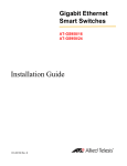
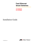
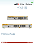
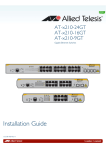
AT-6101GP Power over Ethernet Injector AT-6101GP PoE Injector Installation Guide 613-001673 Rev B Copyright © 2012 Allied Telesis, Inc. All rights reserved. No part of this publication may be reproduced without prior written permission from Allied Telesis, Inc. Allied Telesis and the Allied Telesis logo are trademarks of Allied Telesis, Incorporated. All other product names, company names, logos or other designations mentioned herein are trademarks or registered trademarks of their respective owners. Allied Telesis, Inc. reserves the right to make changes in specifications and other information contained in this document without prior written notice. The information provided herein is subject to change without notice. In no event shall Allied Telesis, Inc. be liable for any incidental, special, indirect, or consequential damages whatsoever, including but not limited to lost profits, arising out of or related to this manual or the information contained herein, even if Allied Telesis, Inc. has been advised of, known, or should have known, the possibility of such damages. Electrical Safety and Emissions Standards This product meets the following standards. U.S. Federal Communications Commission Declaration of Conformity Manufacturer Name: Allied Telesis, Inc. Declares that the product: PoE Ethernet Injector Model Numbers: AT-6101GP This product complies with FCC Part 15B, Class B Limits: This device complies with part 15 of the FCC Rules. Operation is subject to the following two conditions: (1) This device must not cause harmful interference, and (2) this device must accept any interference received, including interference that may cause undesired operation. Radiated Energy Note: This equipment has been tested and found to comply with the limits for a Class B digital device pursuant to Part 15 of FCC Rules. These limits are designed to provide reasonable protection against harmful interference in a residential installation. This equipment generates, uses and can radiate radio frequency energy and, if not installed and used in accordance with instructions, may cause harmful interference to radio or television reception, which can be determined by turning the equipment off and on. The user is encouraged to try to correct the interference by one or more of the following measures: - Reorient or relocate the receiving antenna. - Increase the separation between the equipment and the receiver. - Connect the equipment into an outlet on a circuit different from that to which the receiver is connected. - Consult the dealer or an experienced radio/TV technician for help. Changes and modifications not expressly approved by the manufacturer or registrant of this equipment can void your authority to operate this equipment under Federal Communications Commission rules. Industry Canada This Class B digital apparatus meets all requirements of the Canadian Interference-Causing Equipment Regulations. Cet appareil numérique de la classe B respecte toutes les exigences du Règlement sur le matériel brouilleur du Canada. RFI Emissions FCC Class B, CISPR 22 Class B, EN55022 Class B, VCCI Class B, C-TICK Immunity EN55024 Electrical Safety UL 60950-1 (CULUS), EN60950 (TUV), CE 3 Chapter : Translated Safety Statements Important: The indicates that a translation of the safety statement is available in a PDF document titled “Translated Safety Statements” posted on the Allied Telesis website at www.alliedtelesis.com. 4 Table of Contents Preface .............................................................................................................................................................. 7 Document Conventions................................................................................................................................ 8 Allied Telesis Contact Information................................................................................................................ 9 Chapter 1: Overview ..................................................................................................................................... 11 Features ..................................................................................................................................................... 12 AT-6101GP PoE Injector ..................................................................................................................... 12 10/100/1000 Mbps Twisted Pair Ports................................................................................................. 12 LEDs.................................................................................................................................................... 12 Installation Options .............................................................................................................................. 12 Wiring Configuration ............................................................................................................................ 12 Maximum Distance .............................................................................................................................. 12 Cable Requirements............................................................................................................................ 13 Port Pinouts ......................................................................................................................................... 13 Hardware Description................................................................................................................................. 14 LEDs .......................................................................................................................................................... 15 Chapter 2: Installation .................................................................................................................................. 17 Reviewing Safety Precautions ................................................................................................................... 18 Choosing a Site for the AT-6101GP PoE Injector ...................................................................................... 20 Unpacking the AT-6101GP PoE Injector.................................................................................................... 21 Installation Procedures............................................................................................................................... 22 Table Top Installation .......................................................................................................................... 22 Wall Installation ................................................................................................................................... 22 Ethernet Cable Installation .................................................................................................................. 23 AC Power Cord Installation ................................................................................................................. 24 Chapter 3: Troubleshooting ........................................................................................................................ 25 Technical Specifications ............................................................................................................................... 27 Physical Specifications............................................................................................................................... 27 Environmental Specifications ..................................................................................................................... 27 Power Specifications.................................................................................................................................. 27 Certifications .............................................................................................................................................. 28 RJ-45 Twisted Pair Port Pinouts ................................................................................................................ 28 1 Contents 2 List of Figures Figure 1. AT-6101GP PoE Injector ......................................................................................................................................14 Figure 2. AC Power Input Connector...................................................................................................................................14 Figure 3. AT-6101GP LEDs.................................................................................................................................................15 Figure 4. AT-6101GP PoE Injector Items ............................................................................................................................21 Figure 5. Marking the Screw Hole Locations .......................................................................................................................22 Figure 6. Securing the AT-6101GP PoE Injector to the Wall...............................................................................................23 Figure 7. Connecting Ethernet Cables.................................................................................................................................23 Figure 8. Connecting AC Power Cord for Table Top Installation.........................................................................................24 Figure 9. Connecting AC Power Cord for Wall Installation ..................................................................................................24 Figure 10. RJ-45 Socket Pin Layout (Front View) ...............................................................................................................28 3 Figures 4 List of Tables Table 1. Table 2. Table 3. Table 4. Table 5. Table 6. Table 7. Table 8. Twisted Pair Cable for the 10/100/1000Base-T Ports ..........................................................................................13 10/100Base-TX Port LEDs ..................................................................................................................................15 Physical Specifications .........................................................................................................................................27 Environmental Specifications ................................................................................................................................27 Power Specifications ............................................................................................................................................27 Certifications .........................................................................................................................................................28 Pin Signals for 10 and 100 Mbps ..........................................................................................................................28 Pin Signals for 1000 Mbps ....................................................................................................................................29 5 Tables 6 Preface This guide contains the installation instructions for the AT-6101 PoE Injector Installation Guide. This preface contains the following sections: ❒ “Document Conventions” on page 8 ❒ “Allied Telesis Contact Information” on page 9 7 Preface Document Conventions This document uses the following conventions: Note Notes provide additional information. Caution Cautions inform you that performing or omitting a specific action may result in equipment damage or loss of data. Warning Warnings inform you that performing or omitting a specific action may result in bodily injury. 8 AT-6101 PoE Injector Installation Guide Allied Telesis Contact Information If you need assistance with this product, you may contact Allied Telesis technical support by going to the Support & Services section of the Allied Telesis web site at www.alliedtelesis.com/support. You can find links for the following services on this page: ❒ 24/7 Online Support - Enter our interactive support center to search for answers to your questions in our knowledge database, check support tickets, learn about RMAs, and contact Allied Telesis technical experts. ❒ USA and EMEA phone support - Select the phone number that best fits your location and customer type. ❒ Hardware warranty information - Learn about Allied Telesis warranties and register your product online. ❒ Replacement Services - Submit a Return Merchandise Authorization (RMA) request via our interactive support center. ❒ Documentation - View the most recent installation guides, user guides, software release notes, white papers and data sheets for your product. ❒ Software Updates - Download the latest software releases for your product. For sales or corporate contact information, go to www.alliedtelesis.com/purchase and select your region. 9 Preface 10 Chapter 1 Overview This chapter contains the following sections: “Features” on page 12 “Hardware Description” on page 14 “LEDs” on page 15 11 Chapter 1: Overview Features Here are the features of this product: AT-6101GP PoE Injector 10/100/1000 Mbps Twisted Pair Ports LEDs Installation Options Wiring Configuration Maximum Distance 12 The major features of the AT-6101GP PoE Injector are: Power over Ethernet Injector for 10/100/1000BaseT Remote power feeding Overload and short circuit protection Mixes Ethernet and power into RJ-45 port Delivers power up to 100 meters Light weight and compact size Plug-and-Play 10/100/1000 Mbps Twisted Pair Ports Power over Ethernet output power of 55V @ 0.6A IEEE802.3at compliant The AT-6101GP PoE Injector features two ports that are: 10Base-T, 100Base-TX, and 1000Base-T compliant RJ-45 connectors The AT-6101GP PoE Injector has the following LEDs: AC Power Feeding Power The AT-6101GP PoE Injector may be installed in the following ways: Desk or tabletop Wall mounting The wiring configuration between the ports on the AT-6101GP are a straight-through connections. Each port has a maximum operating distance of 100 meters (328 feet). AT-6101 PoE Injector Installation Guide Cable Requirements Port Pinouts The cable requirements of the ports are given in Table 1. Table 1. Twisted Pair Cable for the 10/100/1000Base-T Ports Cable Type 10Mbps 100Mbps 1000Mbps Standard TIA/EIA 568-Bcompliant Category 3 shielded or unshielded cabling with 100 ohm impedance and a frequency of 16 MHz. Yes Yes No Standard TIA/EIA 568-Acompliant Category 5 or TIA/ EIA 568-B-compliant Enhanced Category 5 (Cat 5e) shielded or unshielded cabling with 100 ohm impedance and a frequency of 100 MHz. Yes Yes Yes Standard TIA/EIA 568-Bcompliant Category 6 or 6a shielded cabling. Yes Yes Yes Refer to Table 7 on page 28 for the port pinouts of the 10/100Base-TX/1000Base-T twisted pair ports. 13 Chapter 1: Overview Hardware Description The AT-6101GP PoE Injector is shown in Figure 1. Figure 1. AT-6101GP PoE Injector DATA IN Port: This port, shown in Figure 1, in is an RJ-45 Ethernet connector where data is received and transmitted through the AT-6101GP PoE Injector. DATA OUT Port: This port, shown in Figure 1, is an RJ-45 Ethernet connector where data is received and transmitted through the AT-6101GP PoE Injector and provides PoE power along with the Ethernet data to a PoE device. AC Power Input Connector: This connector, shown in Figure 2, connects the AC power source to the AT-6101GP PoE Injector. Figure 2. AC Power Input Connector 14 AT-6101 PoE Injector Installation Guide LEDs The LEDs of the AT-6101GP PoE Injector are shown in Figure 3 and described in Table 2. Figure 3. AT-6101GP LEDs Table 2. 10/100Base-TX Port LEDs LED State Off AC Power Solid Green Off PoE Power Solid Green Description No AC power is being provided to the unit. AC power is being provided to the unit. The port is not providing PoE power to the DATA OUT port. The port is providing PoE power to the DATA OUT port. 15 Chapter 1: Overview 16 Chapter 2 Installation You may install the AT-6101GP PoE Injector on a table or on a wall. This chapter contains the following installation procedures: “Reviewing Safety Precautions” on page 18 “Choosing a Site for the AT-6101GP PoE Injector” on page 20 “Unpacking the AT-6101GP PoE Injector” on page 21 “Installation Procedures” on page 22 17 Chapter 2: Installation Reviewing Safety Precautions Please review the following safety precautions before you begin to perform the installation procedure. Note The indicates that a translation of the safety statement is available in a PDF document titled Translated Safety Statements. Warning To prevent electric shock, do not remove the cover. No userserviceable parts inside. This unit contains hazardous voltages and should only be opened by a trained and qualified technician. To avoid the possibility of electric shock, disconnect electric power to the product before connecting or disconnecting the LAN cables. E1 Warning Do not work on equipment or cables during periods of lightning activity. E2 Warning Power cord is used as a disconnection device. To de-energize equipment, disconnect the power cord. E3 Warning Class I Equipment. This equipment must be earthed. The power plug must be connected to a properly wired earth ground socket outlet. An improperly wired socket outlet could place hazardous voltages on accessible metal parts. E4 Pluggable Equipment. The socket outlet shall be installed near the equipment and shall be easily accessible. E5 Warning: Operating Temperature. This product is designed for a maximum ambient temperature of 40° degrees C. E7 All Countries: Install product in accordance with local and National Electrical Codes. E8 18 AT-6101 PoE Injector Installation Guide Warning Only trained and qualified personnel are allowed to install or replace this equipment. E14 Circuit Overloading: Consideration should be given to the connection of the equipment to the supply circuit and the effect that overloading of circuits might have on overcurrent protection and supply wiring. Appropriate consideration of equipment nameplate ratings should be used when addressing this concern. E21 Warning To reduce the risk of electric shock, the PoE ports on this product must not connect to cabling that is routed outside the building where this device is located. E40 Caution The unit does not contain serviceable components. Please return damaged units for servicing. E42 19 Chapter 2: Installation Choosing a Site for the AT-6101GP PoE Injector Observe these guidelines when planning the installation of the AT-6101GP 20 If you plan to install the power injector on a table, the table should be level and stable. The power outlet should be located near the power injector and be easily accessible. The site should allow for easy access to the ports on the front of the power injector, so that you can easily connect and disconnect cables, and view the port LEDs. The site should not expose the power injector to moisture or water. The site should be a dust-free environment. The site should include dedicated power circuits or power conditioners to supply reliable electrical power to the network devices. AT-6101 PoE Injector Installation Guide Unpacking the AT-6101GP PoE Injector The AT-6101GP PoE Injector comes with the items listed in Table 4. Verify that the contents of the shipping container matches the items listed. If any item in the shipping container is missing or damaged, contact your Allied Telesis sales representative for assistance. Note Retain the original packaging material in the event you need to return the unit to Allied Telesis 1 AT-6101GP PoE Injector 2 Wall Anchors 2 Wall Screws 1 Regional AC Power Cord Figure 4. AT-6101GP PoE Injector Items 21 Chapter 2: Installation Installation Procedures Depending on where you install the unit. perform the following procedures when installing the AT-6101GP PoE Injector: Table Top Installation ”Table Top Installation” or ”Wall Installation” “Ethernet Cable Installation” on page 23 “AC Power Cord Installation” on page 24 For installation of the AT-6101GP PoE Injector on a table top, perform the following procedure: 1. Position the AT-6101GP PoE Injector on a table top so it that conforms to the guidelines listed in “Choosing a Site for the AT-6101GP PoE Injector” on page 20. 2. Go to “Ethernet Cable Installation” on page 23 for the next step in the installation. Wall Installation Installing the AT-6101GP PoE Injector on a wall requires the following items: Two wall screws (included with the power injector) Two wall anchors (included with the power injector) Perform the following procedure for installation of the AT-6101GP PoE Injector on a wall: 1. Hold the AT-6101GP against the wall where it is to be installed. The power injector should be oriented such that the AC power connector is facing up and the Ethernet connectors are facing down. Use a pencil or pen to mark the wall locations of the mounting screw holes as illustrated in Figure 5. Figure 5. Marking the Screw Hole Locations 22 AT-6101 PoE Injector Installation Guide 2. Install the two wall anchors into the wall at the locations marked in the previous step. The anchors require 0.635 mm (0.25 in.) holes. 3. Hold the power injector on the wall so that the mounting holes align with the anchors previously installed. Secure the unit with the two wall mounting screws as shown in Figure 6. Figure 6. Securing the AT-6101GP PoE Injector to the Wall 4. Go to ”Ethernet Cable Installation” for the next step in the installation. Ethernet Cable Installation 1. Install two Ethernet cables into the AT-6101GP RJ-45 Ethernet ports marked DATA OUT and DATA IN as shown in Figure 7. Figure 7. Connecting Ethernet Cables 2. Connect the DATA OUT port cable to the PoE device. Connect the DATA IN port cable to the other end device in your network. 23 Chapter 2: Installation AC Power Cord Installation Depending on your installation, connect the AC power cord as shown in Figure 8 (table top installation) or Figure 9 (wall installation). Figure 8. Connecting AC Power Cord for Table Top Installation Figure 9. Connecting AC Power Cord for Wall Installation 24 Chapter 3 Troubleshooting This chapter contains suggestions on how to troubleshoot the installation of the AT-6101GP PoE Injector if a problem occurs. Problem: All PoE injector LEDs are off even though the ports are connected to network devices. Solution: Verify that AC power is connected to the AT-6101GP PoE Injector. 25 Chapter 3: Troubleshooting 26 Appendix A Technical Specifications Physical Specifications Table 3. Physical Specifications Dimensions (H x W x D) 36 mm x 65 mm x 140 m Weight 300 grams (0.66 lb) Environmental Specifications Table 4. Environmental Specifications Operating Temperature 0° C to 40° C (32° F to 104° F) Storage Temperature 20° C to 80° C (-29° F to 27° Operating Humidity 10% to 90% noncondensing Storage Humidity 10% to 95% noncondensing Power Specifications Table 5. Power Specifications Power Consumption 36 watts Input Voltage 100-240 VAC, 0.72 A, 50/60 Hz PoE Power Output 55V @ 0.6 A 27 Appendix A: Technical Specifications Certifications Table 6. Certifications EMI (Emissions) FCC Class B, CE EMC (Immunity) EN55024 Electrical Safety EN60950-1 (TUV), UL 60950-1 (CULUS) Quality and Reliability MTBF > 116685 hrs @ 25° C Compliance Marks CE, CULUS, TUV, C-Tick RJ-45 Twisted Pair Port Pinouts Figure 10 illustrates the pin layout of the RJ-45 connectors and ports. Figure 10. RJ-45 Socket Pin Layout (Front View) Table 7 lists the pin signals for 10 and 100 Mbps. Table 7. Pin Signals for 10 and 100 Mbps 28 Pin MDI Signal MDI-X Signal 1 TX+ RX+ 2 TX- RX- 3 RX+ TX+ 4 Not used Not used 5 Not used Not used 6 RX- TX- 7 Not used Not used 8 Not used Not used AT-6101 PoE Injector Installation Guide Table 8 lists the pin signals when a port operating at 1000 Mbps. Table 8. Pin Signals for 1000 Mbps Pinout Pair 1 Pair 1 + 2 Pair 1 - 3 Pair 2 + 4 Pair 3 + 5 Pair 3 - 6 Pair 2 - 7 Pair 4 + 8 Pair 4 - 29 Appendix A: Technical Specifications 30