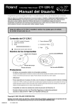
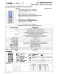
1
Programming
Washer-Extractors
UW Pocket Hardmount
B-Series Microcomputer
2 Speed
Models UW35B2 and UW60B2
NORMAL
WASH
ADD
BLEACH
RINSE
SPIN
DOOR
NOTA: El manual en
español aparece después
del manual en inglés.
PERM PRESS
HOT
HOT
LIGHT SOIL
VISA TM
HOT
WARM
HEAVY SOIL
UNIFORMS
START
HOT
HOT
STAINED
DELICATE
HOT
COLD
DOMESTIC MODELS
95C
95C
60C
60C
40C
40C
30C
<
<
INTERNATIONAL MODELS
PHM1392C
PHM1
www.comlaundry.com
Part No. F232168R2
November 2005
Table of
Contents
Safety Information..............................................................................
Important Safety Instructions ...............................................................
3
3
Programming ......................................................................................
Entering Program Mode .......................................................................
Determining Firmware ID Code...........................................................
Setup Mode (For Models With Firmware ID Code
“o2HC”, “o2UC”, “ouHC” and “ouUC”) ......................................
Cycle and Error Count ..........................................................................
Setup Mode (For Earlier Models) ....................................................
Cycle and Error Count ..........................................................................
Programming Cycle Segments.........................................................
Options for Each Segment ....................................................................
To Edit an Entire Wash Cycle Formula................................................
Wash 1 – Wash 4 .............................................................................
Rinse 1 – Rinse 4 .............................................................................
Abnormal Conditions............................................................................
Door Open During Operation ..........................................................
Excessive Fill Time..........................................................................
Door Will Not Open.........................................................................
Excessive Drain Time ......................................................................
Drain Error (For Models With Firmware ID Code
“o2HC”, “o2UC”, “ouHC” and “ouUC”) ......................................
Temperature Probe Sensor Problem ................................................
Frame Limit Switch Trip .................................................................
Rapid Advance (For Models With Firmware ID Code
“o2HC”, “o2UC”, “ouHC” and “ouUC”) ......................................
How to Rapid Advance During All Steps (Except First Fill Step) ..
How to Rapid Advance (During First Fill Step) ..............................
Test Cycle .............................................................................................
Permanent Diagnostic Test Cycle.........................................................
Cycle Charts for Domestic OPL Models Built After April 2005
(Displays P-F5) ..................................................................................
Cycle Charts for Domestic OPL Models Built Prior to April 2005
(Displays P-F1) ..................................................................................
Cycle Charts for International OPL......................................................
5
5
5
6
6
7
7
8
9
13
13
14
16
16
16
16
16
16
16
16
17
17
17
17
18
20
23
26
© Copyright 2005, Alliance Laundry Systems LLC
All rights reserved. No part of the contents of this book may be reproduced or transmitted in any form or by any
means without the expressed written consent of the publisher.
F232168
© Copyright, Alliance Laundry Systems LLC – DO NOT COPY or TRANSMIT
1
Notes
2
© Copyright, Alliance Laundry Systems LLC – DO NOT COPY or TRANSMIT
F232168
Safety Information
Precautionary statements (“DANGER,” “WARNING,”
and “CAUTION”), followed by specific instructions,
are found in this manual and on machine decals. These
precautions are intended for the personal safety of the
operator, user, servicer, and those maintaining the
machine.
DANGER
Important Safety Instructions
WARNING
To reduce the risk of fire, electric shock,
serious injury or death to persons when
using your washer, follow these basic
precautions:
W023
DANGER indicates the presence of a
hazard that will cause severe personal
injury, death, or substantial property
damage if the danger is ignored.
WARNING
WARNING indicates the presence of a
hazard that can cause severe personal
injury, death, or substantial property
damage if the warning is ignored.
CAUTION
CAUTION indicates the presence of a
hazard that will or can cause minor
personal injury or property damage if the
caution is ignored.
Additional precautionary statements (“IMPORTANT”
and “NOTE”) are followed by specific instructions.
IMPORTANT: The word “IMPORTANT” is used
to inform the reader of specific procedures where
minor machine damage will occur if the procedure
is not followed.
IMPORTANT: The word “NOTE” is used to
communicate installation, operation, maintenance
or servicing information that is important but not
hazard related.
1. Read all instructions before using the washer.
2. Refer to the grounding instructions in the
installation manual for the proper grounding of
the washer.
3. Do not wash textiles that have been previously
cleaned in, washed in, soaked in, or spotted with
gasoline, kerosene, waxes, cooking oils,
dry-cleaning solvents, or other flammable or
explosive substances as they give off vapors that
could ignite or explode.
4. Do not add gasoline, dry-cleaning solvents, or
other flammable or explosive substances to the
wash water. These substances give off vapors that
could ignite or explode.
5. Under certain conditions, hydrogen gas may be
produced in a hot water system that has not been
used for two weeks or more. HYDROGEN GAS
IS EXPLOSIVE. If the hot water system has not
been used for such a period, before using a
washing machine or combination washer-dryer,
turn on all hot water faucets and let the water
flow from each for several minutes. This will
release any accumulated hydrogen gas. The gas is
flammable; do not smoke or use an open flame
during this time.
6. Do not allow children to play on or in the washer.
Close supervision of children is necessary when
the washer is used near children. This is a safety
rule for all appliances.
7. Before the washer is removed from service or
discarded, remove the door to the washing
compartment.
8. Do not reach into the washer if the wash drum is
moving.
F232168
© Copyright, Alliance Laundry Systems LLC – DO NOT COPY or TRANSMIT
3
Safety Information
9. Do not install or store the washer where it will be
exposed to water and/or weather.
10. Do not tamper with the controls.
11. Do not repair or replace any part of the washer, or
attempt any servicing unless specifically
recommended in the user-maintenance
instructions or in published user-repair
instructions that the user understands and has the
skills to carry out.
12. To reduce the risk of an electric shock or fire, DO
NOT use an extension cord or an adapter to
connect the washer to the electrical power source.
13. Use washer only for its intended purpose,
washing textiles.
14. ALWAYS disconnect the washer from electrical
supply before attempting any service. Disconnect
the power cord by grasping the plug, not the cord.
15. Install the washer according to the installation
instructions. All connections for water, drain,
electrical power and grounding must comply
with local codes and be made by licensed
personnel when required.
16. To reduce the risk of fire, textiles which have
traces of any flammable substances such as
vegetable oil, cooking oil, machine oil,
flammable chemicals, thinner, etc. or anything
containing wax or chemicals such as in mops and
cleaning cloths, must not be put into the washer.
These flammable substances may cause the
fabric to catch on fire by itself.
17. Do not use fabric softeners or products to
eliminate static unless recommended by the
manufacturer of the fabric softener or product.
18. Keep washer in good condition. Bumping or
dropping the washer can damage safety features.
If this occurs, have washer checked by a qualified
service person.
4
19. Replace worn power cords and/or loose plugs.
20. Be sure water connections have a shut-off valve
and that fill hose connections are tight. CLOSE
the shut-off valves at the end of each wash day.
21. Loading door MUST BE CLOSED any time the
washer is to fill, tumble or spin. DO NOT
bypass the loading door switch by permitting the
washer to operate with the loading door open.
22. Always read and follow manufacturer’s
instructions on packages of laundry and cleaning
aids. Heed all warnings or precautions. To reduce
the risk of poisoning or chemical burns, keep
them out of the reach of children at all times
(preferably in a locked cabinet).
23. Always follow the fabric care instructions
supplied by the textile manufacturer.
24. Never operate the washer with any guards and/or
panels removed.
25. DO NOT operate the washer with missing or
broken parts.
26. DO NOT bypass any safety devices.
27. Failure to install, maintain, and/or operate this
washer according to the manufacturer’s
instructions may result in conditions which can
produce bodily injury and/or property damage.
NOTE: The WARNINGS and IMPORTANT
SAFETY INSTRUCTIONS appearing in this
manual are not meant to cover all possible
conditions and situations that may occur. Common
sense, caution and care must be exercised when
installing, maintaining, or operating the washer.
Any problems or conditions not understood should be
reported to the dealer, distributor, service agent or the
manufacturer.
© Copyright, Alliance Laundry Systems LLC – DO NOT COPY or TRANSMIT
F232168
Programming
NOTE: The machines are factory-programmed
with basic cycles to make the units operational
without programming at the installation.
Entering Program Mode
1. Open control compartment lid.
2. Locate Program/Run switch on the computer
board. (This is accessed through a cutout in the
metal control unit cover.) This switch protrudes
from the rear of the electronic control unit cover.
3. Flip switch to the left (as seen from the front of
machine) to enter Program Mode.
4. Display will show a temperature.
Determining Firmware ID Code
1. Turn on the main power source (circuit breaker or
cut-off switch on wall).
2. Display will show Firmware ID code (i.e.,
“o2UC” and “ouUC” etc...).
3. Record Firmware ID Code for future reference.
F232168
© Copyright, Alliance Laundry Systems LLC – DO NOT COPY or TRANSMIT
5
Programming
Setup Mode (For Models With Firmware ID
Code “o2HC”, “o2UC”, “ouHC” and
“ouUC”)
NOTE: In Setup Mode, certain machine functions
can be configured. The settings in this mode are
related to how the machine is equipped from the
factory. Usually, these would not be changed in this
field.
NOTE: Enter Setup Mode through the Program Mode.
1. Press (*) key. Display will show “FAr” or “CEL”.
NOTE: This selects whether temperatures display
in degrees Fahrenheit (F) or Celsius (C), if control
is equipped with a temperature sensor. Press the
(∧) or (∨) key to change.
NOTE: Changing degrees “FAr” or “CEL” only
has an effect if the control has a temperature probe
connected and/or heat capability.
2. Press START key.
3. Model will display “HEAt” or “noHt”. Change
the selection by pressing the (∧) or (∨) key.
4. Press START key to continue to the next step.
NOTE: If set for “HEAt”, the control has heat
capability enabled. The washer-extractor MUST
have electric or steam heat, and a temperature
probe. If display shows “noHt”, or if the message
“HEAt” or “noHt” does NOT display, the control
does NOT have heat capability.
5. Certain models will display “EFIL” or “ESUP”.
For these models, the control provides a spare
output (for certain models). The spare output can
be set up to control an extra fill valve (“EFIL”),
with the ability to fill to a programmable water
level (just as for regular fills), OR the spare
output can be set up to control an extra chemical
supply signal (“ESUP”).
6. Press START keypad.
7. Certain models display “bEEP” (control sounds
beeper during Add Bleach [Supply 2]) or “nobP”
(control does NOT sound beeper during Add
Bleach [Supply 2]). Change selection by pressing
(∧) or (∨) keypad.
8. Press START keypad.
NOTE: If “EFIL” or “ESUP” does NOT display,
the extra fill capability is NOT present. If either
message does display, change the selection by
pressing the (∧) or (∨) key. Press START key to
6
return to Program Mode. Refer to “Programming
Cycle Segments” section for additional information.
9. “Adv” or “noAd” will display. If “Adv” is set,
control will advance to the next step when up
arrow keypad is pressed during a regular cycle. If
“noAd” is set, control cannot advance during a
regular cycle, but can advance during the factory
test cycle when up arrow keypad is pressed.
10. Press START (enter) keypad to continue to next
step.
11. “PtIM” or “EtIM” will display. “PtIM” means
control will not display remaining time in a cycle.
“EtIM” means control will display an estimated
remaining time for a fill and drain. Press the up
or down keypad to change “PtIM”/ “EtIM”
selection.
12. Press START (enter) keypad to continue to the
next step.
Cycle and Error Count
1. To read, enter Program Mode. Refer to Entering
Program Mode.
2. Press START (enter) keypad. Display shows
“Erdn” (indicates Drain Error count).
3. Press START (enter) keypad. Display shows a
number (2 or 3 digits) showing how many drain
errors have occurred. This number can range
from ‘00’ to ‘255’, and cannot be set to zero.
4. Press START (enter) keypad. Display shows
“ErFL” (indicates Fill Error count).
5. Press START (enter) keypad. Display shows a
number (2 or 3 digits showing how many fill
errors have occurred. This number can range
from ‘00’ to 255’, and cannot be set to zero.
6. Press START (enter) keypad. Display shows
“CYC “ (indicates Cycle count).
7. Press START (enter) keypad. Displays show a
number (up to 4 digits) showing how many
complete cycles have been operated. This
excludes cycles stopped because of an error.
8. Press START (enter) keypad.
9. If display does not show “E Pr”, control will
revert to normal program mode.
10. If display shows “E Pr”, this is for factory
reference regarding power interruption. Press
START (enter) keypad. A number will display.
Press START (enter) keypad. After a brief pause,
the control will display normal program mode.
© Copyright, Alliance Laundry Systems LLC – DO NOT COPY or TRANSMIT
F232168
Programming
Setup Mode (For Earlier Models)
NOTE: In Setup Mode, certain machine functions
can be configured. The settings in this mode are
related to how the machine is equipped from the
factory. Usually, these would not be changed in this
field.
NOTE: Enter Setup Mode through the Program
Mode.
1. Press (*) key. Display will show “FAr” or “CEL”.
NOTE: This selects whether temperatures display
in degrees Fahrenheit (F) or Celsius (C), if control
is equipped with a temperature sensor. Press the
(∧) or (∨) key to change.
NOTE: Changing degrees “FAr” or “CEL” only
has an effect if the control has a temperature probe
connected and/or heat capability.
2. Press START key.
3. Model will display “HEAt” or “noHt”. Change
the selection by pressing the (∧) or (∨) key.
NOTE: If “EFIL” or “ESUP” does NOT display,
the extra fill capability is NOT present. If either
message does display, change the selection by
pressing the (∧) or (∨) key. Press START key to
return to Program Mode. Refer to “Programming
Cycle Segments” section for additional information.
Cycle and Error Count
The control logs cycle count (total of all cycles
completed).
●
To read, enter Program Mode.
●
Press START (enter) key. Display will show the
cycle count.
●
Press START (enter) key. Display will show
certain error conditions that may have been
recorded by the control.
●
Read the information when consulting technical
assistance as needed.
●
Step through the error log by pressing START
key repeatedly until display reverts to normal
Program Mode (showing a temperature).
4. Press START key to continue to the next step.
NOTE: If set for “HEAt”, the control has heat
capability enabled. The washer-extractor MUST
have electric or steam heat, and a temperature
probe. If display shows “noHt”, or if the message
“HEAt” or “noHt” does NOT display, the control
does NOT have heat capability.
5. Certain models will display “EFIL” or “ESUP”.
For these models, the control provides a spare
output (for certain models). The spare output can
be set up to control an extra fill valve (“EFIL”),
with the ability to fill to a programmable water
level (just as for regular fills), OR the spare
output can be set up to control an extra chemical
supply signal (“ESUP”).
6. Press START keypad.
7. Certain models display “bEEP” (control sounds
beeper during Add Bleach [Supply 2]) or “nobP”
(control does NOT sound beeper during Add
Bleach [Supply 2]). Change selection by pressing
(∧) or (∨) keypad.
8. Press START keypad.
F232168
© Copyright, Alliance Laundry Systems LLC – DO NOT COPY or TRANSMIT
7
Programming
Programming Cycle Segments
After entering Program Mode, display will show a
temperature. Press the (∧) key to enter Cycle
Programming Mode. The display will reference cycles
by number. Cycle 1 will show first. Use the (∧) or (∨)
key to select cycle to be edited. Press START key to
move into the following menu of options (starting at
Table 1).
The machine is preprogrammed with eight wash cycle
formulas that can be edited.
To edit any of these cycles, enter Program Mode. In
Program Mode, cycles are selected by number
(1 through 8) as opposed to the Run Mode, where
cycles are selected by pressing one of the eight
corresponding keys. The keys must serve different
functions in each mode because there are more
functions than keys in Program Mode.
NOTE: While cycle is running, pressing the START
keypad shows the temperature. Pressing the
START keypad again returns display to time
remaining or displays temperature for several
seconds, depending on version software.
In Run Mode the top left key selects Cycle 1, the key
directly below it selects Cycle 2, etc. Figure 1 shows
which key selects each cycle in Run Mode.
16 17 18 19
16 17 18 19
1
2
2
1
5
5
15
NORMAL
PERM PRESS
HOT
HOT
WASH
14
ADD
BLEACH
13
LIGHT SOIL
VISA TM
HOT
WARM
HEAVY SOIL
UNIFORMS
HOT
HOT
STAINED
DELICATE
HOT
COLD
RINSE
SPIN
12
START
DOOR
11
15
6
95C
95C
60C
60C
40C
40C
6
14
7
13
8
12
7
8
11
30C
3
9
4
DOMESTIC MODELS
3
4
<
9
10
<
10
PHM538R
INTERNATIONAL MODELS
PHM538R
1
2
3
4
5
6
7
8
9
10
Cycle 1
Cycle 2
Cycle 3
Cycle 4/Up Edit
Cycle 5
Cycle 6
Cycle 7
Cycle 8/Down Edit
START Keypad
CLEAN FILTER Indicator LED
(Active only for C80 models)
11
12
13
14
15
16
17
18
19
Door Open LED
Spin Cycle LED
Rinse Cycle LED
Add Bleach LED
Wash Cycle LED
Out-of-Balance Indicator Dot
(Variable-speed only)
High Water Level Indicator Dot
Medium Water Level Indicator Dot
Low Water Level Indicator Dot
Figure 1
8
© Copyright, Alliance Laundry Systems LLC – DO NOT COPY or TRANSMIT
F232168
Programming
Options for Each Segment
Cycle Steps Available
(NOTE: WASH, ADD BLEACH, RINSE, and SPIN
LEDs light ONLY when a cycle formula is in
operation.)
Setting Options for Cycle Steps
(Press START key to advance to next row selection,
(∧) to increase a value or change, (∨) to decrease a
value or change, or (∗) to save and exit.)
Normal† or Gentle†† agitation
Agitation in effect for cycle
Wash 1 (displayed as “USH1”), lights WASH LED (during operation)
Time for agitation (excludes fill, drain, spin, heat)
0 or 2-30 minutes (one-minute increments)
Fill valves (temperature)
Cold, Hot, Warm (Cold & Hot) or “EFIL”†††
Fill water level control
Low, Medium, or High
Supply
None (0), 1, 2 (liquid bleach††††), 3, 4, 5†††††, 6 (1 and 2
together displays as “SUP6”), or 7††††† (Supply 4 and extra
supply 5 together displays as “SUP7”).
Heat (appears ONLY for models with heat capability)
00F (no heat for segment), or 80°F to 205°F
00C (no heat for segment), or 27°C to 95°C
Drain (Select Drain or No Drain. Final segment drains in
stop routine if No Drain is programmed.)
Drain or No Drain (if No Drain, skips the spin step which
automatically sets that spin time = 0)
Spin time
0 or 30-240 seconds (one-second increments)
Wash 2 (displayed as “USH2”), lights WASH LED (during operation)
Time for agitation (excludes fill, drain, spin, heat)
0 or 2-20 minutes (one-minute increments)
Fill valves (temperature)
Cold, Hot, Warm (Cold & Hot) or “EFIL”†††
Fill water level
Low, Medium, or High
Supply
None (0), 1, 2 (liquid bleach††††), 3, 4, 5†††††, 6 (1 and 2
together displays as “SUP6”), or 7††††† (Supply 4 and extra
supply 5 together displays as “SUP7”).
Heat (appears ONLY for models with heat capability)
00F (no heat for segment), or 80°F to 205°F
00C (no heat for segment), or 27°C to 95°C
Drain (Select Drain or No Drain. Final segment drains in
stop routine if No Drain is programmed.)
Drain or No Drain (if No Drain, skips the spin step which
automatically sets that spin time = 0)
Spin time
0 or 30-240 seconds (one-second increments)
Table 1 (Continued)
†
††
†††
Normal Agitation is 12 seconds forward, 3 seconds
off, 12 seconds reverse, 3 seconds off, and repeat.
Gentle Agitation is 3 seconds forward, 12 seconds
off, 3 seconds reverse, 12 seconds off, and repeat.
Extra Fill (“EFIL”) possible only if configured for
“EFIL” in Setup Mode.
F232168
††††
ADD BLEACH LED lights if Supply 2 is the only
supply programmed and if set up for “bEEP” (refer
to Setup Mode section). ADD BLEACH LED and
Supply 2 signal are on for up to 45 seconds, or until
the programmed water level is reached, whichever
occurs first. If “bEEP” is enabled, beeper begins
beeping when Supply 2 comes on and beeps for 8
seconds.
††††† Appears only if “ESUP” (extra supply) configured
in Setup Mode.
© Copyright, Alliance Laundry Systems LLC – DO NOT COPY or TRANSMIT
9
Programming
Table 1 (Continued)
Cycle Steps Available
(NOTE: WASH, ADD BLEACH, RINSE, and SPIN
LEDs light ONLY when a cycle formula is in
operation.)
Setting Options for Cycle Steps
(Press START key to advance to next row selection,
(∧) to increase a value or change, (∨) to decrease a
value or change, or (∗) to save and exit.)
Wash 3 (displayed as “USH3”), lights WASH LED (during operation)
Time for agitation (excludes fill, heat, drain, spin, heat)
0 or 2-15 minutes (one-minute increments)
Fill valves (temperature)
Cold, Hot, Warm (Cold & Hot) or “EFIL”†††
Fill water level
Low, Medium, or High
Supply
None (0), 1, 2 (liquid bleach††††), 3, 4, 5†††††, 6 (1 and 2
together displays as “SUP6”), or 7††††† (Supply 4 and extra
supply 5 together displays as “SUP7”).
Heat (appears ONLY for models with heat capability)
00F (no heat for segment), or 80°F to 205°F
00C (no heat for segment), or 27°C to 95°C
Drain (Select Drain or No Drain. Final segment drains in
stop routine if No Drain is programmed.)
Drain or No Drain (if No Drain, skips the spin step which
automatically sets that spin time = 0)
Spin time
0 or 30-240 seconds (one-second increments)
Wash 4 (displayed as “USH4”), lights WASH LED (during operation)
Time for agitation (excludes fill, heat, drain, spin, heat)
0 or 2-15 minutes (one-minute increments)
Fill valves (temperature)
Cold, Hot, Warm (Cold & Hot) or “EFIL”†††
Fill water level
Low, Medium, or High
Supply
None (0), 1, 2 (liquid bleach††††), 3, 4, 5†††††, 6 (1 and 2
together displays as “SUP6”), or 7††††† (Supply 4 and extra
supply 5 together displays as “SUP7”).
Heat (appears ONLY for models with heat capability)
00F (no heat for segment), or 80°F to 205°F
00C (no heat for segment), or 27°C to 95°C
Drain (Select Drain or No Drain. Final segment drains in
stop routine if No Drain is programmed.)
Drain or No Drain (if No Drain, skips the spin step which
automatically sets that spin time = 0)
Spin time
0 or 30-240 seconds (one-second increments)
†
††
†††
10
Table 1 (Continued)
Normal Agitation is 12 seconds forward, 3 seconds
†††† ADD BLEACH LED lights if Supply 2 is the only
off, 12 seconds reverse, 3 seconds off, and repeat.
supply programmed and if set up for “bEEP” (refer
to Setup Mode section). ADD BLEACH LED and
Gentle Agitation is 3 seconds forward, 12 seconds
Supply 2 signal are on for up to 45 seconds, or until
off, 3 seconds reverse, 12 seconds off, and repeat.
the programmed water level is reached, whichever
Extra Fill (“EFIL”) possible only if configured for
occurs first. If “bEEP” is enabled, beeper begins
“EFIL” in Setup Mode.
beeping when Supply 2 comes on and beeps for 8
seconds.
††††† Appears only if “ESUP” (extra supply) configured
in Setup Mode.
© Copyright, Alliance Laundry Systems LLC – DO NOT COPY or TRANSMIT
F232168
Programming
Table 1 (Continued)
Cycle Steps Available
(NOTE: WASH, ADD BLEACH, RINSE, and SPIN
LEDs light ONLY when a cycle formula is in
operation.)
Setting Options for Cycle Steps
(Press START key to advance to next row selection,
(∧) to increase a value or change, (∨) to decrease a
value or change, or (∗) to save and exit.)
Rinse 1 (displayed as “rIn1”), lights RINSE LED (during operation)
Time for agitation (excludes fill, drain, spin, heat)
0 or 2-15 minutes (one-minute increments)
Fill valves (temperature)
Cold, Hot, Warm (Cold & Hot) or “EFIL”†††
Fill water level
Low, Medium, or High
Supply
None (0), 1, 2 (liquid bleach††††), 3, 4, 5†††††, 6 (1 and 2
together displays as “SUP6”), or 7††††† (Supply 4 and extra
supply 5 together displays as “SUP7”).
Heat (appears ONLY for models with heat capability)
00F (no heat for segment), or 80°F to 205°F
00C (no heat for segment), or 27°C to 95°C
Drain (Select Drain or No Drain. Final segment drains in
stop routine if No Drain is programmed.)
Drain or No Drain (if No Drain, skips the spin step which
automatically sets that spin time = 0)
Spin time
0 or 30-240 seconds (one-second increments)
Rinse 2 (displayed as “rIn2”), lights RINSE LED (during operation)
Time for agitation (excludes fill, drain, spin, heat)
0 or 2-15 minutes (one-minute increments)
Fill valves (temperature)
Cold, Hot, Warm (Cold & Hot) or “EFIL”†††
Fill water level
Low, Medium, or High
Supply
None (0), 1, 2 (liquid bleach††††), 3, 4, 5†††††, 6 (1 and 2
together displays as “SUP6”), or 7††††† (Supply 4 and extra
supply 5††††† together displays as “SUP7”).
Heat (appears ONLY for models with heat capability)
00F (no heat for segment), or 80°F to 205°F
00C (no heat for segment), or 27°C to 95°C
Drain (Select Drain or No Drain. Final segment drains in
stop routine if No Drain is programmed.)
Drain or No Drain (if No Drain, skips the spin step which
automatically sets that spin time = 0)
Spin time
0 or 30-240 seconds (one-second increments)
†
††
†††
Table 1 (Continued)
Normal Agitation is 12 seconds forward, 3 seconds
†††† ADD BLEACH LED lights if Supply 2 is the only
off, 12 seconds reverse, 3 seconds off, and repeat.
supply programmed and if set up for “bEEP” (refer
to Setup Mode section). ADD BLEACH LED and
Gentle Agitation is 3 seconds forward, 12 seconds
Supply 2 signal are on for up to 45 seconds, or until
off, 3 seconds reverse, 12 seconds off, and repeat.
the programmed water level is reached, whichever
Extra Fill (“EFIL”) possible only if configured for
occurs first. If “bEEP” is enabled, beeper begins
“EFIL” in Setup Mode.
beeping when Supply 2 comes on and beeps for 8
seconds.
††††† Appears only if “ESUP” (extra supply) configured
in Setup Mode.
F232168
© Copyright, Alliance Laundry Systems LLC – DO NOT COPY or TRANSMIT
11
Programming
Table 1 (Continued)
Cycle Steps Available
(NOTE: WASH, ADD BLEACH, RINSE, and SPIN
LEDs light ONLY when a cycle formula is in
operation.)
Setting Options for Cycle Steps
(Press START key to advance to next row selection,
(∧) to increase a value or change, (∨) to decrease a
value or change, or (∗)to save and exit.)
Rinse 3 (displayed as “rIn3”), lights RINSE LED (during operation)
Time for agitation (excludes fill, drain, spin, heat)
0 or 2-15 minutes (one-minute increments)
Fill valves (temperature)
Cold, Hot, Warm (Cold & Hot) or “EFIL”†††
Fill water level
Low, Medium, or High
Supply
None (0), 1, 2 (liquid bleach††††), 3, 4, 5†††††, 6 (1 and 2
together displays as “SUP6”), or 7††††† (Supply 4 and extra
supply 5 together displays as “SUP7”).
Heat (appears ONLY for models with heat capability)
00F (no heat for segment), or 80°F to 205°F
00C (no heat for segment), or 27°C to 95°C
Drain (Select Drain or No Drain. Final segment drains in
stop routine if No Drain is programmed.)
Drain or No Drain (if No Drain, skips the spin step which
automatically sets that spin time = 0)
Spin time
0 or 30-240 seconds (one-second increments)
Rinse 4 (displayed as “rIn4”), lights RINSE LED (during operation)
Time for agitation (excludes fill, heat, drain, spin, heat)
0 or 2-15 minutes (one-minute increments)
Fill valves (temperature)
Cold, Hot, Warm (Cold & Hot) or “EFIL”†††
Fill water level
Low, Medium, or High
Supply
None (0), 1, 2 (liquid bleach††††), 3, 4, 5†††††, 6 (1 and 2
together displays as “SUP6”), or 7††††† (Supply 4 and extra
supply 5 together displays as “SUP7”).
Heat (appears ONLY for models with heat capability)
00F (no heat for segment), or 80°F to 205°F
00C (no heat for segment), or 27°C to 95°C
Drain (Select Drain or No Drain. Final segment drains in
stop routine if No Drain is programmed.)
Drain or No Drain (if No Drain, skips the spin step which
automatically sets that spin time = 0)
Spin time
0 or 1-10 minutes (one-minute increments)
†
††
†††
12
Normal Agitation is 12 seconds forward, 3 seconds
off, 12 seconds reverse, 3 seconds off, and repeat.
Gentle Agitation is 3 seconds forward, 12 seconds
off, 3 seconds reverse, 12 seconds off, and repeat.
Extra Fill (“EFIL”) possible only if configured for
“EFIL” in Setup Mode.
††††
ADD BLEACH LED lights if Supply 2 is the only
supply programmed and if set up for “bEEP” (refer
to Setup Mode section). ADD BLEACH LED and
Supply 2 signal are on for up to 45 seconds, or until
the programmed water level is reached, whichever
occurs first. If “bEEP” is enabled, beeper begins
beeping when Supply 2 comes on and beeps for 8
seconds.
††††† Appears only if “ESUP” (extra supply) configured
in Setup Mode.
© Copyright, Alliance Laundry Systems LLC – DO NOT COPY or TRANSMIT
F232168
Programming
To Edit an Entire Wash Cycle
Formula
Enter Program Mode. Press the (∧) key until display
shows “CY01”.
Press the (∧) or (∨) key until cycle to be edited is
displayed; then press START key to select the cycle
desired. Refer to Figure 1, showing which cycle
number corresponds to each key when in Run Mode.
Agitation for the Cycle
With display showing “CY_x” (x = cycle number),
press the START key. Display shows either “norn”
(for normal agitation), or “GEnt” (for gentle agitation).
Press the (∧) or (∨) key to alter the selection, or the
START key to continue. Each cycle can be set up for
Normal agitation (12 seconds forward, 3 seconds
pause, 12 seconds reverse, 3 seconds pause, repeat) or
Gentle agitation (3 seconds forward, 12 seconds pause,
3 seconds reverse, 12 seconds pause, repeat).
Wash 1 – Wash 4
NOTE: Programming a time other than “00” for
Wash 1 will make the WASH indicator LED light
while this step is running, but NOT in Program
Mode.
The main display shows “USH1” indicating you are in
the Wash segment (number will reflect selected Wash
segment 1-4), otherwise wash segments are identical.
Press START key. Display shows agitation time during
the step: “00” (skips segment) or 2-30 minutes. Wash
2 agitation’s time can be 2-20 minutes, 2-15 minutes
for Wash 3 and Wash 4, or “00” to skip Wash 2, Wash
3, or Wash 4. This is the time after the fill and before
the drain and does not include spin time or time to first
reach a programmed temperature (if your machine is
configured for heat). Press the (∧) or (∨) key to alter
the selection, or the START key to continue.
Display shows “CFIL”, “HFIL”, “bFIL” (for cold, hot,
or warm [both]) or “EFIL”. Press the (∧) or (∨) key to
alter the selection, or the START key to continue.
NOTE: Extra Fill (“EFIL”) possible only if
configured for “EFIL” in Setup Mode. If
configured, a third fill valve can be controlled.
Display shows “LO”, “nEd”, or “HI” for low, medium,
or high water level, respectively. Press the (∧) or (∨)
key to alter the selection, or the START key to
continue.
Display shows “SUP0”, “SUP1”, “SUP2”, “SUP3”,
“SUP4”, “SUP5” (extra supply), “SUP6”, or “SUP7”
(supply 4 and extra supply together), indicating no
supply, supply 1, supply 2, supply 3, supply 4, supply
5 (extra supply), supply 6 (supply 1 and 2 together), or
supply 7 (supply 4 and extra supply 5 together). Press
the (∧) or (∨) key to alter the selection, or the START
key to continue.
NOTE: “SUP5” and “SUP7” appear ONLY if
control is configured for “ESUP” (spare output set
up to operate as an EXTRA supply signal for
external chemical) in Setup Mode. If the alternate
function for the spare output is selected (“EFIL”),
the output will function as an additional fill valve
signal with a programmable water level. In this
case, extra supply function would NOT be
available.
NOTE: If programmed for “SUP2”, the ADD
BLEACH indicator LED light turns on and if set
up for “bEEP” (refer to Setup Mode section) the
buzzer sounds for the first 8 seconds that supply 2
is on.
Press the (∧) or (∨) key to alter the selection or START
key to continue.
The washer-extractor has 5 supply compartments,
designated as compartments 1, 2, 3, 4 and 5.
Compartment 1 is farthest to the rear of machine.
Moving toward the front of machine, compartments
are ordered 2, 3, 4 and 5 (at the front of machine).
Supply signals 1 through 5 correspond to
compartments 1 through 5. Supply signals 1, 2, and 3
have dedicated water valves that flush compartments
1, 2 and 3 (along with the signal being available for
external supplies). Supply signal 4 operates a valve
that flushes compartment 4. The supply signal is
available for external supply connection. This valve is
connected so that it also flushes supply compartment 5
when the supply 4 signal is on. For example, if supply
4 signal is programmed, it will flush compartments 4
and 5. Supply 5 is available to operate an external
supply.
NOTE: For additional assistance, refer to
installation instructions.
F232168
© Copyright, Alliance Laundry Systems LLC – DO NOT COPY or TRANSMIT
13
Programming
Heated Models Only
Rinse 1 – Rinse 4
Display shows temperature in degrees F or C. Display
will show degrees F if configured for “FAr” in Setup
Mode, or degrees C if configured for “CEL” in Setup
Mode. Range is 80°F to 205°F, or 00F (no heat for
segment), or 27°C to 95°C, or 00C (no heat for
segment).
NOTE: Programming a time other than “00” for
this step will make the RINSE indicator LED light
while this step is running, but not in Program
Mode.
Press the (∧) key to increase, or (∨) key to decrease
temperature in one-degree increments. The control
will energize heat and pause cycle timing for up to
50 minutes until the programmed temperature is first
reached.
NOTE: If temperature not reached after
50 minutes, control resumes cycle.
After cycle resumes, control will attempt to maintain
programmed temperature if it senses water in the
machine.
NOTE: Temperature display applies ONLY if
machine is configured for “HEAt” in Setup Mode.
Machine must be equipped with electric or steam
heat and a temperature sensor. If configured for
“noHt” (no heat capability) in Setup Mode,
temperature display does not appear in the
segment. After temperature setting, control will
skip to “drAI”/“nodr” or Spin Time, depending on
version.
If display shows “drAI”/“nodr” during segment
programming, a drain step option can be selected.
Select “drAI” for a drain step followed by an optional
spin. Select “nodr” for no drain step. The machine will
proceed directly to the next segment if “nodr”. Change
the selection by pressing the (∧) or (∨) key. Press
START to continue.
If “drAI” is selected (or if your model does not provide
the option of selecting “drAI”/“nodr”), the display will
show “SPIn” one second, “tInE” one second, and then
the time for spin: “00” (no spin) or 30-240 seconds.
Change the selection by pressing the (∧) or (∨) key.
Press START to continue. Then enter the next segment
(USH2, USH3, USH4 or after USH4, the “rIN1”
segment). Refer to Rinse 1 – Rinse 4 section.
The main display shows “rIN1” indicating you are in
the Rinse segment (number will represent Rinse cycle
selected 1-4). Press START key. Display shows the
time for agitation during the step: “00” (skips
segment) or 2-15 minutes. This is the time after the fill
and before the drain and does not include spin time.
Press the (∧) or (∨) key to alter the selection, or the
START key to continue.
Display shows “CFIL”, “HFIL”, “bFIL” or “EFIL” for
cold, hot, warm (both) or Extra Fill. Press the
(∧) or (∨) key to alter the selection, or the START key
to continue.
NOTE: Extra Fill (“EFIL”) possible only if
configured for “EFIL” in Setup Mode. If
configured, a third valve can be controlled.
Display shows “LO”, “nEd”, or “HI” for low, medium,
or high water level, respectively. Press the (∧) or (∨)
key to alter the selection, or the START key to
continue.
Display shows “SUP0”, “SUP1”, “SUP2”, “SUP3”,
“SUP4”, “SUP5” (extra supply), “SUP6”, or “SUP7”
(supply 4 and extra supply together), indicating no
supply, supply 1, supply 2, supply 3, supply 4,
supply 5 (extra supply), supply 6 (supply 1 and 2
together), or supply 7 (supply 4 and extra supply 5
together). Press the (∧) or (∨) key to alter the
selection, or the START key to continue.
NOTE: “SUP5” and “SUP7” appear ONLY if
control is configured for “ESUP” (spare output set
up to operate as an EXTRA supply signal for
external chemical) in Setup Mode. If the alternate
function for the spare output is selected (“EFIL”),
the output will function as an additional fill valve
signal with a programmable water level. In this
case, extra supply function would NOT be
available.
NOTE: If programmed for “SUP2”, the ADD
BLEACH indicator LED light turns on and if set
up for “bEEP” (refer to Setup Mode section) the
buzzer sounds for the first 8 seconds that supply 2
is on.
Press the (∧) or (∨) key to alter the selection or START
key to continue.
14
© Copyright, Alliance Laundry Systems LLC – DO NOT COPY or TRANSMIT
F232168
Programming
The washer-extractor has 5 supply compartments,
designated as compartments 1, 2, 3, 4 and 5.
Compartment 1 is farthest to the rear of machine.
Moving toward the front of machine, compartments
are ordered 2, 3, 4 and 5 (at the front of machine).
Supply signals 1 through 5 correspond to
compartments 1 through 5. Supply signals 1, 2, and 3
have dedicated water valves that flush compartments
1, 2 and 3 (along with the signal being available for
external supplies). Supply signal 4 operates a valve
that flushes compartment 4. The supply signal is
available for external supply connection. This valve is
connected so that it also flushes supply compartment 5
when the supply 4 signal is on. For example, if supply
4 signal is programmed, it will flush compartments 4
and 5. Supply 5 is available to operate an external
supply.
NOTE: For additional assistance, refer to
installation instructions.
Heated Models Only
Display shows temperature in degrees F or C. Display
will show degrees F if configured for “FAr” in Setup
Mode, or degrees C if configured for “CEL” in Setup
Mode. Range is 80°F to 205°F, or 00F (no heat for
segment), or 27°C to 95°C, or 00C (no heat for
segment).
Press the (∧) key to increase, or (∨) key to decrease
temperature. Temperature changes in one-degree
increments. The control will energize heat and pause
cycle timing for up to 50 minutes until the
programmed temperature is first reached.
If display shows “drAI”/“nodr” during segment
programming, a drain step option can be selected.
Select “drAI” for a drain step followed by an optional
spin. Select “nodr” for no drain step. The machine will
proceed directly to the next segment if “nodr”. Change
the selection by pressing the (∧) or (∨) key. Press
START to continue.
If “drAI” is selected (or if your model does not provide
the option of selecting “drAI”/“nodr”), the display will
show “SPIn” one second, “tInE” one second, and then
the time for spin: “00” (no spin) for 30-240 seconds IF
you are in Rinse 1, 2, or 3. If you are in Rinse 4, the
time for spin will show 0 or 1-10 minutes. Change the
selection by pressing the (∧) or (∨) key. Press START
to continue. Then enter the next segment (rIN2, rIN3,
rIN4 or exit if rIN4 is complete).
IMPORTANT: The spin time in Rinse 4 is
programmed in minutes (0-10 minutes, in
one-minute increments), while other spins are in
seconds to allow for shorter times (such as
45 seconds). (Rinse 4 segment should usually be
used as the final rinse, even where there may be
fewer than four rinses. Program zero time for
preceding rinses you wish to exclude.)
Display shows a temperature. Exit Program Mode by
moving the Program/Run switch back to the left as
seen from the front of the machine.
NOTE: The SPIN indicator LED will automatically
light during the wash cycle when the last spin
programmed in a cycle is operating (regardless of
which segment).
NOTE: If temperature not reached after
50 minutes, control resumes cycle.
After cycle resumes, control will attempt to maintain
programmed temperature if it senses water in the
machine.
NOTE: Temperature display applies ONLY if
machine is configured for “HEAt” in Setup Mode.
Machine must be equipped with electric or steam
heat and a temperature sensor. If configured for
“noHt” (no heat capability) in Setup Mode,
temperature display does not appear in the
segment. After temperature setting, control will
skip to “drAI”/“nodr” or Spin Time, depending on
version.
F232168
© Copyright, Alliance Laundry Systems LLC – DO NOT COPY or TRANSMIT
15
Programming
Abnormal Conditions
Temperature Probe Sensor Problem
Door Open During Operation
If display shows “tSFL”, “-19c”, or “00F”, the
machine has a temperature sensor failure. This could
mean the sensor is not connected or the sensor has
failed. If replacing the probe does not correct this,
consult an authorized service person.
If the control senses either a momentary or sustained
open door while the machine is operating in a wash
cycle, the control immediately attempts to halt rotation
of the cylinder, and all outputs not required to effect
rapid halting of the cylinder rotation de-energize
immediately. The message “door” then displays as
long as the condition persists. Regardless of the
duration of the open door condition, once it is
recognized by the control, the control aborts the cycle
and goes to the stop routine if the door is closed
(otherwise all outputs turn off and display shows
“door”).
Frame Limit Switch Trip
If the display is flashing “baL/door”, the frame limit
switch may have tripped during a high speed spin. This
may be due to the door momentarily opening during
the high speed spin. Contact a qualified service
technician if this occurs.
Excessive Fill Time
Fill times exceeding 10 minutes cause the cycle to
abort. Display flashes “StOP”/“FILL” or “ErFL” and
sounds the buzzer for ten seconds prior to entering the
stop routine (display shows “01” minutes remaining
while in the stop routine). The Fill Error Count will
increase by one. Refer to Cycle and Error Count
section.
Door Will Not Open
At the end of a cycle or at power up, before the control
will allow the door to unlock, control checks for low,
medium or high water level. Control allows the door to
unlock only when machine is empty. If any water level
is indicated, display shows “FULL” while keeping all
outputs off. This condition could indicate a slow drain
system or a mechanical blockage of the drain. Contact
a qualified service technician about display on control.
Excessive Drain Time
If cycle aborts, with display flashing “Erdn” with
buzzer sounding, the machine did not empty after
4 minutes 15 seconds in a drain step.
Drain Error (For Models With Firmware ID
Code “o2HC”, “o2UC”, “ouHC” and
“ouUC”)
If machine has not drained within 4 minutes 15
seconds, display flashes “Erdn”, time remaining, and
beeper beeps. The beeper stops beeping after 30
seconds while display flashes “Erdn”until machine
empties. If machine empties, ending Drain Error
condition, display stops flashing, beeper turns off, and
remaining cycle time displays as the cycle resumes.
If machine does not empty, display continues flashing
“Erdn”. The drain error counter increases by one.
Refer to Cycle and Error Count.
16
© Copyright, Alliance Laundry Systems LLC – DO NOT COPY or TRANSMIT
F232168
Programming
Rapid Advance (For Models With
Firmware ID Code “o2HC”, “o2UC”,
“ouHC” and “ouUC”)
NOTE: Rapid Advance (“Adv”) possible only if
configured for “Adv” in Setup mode. Refer to
Setup Mode.
How to Rapid Advance During All Steps
(Except First Fill Step)
1. Make sure Rapid Advance is enabled.
2. Press the advance (∧) keypad to advance to
desired step.
3. Display will show recalculated time remaining.
How to Rapid Advance (During First Fill
Step)
1. Make sure Rapid Advance is enabled.
2. While machine is filling with water, to advance to
the next step, press START (enter) keypad to turn
off the ability to change cycles.
Spin Step
Advance the cycle by pressing (∧) keypad to skip the
spin step. The next programmed step after the spin
begins. Cycle remaining is recalculated as the total
remaining time after the spin step.
Test Cycle
The test cycle provides a convenient means of
troubleshooting and testing all machine functions
quickly.
●
Enter Program Mode.
●
Press the (∨) key. Display shows “tESt”.
●
Return the Program/Run switch to the right.
●
Press START key. The door locks and the test
mode starts.
●
Display shows “SPC?”. This is a factory test
procedure. Ignore it and the machine will
advance into the test cycle after about
five seconds.
3. Press the advance (∧) keypad to advance to
desired step.
4. Display will show recalculated time remaining.
NOTE: If control is set up for ‘EtiM’, the
remaining cycle time after using Rapid Advance
step is calculated as if control was configured for
‘PtiM’. This is because any time estimations
following advance would be inaccurate. After the
cycle ends, and the advance mode is disabled, the
next cycle display remaining cycle time based on
the ‘EtiM’ configuration.
Agitation Step
Advance the cycle by pressing (∧) keypad to skip to
the drain step. Filling, supply flushing and other
signals turn off. Cycle remaining time is recalculated
as the total remaining time after the agitation.
Drain Step
Advance the cycle by pressing (∧) keypad to skip the
drain step and the following spin step. The spin step is
skipped because the drain step needs to be completed
to balance the load. The next step after the spin
begins. Cycle remaining is recalculated as the total
remaining time after the drain and spin steps.
F232168
© Copyright, Alliance Laundry Systems LLC – DO NOT COPY or TRANSMIT
17
Programming
Permanent Diagnostic Test Cycle
Control Test
Warm fill to low water level
Display flashes “bFIL”/“LO” (WASH LED on), no agitation
Outputs: Motor OFF, Drain closed, hot fill on, cold fill on
Pause after reaching low water
level
Display shows “LO” (no flashing), LOW water level dot ON, no agitation (keypad WASH
LED on); pauses until operator presses (∧) key
Outputs: Motor OFF, Drain closed
Drain (can advance to next step Display shows “drAI”, no agitation (keypad WASH LED on)
by pressing (∧) key here)
Outputs: Motor OFF, Drain open
Display flashes “CFIL”/“nEd” (keypad WASH LED on), no agitation.
Cold fill to medium level
Outputs: Motor OFF, Drain closed, cold fill on
Pause after reaching medium
water level
Display shows “nEd” (no flashing), LOW and MEDIUM water level dots ON no agitation
(keypad WASH LED on); pauses until operator presses (∧) key
Outputs: Motor OFF, Drain closed
Hot fill to high level
Display flashes “HFIL”/“HI” (keypad WASH LED on), no agitation.
Outputs: Motor OFF, Drain closed, hot fill on
Pause after reaching high water Display shows “HI” (no flashing), LOW, MEDIUM, and HIGH water level dots ON, no
level
agitation (keypad WASH LED on); pauses until operator presses (∧) key
Outputs: Motor OFF, Drain closed
Display flashes “HEAt” and the temperature inside the machine while agitating in forward
Heat to 110°F (45°C)
SKIPS THIS STEP if machine and reverse; continues until temperature reaches 104°F (40°C), then advances to next step.
(keypad WASH LED on)
does not have heat capability
(“noHt” selected in Setup
Outputs: Motor alternates forward 12 seconds, off 3, reverse 12 seconds, off 3 seconds
Mode)
and repeats; Drain closed; Heat ON UNTIL 104°F (40°C) reached
Extra supply / fill spare –
5 seconds (depends on setup)
Display flashes ‘ESUP’ / ‘EFIL’ (keypad WASH LED on)
Supply 1: 5 seconds (Heat
signal also on (IF at least low
water level – verifies output
even if not heated model)
Display shows ‘SUP1’ (keypad WASH LED on)
Supply 2: 5 seconds (Heat on
also)
Display shows ‘SUP2’ (keypad ADD BLEACH LED on)
Supply 3: 5 seconds (Heat on
also)
Display shows ‘SUP3’ (keypad RINSE LED on)
Supply 4: 5 seconds
Display shows ‘SUP4’ (keypad RINSE LED on)
Outputs: Motor alternates forward 12 seconds, off 3, reverse 12 seconds, off 3 seconds
and repeats; Drain closed; ‘AF’ output ON.
Outputs: Motor alternates forward 12 seconds, off 3, reverse 12 seconds, off 3 seconds
and repeats; Drain closed; Supply 1 ON, HT ON, cold fill ON
Outputs: Motor alternates forward 12 seconds, off 3, reverse 12 seconds, off 3 seconds
and repeats; Drain closed; Supply 2 ON, HT ON, cold fill ON
Outputs: Motor alternates forward 12 seconds, off 3, reverse 12 seconds, off 3 seconds
and repeats; Drain closed; Supply 3 ON, HT ON, cold fill ON
Outputs: Motor alternates forward 12 seconds, off 3, reverse 12 seconds, off 3 seconds
and repeats; Drain closed; Supply 4 ON, cold fill ON
Pause 5 seconds, then Forward
wash speed – 60 seconds
Display shows ‘For’
Outputs: Motor operates wash speed forward; drain closed
Table 2 (Continued)
18
© Copyright, Alliance Laundry Systems LLC – DO NOT COPY or TRANSMIT
F232168
Programming
Table 2 (Continued)
Pause 5 seconds, then Reverse Display shows ‘rEv’
wash speed – 60 seconds, pause
Outputs: Motor operates wash speed reverse; drain closed
several seconds before entering
drain (next step)
Drain (cannot advance to spin
here)
For 2 speed models: Display flashes “drAI”/“For” (keypad RINSE LED on)
For variable-speed models: Display flashes “drAI”/“For” while operating in low speed
forward; then flashes “drAI”/“dISt” while operating at distribution speed.
If balance fails, repeats the “drAI”/“For” then “drAI”/“dISt” sequence above and balance
indicator is on during “drAI”/“For” message (rebalance attempt). Tries up to 10 times in
TEST cycle, then aborts test cycle.
Outputs: Drain closed for first part of step (less than 20 seconds), then drain off.
2 speed models: Wash speed forward
Variable-speed: Forward during “drAI”/“For”; distribution during “drAI”/“dISt”.
Spin: 3 minutes
For 2 speed models: display shows “SPIn” (keypad SPIN LED on)
For variable-speed models: display shows “HI 1” (keypad SPIN LED on)
Outputs: Spin (low spin for variable-speed – refer to motor chart below)
Highest Spin speed (variablespeed models ONLY):
2 minutes
For 2 speed models: this step is skipped, goes to coast (the next step)
For variable-speed models: display shows “HI 2” (keypad SPIN LED on)
Coast
Displays “SdLY” (spin delay coast)
Outputs: Highest spin speed selected (refer to motor chart below)
Outputs: All off
Stop routine
Display shows “01” (1 minute remaining). Agitates briefly then unlocks the door, shows
“doNE” while sounding the buzzer 10 seconds; “doNE” shows until door is opened
(DOOR LED on while showing “doNE”, meaning “door ready to open”).
NOTE: ON appears ONLY where motor control
outputs are on (otherwise they are off). Outputs
referenced are on control unit fuse board. Outputs
are as labeled on the fuse board.
Motor Speed Chart
2 Speed Motor Outputs
Fwd
Rev
Spin
Motor off (no rotation)
Wash speed forward
ON
Wash speed reverse
ON
Distribution (variable-speed ONLY)
NA
NA
Spin (low spin speed “HI 1” for variable-speed)
Highest spin (“HI 2” – variable-speed ONLY)
NA
ON
NA
NA
NA
NA – Not Applicable
F232168
© Copyright, Alliance Laundry Systems LLC – DO NOT COPY or TRANSMIT
19
Programming
Cycle Charts for Domestic OPL Models Built After April 2005
(Displays P-F5)
Displays P-F5 after power is applied to machine when START (enter) keypad is pressed while display shows “- - - -”.
Normal
Hot
Light
Soil
Hot
Heavy
Soil
Hot
Stained
Hot
Perm
Press
Hot
Visa®
Warm
Uniforms
Delicate
Cold
Cycle reference
(display in program mode)
CY01
CY02
CY03
CY04
CY05
CY06
CY07
CY08
Agitation in effect for cycle
12/3/12
Normal
12/3/12
Normal
12/3/12
Normal
12/3/12
Normal
12/3/12
Normal
12/3/12
Normal
12/3/12
Normal
3/12/3
Gentle
Time for agitation (min)
6
6
2
10
7
2
2
5
Fill valves (temperature)
Hot
Hot
Warm
(Both)
Hot
Hot
Warm
(Both)
Warm
(Both)
Cold
Fill water level
Low
Low
High
Low
Low
High
High
High
Supply
1
1
0
1&2
1
0
1
1
Heat (if enabled)
0
0
0
0
0
0
0
0
Yes
Yes
Yes
Yes
Yes
Yes
Yes
Yes
0
0
0
0
0
0
0
0
6
7
10
4
12
6
Fill valves (temperature)
Hot
Hot
Hot
Hot
Warm
(Both)
Warm
(Both)
Fill water level
Low
Low
Low
High
Low
High
Supply
2
1
1&2
2
1
0
Heat (if enabled)
0
0
0
0
0
0
Yes
Yes
Yes
Yes
Yes
Yes
0
0
0
0
0
0
Cycle Steps
Wash 1 (WASH indicator)
Drain
Spin (only if ‘drain’) seconds
Wash 2 (WASH indicator)
Time for agitation
Drain
Spin (only if ‘drain’) seconds
Wash 3 (WASH indicator)
Time for agitation
7
7
Fill valves (temperature)
Hot
Warm
(Both)
Fill water level
Low
Low
Supply
2
2
Heat (if enabled)
0
0
Yes
Yes
0
0
Drain
Spin (only if ‘drain’) seconds
Table 3 (Continued)
20
© Copyright, Alliance Laundry Systems LLC – DO NOT COPY or TRANSMIT
F232168
Programming
Table 3 (Continued)
Normal
Hot
Light
Soil
Hot
Heavy
Soil
Hot
Stained
Hot
Perm
Press
Hot
Visa®
Warm
Uniforms
Delicate
Cold
2
2
2
2
4
2
2
2
Fill valves (temperature)
Hot
Warm
(Both)
Hot
Warm
(Both)
Hot
Warm
(Both)
Warm
(Both)
Cold
Fill water level
High
High
High
High
High
High
High
High
Supply
0
0
0
0
0
0
0
0
Heat (if enabled)
0
0
0
0
0
0
0
0
Yes
Yes
Yes
Yes
Yes
Yes
Yes
Yes
0
0
0
0
0
0
0
0
2
2
2
2
2
2
2
2
Warm
(Both)
Warm
(Both)
Warm
(Both)
Warm
(Both)
Warm
(Both)
Warm
(Both)
Warm
(Both)
Cold
High
High
High
High
High
High
High
High
Supply
0
0
0
0
0
0
0
0
Heat (if enabled)
0
0
0
0
0
0
0
0
Drain
Yes
Yes
Yes
Yes
Yes
Yes
Yes
Yes
Spin (only if ‘drain’) seconds
60
60
60
60
60
60
60
0
Cycle Steps
Wash 4 (WASH indicator)
Time for agitation
Fill valves (temperature)
Fill water level
Supply
Heat (if enabled)
Drain
Spin (only if ‘drain’) seconds
Rinse 1 (RINSE indicator)
Time for agitation
Drain
Spin (only if ‘drain’) seconds
Rinse 2 (RINSE indicator)
Time for agitation
Fill valves (temperature)
Fill water level
Rinse 3 (RINSE indicator)
Time for agitation (min)
Fill valves (temperature)
Fill water level
Supply
Heat (if enabled)
Drain
Spin (only if ‘drain’) seconds
Table 3 (Continued)
F232168
© Copyright, Alliance Laundry Systems LLC – DO NOT COPY or TRANSMIT
21
Programming
Table 3 (Continued)
Cycle Steps
Normal
Hot
Light
Soil
Hot
Heavy
Soil
Hot
Stained
Hot
Perm
Press
Hot
Visa®
Warm
Uniforms
Delicate
Cold
4
4
4
4
4
4
4
2
Warm
(Both)
Warm
(Both)
Warm
(Both)
Warm
(Both)
Warm
(Both)
Warm
(Both)
Warm
(Both)
Cold
Rinse 4 (RINSE indicator)
Time for agitation
Fill valves (temperature)
Fill water level
Low
Low
Low
Low
Low
Low
Low
Low
Supply
3
3
3
3
3
3
3
3
Heat (if enabled)
0
0
0
0
0
0
0
0
Yes
Yes
Yes
Yes
Yes
Yes
Yes
Yes
6
6
6
6
4
4
4
4
Drain
Spin (only if ‘drain’) minutes
22
© Copyright, Alliance Laundry Systems LLC – DO NOT COPY or TRANSMIT
F232168
Programming
Cycle Charts for Domestic OPL Models Built Prior to April 2005
(Displays P-F1)
Displays P-F1 after power is applied to machine when START (enter) keypad is pressed while display shows “- - - -”.
Normal
Hot
Light
Soil
Hot
Heavy
Soil
Hot
Stained
Hot
Perm
Press
Hot
Visa®
Warm
Uniforms
Delicate
Cold
Cycle reference
(display in program mode)
CY01
CY02
CY03
CY04
CY05
CY06
CY07
CY08
Agitation in effect for cycle
12/3/12
Normal
12/3/12
Normal
12/3/12
Normal
12/3/12
Normal
12/3/12
Normal
12/3/12
Normal
12/3/12
Normal
3/12/3
Gentle
Time for agitation (min)
2
7
2
4
7
2
2
5
Fill valves (temperature)
Both
Both
Both
Cold
Hot
Both
Both
Cold
Fill water level
High
Low
High
Med
Low
High
High
High
Supply
0
2
0
1
2
0
0
1
Heat (if enabled)
0
0
0
0
0
0
0
0
Yes
Yes
Yes
Yes
Yes
Yes
Yes
Yes
0
0
0
0
0
0
0
0
7
2
7
9
2
7
7
Fill valves (temperature)
Hot
Hot
Hot
Hot
Hot
Both
Hot
Fill water level
Low
High
Low
Low
High
Low
Low
Supply
2
0
1
1
0
1
2
Heat (if enabled)
0
0
0
0
0
0
0
No
Yes
Yes
Yes
Yes
Yes
Yes
0
0
0
0
0
0
0
2
6
9
7
Fill valves (temperature)
Hot
Hot
Hot
Both
Fill water level
High
Low
Low
Low
Supply
0
2
2
2
Heat (if enabled)
0
0
0
2
Yes
No
No
No
0
0
0
0
Cycle Steps
Wash 1 (WASH indicator)
Drain
Spin (only if ‘drain’) seconds
Wash 2 (WASH indicator)
Time for agitation
Drain
Spin (only if ‘drain’) seconds
Wash 3 (WASH indicator)
Time for agitation
Drain
Spin (only if ‘drain’) seconds
Table 4
F232168
© Copyright, Alliance Laundry Systems LLC – DO NOT COPY or TRANSMIT
23
Programming
Table 4 (Continued)
Normal
Hot
Cycle Steps
Light
Soil
Hot
Heavy
Soil
Hot
Stained
Hot
2
4
Perm
Press
Hot
Visa®
Warm
Uniforms
Delicate
Cold
Wash 4 (WASH indicator)
Time for agitation
2
Fill valves (temperature)
Hot
Hot
Both
Fill water level
High
High
High
Supply
0
0
0
Heat (if enabled)
0
0
0
Yes
Yes
Yes
0
0
0
Drain
Spin (only if ‘drain’) seconds
Rinse 1 (RINSE indicator)
Time for agitation
4
4
4
4
4
2
4
Fill valves (temperature)
Hot
Hot
Hot
Hot
Hot
Both
Both
Fill water level
High
High
High
High
High
High
High
Supply
0
0
0
0
0
0
0
Heat (if enabled)
0
0
0
0
0
0
0
Yes
Yes
Yes
Yes
Yes
Yes
Yes
0
0
0
0
0
0
0
2
2
2
2
2
2
2
2
Fill valves (temperature)
Both
Both
Both
Both
Both
Both
Both
Cold
Fill water level
High
High
Med
Med
High
High
High
High
Supply
0
0
0
0
0
0
0
0
Heat (if enabled)
0
0
0
0
0
0
0
0
Drain
Yes
Yes
Yes
Yes
Yes
Yes
Yes
Yes
Spin (only if ‘drain’) seconds
60
60
60
0
60
60
60
60
Drain
Spin (only if ‘drain’) seconds
Rinse 2 (RINSE indicator)
Time for agitation
Agitation in effect for cycle
Rinse 3 (RINSE indicator)
Time for agitation (min)
2
Fill valves (temperature)
Both
Fill water level
Med
Supply
0
Heat (if enabled)
0
Drain
Yes
Spin (only if ‘drain’) seconds
60
Table 4 (Continued)
24
© Copyright, Alliance Laundry Systems LLC – DO NOT COPY or TRANSMIT
F232168
Programming
Table 4 (Continued)
Normal
Hot
Light
Soil
Hot
Heavy
Soil
Hot
Stained
Hot
Perm
Press
Hot
Visa®
Warm
Uniforms
Delicate
Cold
4
4
3
3
4
4
4
2
Fill valves (temperature)
Both
Both
Both
Both
Both
Both
Both
Cold
Fill water level
Cycle Steps
Rinse 4 (RINSE indicator)
Time for agitation
Low
Low
Low
Low
Low
Low
Low
High
Supply
3
3
3
3
3
0
3
3
Heat (if enabled)
0
0
0
0
0
0
0
0
Yes
Yes
Yes
Yes
Yes
Yes
Yes
Yes
6
6
6
6
4
3
4
4
Drain
Spin (only if ‘drain’) minutes
F232168
© Copyright, Alliance Laundry Systems LLC – DO NOT COPY or TRANSMIT
25
Programming
Cycle Charts for International OPL
Normal Normal Normal
95°C
60°C
40°C
Gentle
Cold
Perm
Press
95°C
Perm
Press
60°C
Perm
Press
40°C
Gentle
30°C
12/3/12
Normal
12/3/12
Normal
12/3/12
Normal
3/12/3
Gentle
12/3/12
Normal
12/3/12
Normal
3/12/3
Gentle
3/12/3
Gentle
Time for agitation (min)
2
2
2
2
2
2
2
2
Fill valves (temperature)
Both
Both
Both
Cold
Both
Both
Both
Cold
Fill water level
Low
Low
Low
High
Low
Low
Low
High
1
1
1
1
1
1
1
1
Heat (if enabled)
40c
40c
40c
0
40c
40c
40c
0
Drain
Yes
Yes
Yes
Yes
Yes
Yes
Yes
Yes
0
0
0
0
0
0
0
0
6
6
6
6
6
6
3
Fill valves (temperature)
Hot
Both
Both
Hot
Both
Both
Cold
Fill water level
Low
Low
Low
Low
Low
Low
High
2
2
2
2
2
2
2
Heat (if enabled)
95c
60c
40c
95c
60c
40c
30c
Drain
No
No
No
No
No
No
Yes
0
0
0
0
0
0
0
2
2
2
2
2
2
Fill valves (temperature)
Cold
Cold
Cold
Cold
Cold
Cold
Fill water level
High
High
High
High
High
High
0
0
0
0
0
0
Heat (if enabled)
No
No
No
No
No
No
Drain
Yes
Yes
Yes
Yes
Yes
Yes
0
0
0
0
0
0
Cycle Steps
Agitation in effect for cycle
Wash 1 (WASH indicator)
Supply
Spin (only if ‘drain’) seconds
Wash 2 (WASH indicator)
Time for agitation
Supply
Spin (only if ‘drain’) seconds
Wash 3 (WASH indicator)
Time for agitation
Supply
Spin (only if ‘drain’) seconds
Table 5 (Continued)
26
© Copyright, Alliance Laundry Systems LLC – DO NOT COPY or TRANSMIT
F232168
Programming
Table 5 (Continued)
Normal
95°C
Cycle Steps
Normal
60°C
Normal
40°C
Gentle
Cold
Perm
Press
95°C
Perm
Press
60°C
Perm
Press
40°C
Gentle
30°C
Wash 4 (WASH indicator)
Time for agitation
Fill valves (temperature)
Fill water level
Supply
Heat
Drain
Spin (only if ‘drain’) seconds
Rinse 1 (RINSE indicator)
Time for agitation
Fill valves (temperature)
Fill water level
Supply
Heat
Drain
Spin (only if ‘drain’) seconds
Rinse 2 (RINSE indicator)
Time for agitation
2
2
2
2
2
2
2
Fill valves (temperature)
Cold
Cold
Cold
Cold
Cold
Cold
Cold
Fill water level
High
High
High
High
High
High
High
0
0
0
0
0
0
0
Yes
Yes
Yes
Yes
Yes
Yes
Yes
0
0
0
0
0
0
0
Supply
Heat
Drain
Spin (only if ‘drain’) seconds
Table 5 (Continued)
F232168
© Copyright, Alliance Laundry Systems LLC – DO NOT COPY or TRANSMIT
27
Programming
Table 5 (Continued)
Normal
95°C
Normal
60°C
Normal
40°C
Gentle
Cold
Perm
Press
95°C
Perm
Press
60°C
Perm
Press
40°C
Gentle
30°C
Time for agitation (min)
2
2
2
2
2
2
2
2
Fill valves (temperature)
Cold
Cold
Cold
Cold
Cold
Cold
Cold
Cold
Fill water level
High
High
High
High
High
High
High
High
0
0
0
0
0
0
0
0
Heat (if enabled)
No
No
No
No
No
No
No
No
Drain
Yes
Yes
Yes
Yes
Yes
Yes
Yes
Yes
Spin (only if ‘drain’) seconds
60
60
60
60
60
60
60
60
3
3
3
3
3
3
3
3
Cycle Steps
Rinse 3 (RINSE indicator)
Supply
Rinse 4 (RINSE indicator)
Time for agitation
Fill valves (temperature)
Cold
Cold
Cold
Cold
Cold
Cold
Cold
Cold
Fill water level
High
High
High
High
High
High
High
High
3
3
3
3
3
3
3
3
Heat (if enabled)
No
No
No
No
No
No
No
No
Drain
Yes
Yes
Yes
Yes
Yes
Yes
Yes
Yes
5
5
5
2
3
3
3
2
37
37
37
18
35
35
35
27
Supply
Spin (only if ‘drain’) minutes
Approximate Total Minutes
(Fills, drains each average ~
1 minute, rounded to nearest
minute) (*)
(*) Heat time not included. Exact times may differ slightly.
28
© Copyright, Alliance Laundry Systems LLC – DO NOT COPY or TRANSMIT
F232168