1
Special
Order
Products
NDR-RS
NDR Lamp Memory Master Station with External Control Capability for Rescue Assitance
NDR-10RS NDR-20RS NDR-30RS NDR-40RS
NDR-10ARS NDR-20ARS NDR-30ARS NDR-40ARS
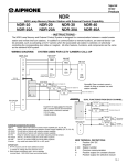
- INSTRUCTIONS The NDR-nRS Lamp Memory System is designed for use with the NE-NVP-RA Rescue Assistance sub stations.
The NE-NVP-RA provides communication and call status indication for applications with ADA requirements for
Areas of Rescue Assistance. The NE-NVP-RA features Braille signage, a large red call button, and "call placed"
and "help coming" LED indicators. The sub station flush mounts into a 3-gang masonry-type box, or surface
mounts in the SBX-NVP. Tamper proof screws are provided, along with a wrench for installation. Remote lamps
can be added for better visibility of a station's status. The NDR-nRS master station is equipped with a door
release button and a reset button to reset calls at the master station. The NDR-nRS has outputs to activate an
external device, such as a CCTV camera when the associated sub station is selected, or selectively controlling
the corresponding door strike or maglock.
WIRING DIAGRAM:
SYSTEM USED FOR CCTV CAMERA CALL-UP
NDR-20RS
NE-NVP-RA
NE-NVP-RA
NE-NVP-RA
1
2
3
~
20
Red
Red
Red
Green
jumper
Green
jumper
Blu
Pur
Blk
Yel
Org
E
S
H
Green
jumper
Blu
Pur
Blk
Yel
Org
Leave green
jumper intact
Blu
Pur
Blk
Yel
Org
External
Terminal Block
1
BLK
RY-PA
YEL
BLK
#2
2
3
~
20
PS-2410A
+
-
+
-
BLK
L
RY-PA
#1
YEL
RY-PA
#3
YEL
Closure for Station #2
Normally Open contacts remain
closed as long as master has sub
station selected.
Closure for Station #3
Terminal Block
Equipment for each station that requires
both a constant closure and momentary
closure when a channel is selected:
2 RY-PA relays
1 Diode (1N4001)
Individual Components for System:
NDR-nRS Master station with selective contact output capability (10, 20, 30, 40)
NDR-nARS Master station w/hndst andcontact output capability (10, 20, 30, 40)
ND-20AS 20-call Add-on Selector with selective output capability (Require PS-2410A)
ND-40AS 40-call Add-on Selector with selective output capability (Requires PS-24E)
RY-PA
Relay for selective output (1 per station requiring external contact)
PS-2410A24V DC, 1A Power Supply for 10-20 station systems
PS-24E
24V DC, 2A Power Supply for 30-40 station systems
NE-NVP-RA Vandal proof sub station with call status indicators and braille signage
IMPORTANT:
1. RY-PA must be used for each additional contact
to isolate AC voltage from the intercom circuit.
2. Extra contact connections and L are on separate
terminal block. NDR-30/40RS have two terminal blocks.
Closure for Station #1
DUAL FUNCTIONS FROM EACH CHANNEL:
1
BLK
L
BLK
RY-PA
#1
YEL
Momentary closure #1
RY-PA
#2
YEL
Constant closure #1
BLK
RY-PA
YEL
#1
Momentary
closure #2
BLK
RY-PA
YEL
#2
Constant
closure #2
2
NDR-RS Master
H
NDR-RS TERMINAL DEFINITIONS:
+
Positive 24V DC
Negative
1~40
Station number
E
Common communication
S
Sends "call placed" tone to sub
H
Resets call signals at sub when RESET
button is pressed.
Pg. 1
WIRING DIAGRAM:
SYSTEM USED FOR SELECTIVE DOOR RELEASE
NDR-20A-RS
NE-NVP-RA
NE-NVP-RA
NE-NVP-RA
1
2
3
~
20
Red
Red
Red
Green
jumper
Blu
Pur
Blk
Yel
Org
E
S
H
1
To activate
door release,
press button
located above
TALK button.
+
-
BLK
2
+
-
RY-PA
#1
Blu
Pur
Blk
Yel
Org
Normally Open contacts
are maintained when the
door release button is being
pressed while a station
button is selected.
Closure for Station #2
RY-PA
YEL
#2
Leave green
jumper intact
Blu
Pur
Blk
Yel
Org
Closure for Station #1
BLK RY-PA
#3
Closure for Station #3
YEL
L
External
Terminal Block
Green
jumper
YEL
BLK
3
~
20
PS-2410A
Green
jumper
Common for each closure
To convert RY-PA to N/C
(normally closed) contact:
Move one yellow wire from
"NO" to "NC". (Internal
connection, soldering
required.)
x
x
AC Power
for Door
Releases
OPERATION:
* POWER SWITCH MUST BE ON FOR SYSTEM TO BE OPERABLE.
1. When a station calls in, press the selector button corresponding to the lit LED.
2. To speak to the person at the remote station, press the TALK button or pick up the handset. Release TALK
button to hear reply. Communication via the handset is VOX (voice actuated).
3. If the extra contacts are used as shown in the "camera call-up" diagram, activating a device that is to remain
on for the duration of the call, the station's relay will stay activated as long as the selector button is depressed.
4. If the extra contacts are used as shown in the "selective door release" diagram, press the "door release" button
while the selector button is depressed. This will activate the corresponding relay as long as the button is being
pressed, which will activate the door release mechanism.
5. When the conversation is completed, press the OFF button to the left of the station selector button.
Hang up handset.
SPECIFICATIONS
Power Source:
Commun. Output:
Communication:
Calling:
Wiring:
Wiring Distance:
24V DC at master. Use PS-2410A (NDR-10, 20) or PS-24E (NDR-30, 40).
500mW at 20 ohms
Push-to-talk, release-to-listen (TALK button) or VOX handset at master.
Hands free at sub station.
Master to sub: By voice only after pretone.
Sub to master: Call button on sub activates tone and LED at master,
remaining active until answered.
2 conductors homerun to sub station, or loop multi-conductor with 1 common
+ 1 individual wire per sub station on wire run.
Separate 2 conductor from RY-PA to external device.
Shielded cable is recommended. Use Aiphone #822202 (22AWG)
or #821802 (18AWG) wire (2 cond.).
420' with 22AWG; 1,000' with 18AWG.
Aiphone Communication Systems
1700 130th Ave. N.E.
Bellevue, WA 98005
(425) 455-0510
FAX (425) 455-0071
For additional information about this system,
please refer to the standard NEM instructions.
Toll Free Technical Support
Phone: 1-800-692-0200
FAX: 1-800-832-3765
Pg. 2
NDR-RS Instr.
1098bkjd