1
92101 0705
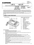
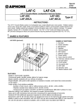
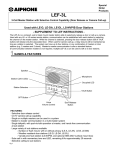
LAF-C Console Master Loudspeaker Intercom System
Type F
- INSTRUCTIONS The LAF-C Console Master system is a loudspeaker type, single talkpath open voice system. Multiple masters
can be used, along with a large variety of sub station models to create a communication system tailored to the
user's needs. Master stations are available in 20-and 40-station sizes, with or without a handset. For greater
capacity, include a 20- or 40-station add-on selector. Any "LE-" or "LS-" series sub station can be used.
All Call and/or Background Music are optional features requiring additional equipment (BG-10C, PS-1225UL).
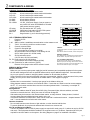
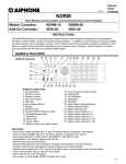
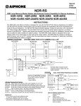
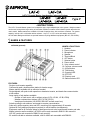
NAMES & FEATURES
LAF-20CA (pictured)
NAMES & FUNCTIONS:
1. Handset
2. Power indicator
3. Microphone
4. Speaker
5. Terminal Block
6. OFF button
7. Selector button
8. Power switch
9. Voice volume control
10. Call tone volume control
11. All Call button
12. TALK button
13. Occupied LED
14. OFF LED
15. Directory card
16. Station selector LED
FEATURES:
· Single or multi-master capability
· Commercial grade, durable master station for heavier usage
· Master stations available with or without a handset
· Single talkpath, with push-to-talk operation or handset at master, and hands free communication
at sub station
· Large variety of sub stations available
- Surface or flush mount, with or without privacy (LE-A, LE-AN, LE-B, LE-BN)
- Weather resistant door stations (LE-D, LE-DA, LE-DL)
- Vandal proof sub station (LS-NVP/B, SBX-NVP surface mount box)
· Selective calling to sub stations, and master-to-master communication
· Subs call in with momentary tone and LED, remaining lit for approximately 20 seconds
· Optional All Call (additional equipment required) to call all stations simultaneously
· Equipment used for All Call also allows for background music to be heard through master and subs
· Master is desk or wall mountable. LAF-20CA can be rack mounted in RMK-01 rack mount kit.
LAF-20C can be rack mounted in RMK-03 rack mount kit.
· 20- and 40-call add-on selectors available, with LA-40AS rack mountable with RMK-02.
Pg. 1
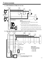
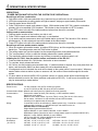
COMPONENTS & WIRING
Individual Components for System:
LAF-20C
20-call console-style master station
LAF-20CA
20-call console-style master station with handset
LAF-40C
40-call console-style master station
LAF-40CA
40-call console-style master station with handset
LA-20AS
20-call Add-on Selector
LA-40AS
40-call Add-on Selector
PS-1225UL
12V DC, 2.5A Power Supply. One per system, or
one per BG-10C when All Call/Music is included
(also powers intercom system)
LE-series
Any sub station with "LE-" prefix
LS-NVP/B
Vandal proof sub station for LAF-C/CA system
SBX-NVP
Surface mount box for LS-NVP
SA-1
Surge Arrestor (1 per 2 wires being protected)
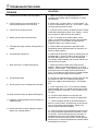
LAF-20C/CA terminal block
+
-
E
E
E
E X1 X2 X3 X4
C
R
Y P1 P2 P3 X5 X6 X7 X8
LAF-C TERMINAL DEFINITIONS:
10 9 8 7 6 5 4 3 2 1
+
Positive 12V DC
Negative
20 19 18 17 16 15 14 13 12 11
1~40 Station number, establishes communication to other master or sub
C
"CALL", for receiving a call from another master
TRANSMIT
RECEIVE
E
Common communication
JUMPERS:
R
Control for Occupied light
In multi-master system, remove E/- jumper at master and
("R" is grounded when system is occupied)
sub stations.
When add-on selector is included, remove X2/X3 jumper.
Y
All Call override control of station in use during All Call
(9V DC when system is in All Call mode)
INTERNAL CONTROLS:
P1
All Call activation control
VOX. SENSITIVITY: Potentiometer is located inside unit
behind handset. Adjust for sensitivity of VOX circuit.
(10V DC when All Call is activated)
P2, P3 Audio output for All Call initiation
CALL TONE WHILE MONITORING:
On the main PC board, there is a jumper labeled W1.
(Voice transmit from master initiating All Call)
With this in place, the incoming call tone will be muted if
X1~X8 Connection for add-on selector (Type E)
any master in the system is in the Occupied mode. If call
tone is desired while Occupied, cut W1 jumper.
Remove X2/X3 jumper when add-on selector is used.
WIRING & INSTALLATION:
Before Installation:
· Make sure you have the proper power supply(ies) and all necessary and compatible equipment for the system.
· All Call and/or background music are optional features which require additional equipment. See notes below.
· Lay out your system in advance, assigning station numbers for all sub station locations.
· Surge protection for the intercom equipment is strongly recommended. Add SA-1 surge arrestors for the power
supply, plus one per two wires connected to the master station. See diagram on page 3.
Wire:
· Shielded wire is recommended. Use the proper gauge for the distance being run.
· Wiring between masters must be a multi-conductor cable. If more than one cable is used to connect masters,
the "E", "C", and number terminal wires must be in the same jacketed cable. If necessary, run multiple "E"
wires, one in each cable.
Wiring Method:
· Run intercom cables at least 20" away from all AC wiring, fluorescent lights, dimmer switches, and other
electrical or electronic devices. Wiring can cross AC wires at 90 degrees.
· Sub stations may be homerun to the nearest master station, or daisy-chained. If daisy-chained, include 2
common wires plus one individual wire per station on the run.
· In a SINGLE MASTER SYSTEM ONLY: Subs can be wired with 2 conductors homerun. Jumpers between "E"
and "-" must be attached on all subs and at the master.
Intercom Locations:
· Do not install intercoms near dimmer or light switches, or other electrical wall devices.
· To prevent feedback, do not place sub stations back-to-back on a common wall.
All Call and Background Music:
· The BG-10C adaptor and PS-1225UL power supply are required for each group of 11 stations to receive All Call
and music. This equipment should be installed in an equipment room or in a cabinet. Capacitors (NP-25V) are
required for each sub station on the system. See wiring diagram on page 5 for installation information.
Pg. 2
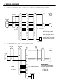
WIRING DIAGRAMS
3a. SINGLE MASTER SYSTEM, NO ALL CALL
SA1
SA-1 for optional
surge protection
(See note #3.)
SA1
LAF-20C
LE-A
1
2
3
4
5
1
LE-A
1
LE-D
1
E
-
E
-
E
-
~
20
E
E
E
E
C
R
Y
P1
P2
P3
+
-
LE-D
1
E
All "E" terminals are
common internally.
NOTES:
Two wiring method can be used:
1. 2 conductor homerun to each sub station from the master.
(Single master system only.)
SA1
2. Run multi-conductor wire in a daisy-chained fashion with 2
common wires (E & -) plus one individual wire per station on the run.
PS-1225UL
Remove jumpers between E & - when daisy-chained method is used.
+
-
3. To protect system from power surge, install SA-1 arrestors at master
station. One SA-1 is required for every two wires connected to master.
3b. DUAL MASTER SYSTEM WITH MASTER-TO-MASTER COMMUNICATION
LAF-20CA
LAF-20CA
LE-DA
1
2
3
1
2
3
1
~
~
19
19
E
20
C
R
Y
P1
P2
P3
E
C
20
R
Y
P1
P2
P3
+
-
+
-
LE-DA
LE-DA
1
1
LE-DA
1
Remove
E/- jumpers
E
-
E
-
E
-
Master-to-master
communication is shown
on channel 20 of each
master.
Y, P1, P2, P3
terminals used only if
All Call Adaptors are
included.
+
-
PS-1225UL
WIRING NOTE:
The following sub stations
are wired as shown above:
· LE-A, LE-AN
· LE-B, LE-BN
· LE-D, LE-DA
RY-AC for external signalling
when sub calls
Blk
Red
Wht
E
-
RY-AC
Yellow
To external signalling device and power
(E.g. Station #19 will actvate ext. device
when it calls in to master.)
Pg. 3
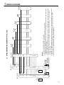
WIRING DIAGRAMS
3c. THREE MASTER STATIONS WITH SUBS WIRED TO DIFFERENT MASTERS
LAF-40CA
Remove
E/- jumpers
Red
1
2
3
~
~
~
37
37
37
E
C
39
40
R
Y
P1
P2
P3
E
38
C
40
R
Y
P1
P2
P3
E
38
39
C
R
Y
P1
P2
P3
+
-
+
-
+
-
LS-NVP
Blk
Grn
LS-NVP
1
2
3
Red
Blk
Grn
LAF-40CA
1
2
3
LS-NVP
Red
LAF-40CA
LS-NVP
Red
Blk
Grn
Blk
Grn
Master-to-master
communication
NOTE:
When wiring LS-NVP
subs with two wires,
black and green wires
are tied together at sub,
and "E" and "-" terminals
are jumpered at master.
+
PS-1225UL
3d. MASTER STATION WITH ADD-ON SELECTOR
LE-DA
LA-40AS
LAF-20CA
LE-D
1
1
2
3
1
2
3
1
LE-DA
~
~
1
40
20
E
-
1
LE-D
1
E
-
E
-
LE-D
E
-
E
-
E
-
R
NOTE:
LA-20AS wires
the same as
shown here.
Blk
Yel
Org
Gry
Brn
Red
Wht
Grn
X1
X2
X3
X4
X5
X6
X7
X8
PS-1225UL
+
-
+
-
Wiring from
Add-on Selector
WIRING NOTE:
The following sub stations
are wired as shown above:
· LE-A, LE-AN
· LE-B, LE-BN
· LE-D, LE-DA
Pg. 4
+
-
PS1225UL
R
E
L
E
R
E
L
E
+
-
DC IN
E
+
R
Y
P1
P2
P3
11
AUX
+
-
PS1225UL
NP-25V
AUX
+
-
DC IN
E
+
R
Y
P1
P2
P3
1
2
~
10
BG-10C #2
To AUX (10K
ohm) output of
music source
E
-
1
LE-BN
E
-
1
LE-BN
E
-
1
LE-BN
E
-
1
LE-BN
E
-
1
LE-BN
E
-
1
LE-BN
NOTES:
1. Any LE- or LS- series sub station can be used.
2. Capacitor for All Call is Aiphone model NP-25V: 33µfd, 25V, non-polarized.
Capacitor must be inserted in series between BG-10C and the number terminal on the master station that is
wired to a standard sub station.
3. Background music can be distributed throughout the system via the BG-10C(s). Music source must provide
an AUX (10K ohm) output. Music is distributed to the master station through the "C" terminal, showed
wired to "11" above.
4. Each BG-10C can provide music and/or All Call to as many as 11 sub or master stations. Include as many
adaptors and power supplies as necessary to provide enough outputs to the stations in the system.
5. Do not connect "+" terminal between multiple BG-10C adaptors.
E
+
R
Y
P1
P2
P3
1
2
3
~
10
11
12
~
20
C
1
2
~
10
NP-25V
LAF-20CA
BG-10C #1
3e. SINGLE MASTER SYSTEM WITH ALL CALL
WIRING DIAGRAMS
Pg. 5
OPERATIONS & SPECIFICATIONS
OPERATIONS:
* POWER SWITCH MUST BE ON FOR THE SYSTEM TO BE OPERATIONAL.
Receiving a call from a sub station:
1. Sub station calls in with mono-electronic tone, heard as long as call button at sub is depressed.
2. LED light corresponding to calling station will light at master, staying on approximately 20 seconds.
3. Depress station button with lit LED.
4. Press TALK button to speak, and release to listen. With handset model (LAF-CA), speak to sub station
privately with voice actuated (VOX) handset. TALK button is also functional on LAF-CA models.
5. Press OFF button to the left of the station selector button when the call is concluded.
Calling a sub or master station:
1. Depress station number of the location you wish to call.
2. Press TALK to speak, and release to hear reply, or use handset.
3. If you wish to send a pre-announce tone to the called station, press the TALK and ALL CALL buttons
simultaneously. A mono-electronic tone will be heard at the called station.
4. Press OFF button to the left of the station selector button when the call is concluded.
Receiving a call from another master station:
1. When one master calls another master, no station LEDs light up, and the responding master answers back
hands free. The calling master uses the TALK button to speak.
2. The calling master can use the handset, but the responding master must speak hands free.
3. The "occupied lamp" will be on while the initiating master has a station selected.
4. The responding master should not press any buttons to respond to another master's call.
Initiating an ALL CALL from the master station, and features of the BG-10C:
1. Press and hold the black ALL CALL button, then make an announcement.
2. To conclude, simply release the button.
3. All Call is a one way outgoing announcement only. If a station wishes to respond, they must press their call
button, and the master station can then answer the call as described above.
4. If background music is included, the music will be heard on the system while it is not occupied. When any
master station selects a station to place or answer a call, the music will be muted throughout the entire
system.
5. If a door station is wired to the BG-10C to produce a chime, a 4-stroke chime will be heard through the
stations selected to receive the chime (switches under plate on BG-10C). A call from a door station can
only be answered by a master station.
SPECIFICATIONS:
Power Source:
12V DC at master. Use one PS-1225UL per system,
or one PS-1225UL per BG-10C when All Call is included.
Communication Output: 800mW at 20 ohms (receive); 500mW at 20 ohms (transmit)
Communication:
Push-to-talk, release-to-listen (TALK button), or VOX handset at master.
Hands free at sub station.
Calling:
Master to sub or other master: By voice (TALK) or tone (TALK & ALL CALL simult.)
Sub to master: Call button on sub activates tone and LED at master,
remaining lit for approximately 20 seconds.
Wiring:
2 conductors homerun to sub station (1-Master system only), 3-conductor, or loop multiconductor with 2 common + 1 individual wire per sub station on wire run.
Shielded cable is recommended.
Single Master Systems without BG-10C:
Aiphone #822202, 2 cond. 22AWG; #821802, 2 cond. 18AWG
Multi-Master System (Can also be used in a single master system or systems with BG-10C):
#822203, 3 cond. 22AWG; #822206, 6 cond. 22AWG.
LAF-C to ea. BG-10C: Aiphone #822220, 20 cond. 22AWG.
Wiring Distance:
650' with 22AWG; 1,600' with 18AWG.
Dimensions:
LAF-20C: 10-1/4" x 13-1/2" x 5-1/2".
LAF-20CA: 10-1/4" x 17-3/4" x 5-1/2"
(H x W x D)
LAF-40C: 10-1/4" x 19-1/2" x 5-1/2".
LAF-40CA: 10-1/4" x 23-1/2" x 5-1/2"
LA-20AS: 10-1/4" x 7" x 5-1/2".
LA-40AS: 10-1/4" x 12-7/8" x 5-1/2".
Pg. 6
TROUBLESHOOTING GUIDE
PROBLEM
SOLUTION
1. No call tone or LED when sub calls master.
1. Make sure jumper is installed between E & terminals at the master and all sub stations (in 2-wire
configuration).
2. Call tone works, but no communication, or
communication works, but no call tone.
2. Same as #1 in 2-wire system. In 3 wire system, 1 &
E are for communication, and 1 & - are for call-in. Check
continuity and connection of wires.
3. Call tone is too loud or too quiet.
3. Call tone volume control is located on main PC board
under select switch panel (white 3-pos. switch). Level is
set to maximum. Move to mid or low position.
4. Master stations cannot call each other.
4. The "C" terminal on the master station means
"CALL", and provides master-to-master communication.
Make sure the "C" of one master is connected to a
designated station # on another master.
5. LED lights don't light up when calling master-tomaster.
5. Station LEDs only light when a sub station calls.
Responding master answers hands free, therefore not
having to select a station.
6. Occupied light is always on.
6. Make sure all black OFF buttons on master(s) are off
(pressed down). Check "R" wire for short to ground. If
occupied light remains lit with "R" wire disconnected
from master, internal damage has occured, and the unit
must be sent in for repair.
7. When subs call in, multiple LEDs light up.
7. Make sure station number wires aren't shorted
together. Remove all jumpers between E & - in multimaster or 3-wire system. Test master by taking wires off
# terminals, then momentarily shorting # terminal to (neg). If more than one light comes on, internal damage
has occured, and the master must be repaired.
8. All Call doesn't work.
8. All Call is an optional feature requiring a BG-10C and
PS-1225UL for every 10-11 stations in the system.
Make sure adaptors are wired properly. See diagram
#3e.
9. All call doesn't work, but adaptors are included.
10. When All Call is made, all station LEDs light up.
11. Feedback is heard between intercom stations in
adjacent rooms.
12. System has AC hum when listening to another
station from a master station.
9. Check connection of P1, P2, P3 terminals between
master and BG-10C's. P1 should read at least 10V DC
when All Call button is pressed. Voice is carried on P2,
P3 wires.
10. If single-call sub stations are used, NP-25V
capacitors must be installed as shown on diagram #3e.
11. Intercom stations should not be mounted back-toback on a common wall. Separate them by at least two
feet, or on separate walls if possible. Adjust voice
volume control to eliminate feedback.
12. Intercom wiring must be at least 20" away from any
AC wiring, fluorescent lights dimmer switches, or other
AC devices. Cross at 90 degrees when necessary. If
shielded wire was used, tie all shields together and
ground at one end to an earth ground. If noise persists,
isolate source of noise and separate the intercom station
and wiring from the source.
Pg. 7
PRECAUTIONS & WARRANTY
CAUTION
* Do not connect any AC wires to any terminal on any unit, as fire or unit damage may occur. Connect only
specified power source on +, - terminals.
* Do not install more or different power sources than specified for the system.
* Do not attempt to install or connect wires on LAF-C system while the system's power supply is plugged in.
* LAF-C masters and related equipment, unless specified as "weather resistant", are designed for indoor use only.
Door stations (LE-D, LE-DA, LE-DL) may be installed outdoors.
IMPORTANT
* There is no need to disassemble the equipment for installation. Call tone volume and handset vox sensitivity
adjustments are inside the master station, and are the only controls to be accessed inside the unit. Do not access
the PC boards inside the units unless properly qualified.
* Any other manufacturer's products installed with the system (power supply, external signalling device, etc.) are not
covered under Aiphone's warranty.
* Do not mount LAF-C equipment in the following places, as it may cause the system to malfunction:
- High or extreme cold temperature areas: under direct sunlight, near equipment that varies in temperature,
front of air conditioner, inside a refrigerated area, etc.
- Places subject to moisture or humidity extremes.
- Places subject to environmental conditions, such as dust, oil, chemicals, salt, etc.
in
* LAF-C units are electronic devices, which must not be subjected to water or any other liquid.
* Severe weather conditions, such as lightning storms, may cause damage to LAF-C equipment. We recommend
that power surge protection be installed to minimize potential component level damage.
- Install the SA-1 surge arrestor as shown to protect the power supply from a surge.
- Additional SA-1 surge arrestors should be installed on all communication lines (one SA-1 for every two wires
connected to master.) See diagram #3a.
LAF-C Master
PS-1225UL
+
-
+
SA1
Earth Ground
WARRANTY
Aiphone warrants its products to be free from defects of material and workmanship under normal use
and service for a period of one year after delivery to the ultimate user and will repair free of charge or
replace at no charge, should it become defective upon which examination shall disclose to be defective and
under warranty. Aiphone reserves unto itself the sole right to make the final decision whether there is a
defect in materials and/or workmanship; and whether or not the product is within the warranty.
This warranty shall not apply to any Aiphone product that has been subjected to misuse, neglect,
accident, or to use in violation of instructions furnished, nor extended to units which have been repaired or
altered outside of the factory. This warranty covers bench repairs only, and any repairs must be made at the
shop or place designated in writing by Aiphone.
Aiphone will not be responsible for any costs incurred involving on-site service calls.
Aiphone Communication Systems
1700 130th Ave. N.E.
Bellevue, WA 98005
(425) 455-0510
FAX (425) 455-0071
Toll Free Technical Support
1-800-692-0200
TOLL FREE FAX LINE:
1-800-832-3765
E-Mail: [email protected]
Pg. 8
LAF-C Instr.
Lit #92101
0705JS