1
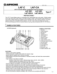
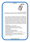
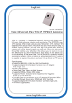
1205
10 Camera Adaptor for LEF/LDF System
- INSTRUCTIONS The MYW-P10L adaptor allows up to 10 2-wire video door stations to be used with the LEF series Master
Sentry System. MY or MK PanTilt series video door stations may be used with the MYW-P10L. CCTV
cameras may be connected through the MYW-P10L using the MYW-MD/B adaptor. Door release is
available through the intercom system (LEF or LDF only).
WIRING DIAGRAM:
MYH-CU
MYH-CU
B1
B2
A1
A2
U1
U2
A1
A2
B1
B2
U1
U2
MYW-P10L TERMINAL DEFINITIONS:
MYW-P10L
B1
B2
1A1
1A2
+
-
U1
U2
+
-
To: Monitor TV
and/or Time-Lapse
VCR, ect.
(525) line only
+18V
-18V
4A1
4A2
To Strike
& Power
#5
Yellow
Yellow
RY-PA
RY-PA
Black
Black
K1
K2
K3
K4
K5
~
K10
To Strike
& Power
#4
Black
+12V
-12V
To Strike
& Power
#3
RY-PA
PS-1225UL
To Strike
& Power
#2
Yellow
L
K1
K2
K3
K4
K5
~
K10
To Strike
& Power
#1
Black
L
K1
K2
K3
K4
K5
~
K10
Video activation
to monitors
18V+
18V-
Positive 18V DC
Negative
N1,N2
Unused
Found in external terminal box
1 ~ 10
Audio communication
E
Common communication
12V+
12V-
Positive 12V DC
Negative
K1 ~ K10 Video control terminals
E
+
-
U1
U2
EXTERNAL TERMINAL BLOCK
RY-PA
+
-
INSIDE MYW-P10L CHASSIS
Yellow
+
-
MK-DGC
A1
A2
5A1
5A2
~
10A1
10A2
1
2
3
4
5
6
7
8
9
10
MK-DBC
A1
A2
Black
1
2
3
4
5
6
7
8
9
10
C
E
R
Y
MK-DBC
A1
A2
RY-PA
1
2
3
4
5
6
7
8
9
10
C
E
R
Y
Found inside MYW-P10L
nA1
Input from MY/MK Series
nA2
video door station
B1
Video signal output
B2
to monitors
Any MK-series
video door station
is compatible with
this system.
A1
A2
Yellow
LEF-10
MK-DAC
3A1
3A2
CN-9
LEF-10
A1
A2
2A1
2A2
PS-1820UL
+
-
MK-DAC
*
*When using door release relays: Install cathode side of
supplied 1N4007 diodes directly to K terminals of MYW-P10L,
and connect black wire of RY-PA to anode side of diode.
Do not install diodes on K terminals at the LEF master station.
NOTES:
1. The MONITOR button, Auto-Scan
Duration, and Monitor Receive
Volume switches on the front of the
unit are non-functional.
2. Diodes shown must be used
when using RY-PA door release
relays. They are 1N4007, and are
included in the box with the unit.
3. When initializing the MYW-P10L
with CCTV cameras,a constant call
tone will be heard on the LEF
master for approx. 1 minute
during this process. To avoid this,
unplug the PS-1225UL for the LEF
system before turning on the MYWP10L, then plug back in when the
initialization is complete. The
constant tone will also be heard if
the MYW-P10L loses power, or if
it is turned off.
4. Only wiring concerning the MYWP10L is shown here. For complete
installation and wiring information,
please see the standard LEF
instructions.
Pg. 1
OPERATION:
Call-in from a video door station:
1. When a video door station calls in, all monitors in the system will activate, and the appropriate LED will illuminate on
the LEF master. The call tone will be heard until the call is answered or for 5 seconds, whichever comes first.
The monitor will turn off in 45 seconds if the call is not answered. The LED will remain lit for approximately 20
seconds after the tone is no longer heard.
2. While the monitor is active, the PanTilt button may be used to control the camera position (PanTilt cameras only.)
3. If the door is not selected within 45 seconds, the monitor will turn off. Communication and video can be
established by pressing the appropriate selector button on the LEF master.
4. When called by a door station while communicating, only the LED will activate. Press the OFF button to
end the existing conversation, then select the door button to establish communication and video.
Monitoring a door station:
1. On the LEF master, press the selector button of the door that you wish to monitor.
2. Video monitor will turn on showing the selected door, remaining active for approximately 2-1/2 minutes.
3. Communicate with the door using the LEF master station.
4. Press the OFF button on the LEF master to end the conversation.
Initializing the system:
10
9
8
7
6
5
4
3
2
1
If the MYW-P10L is used with CCTV cameras and MYW-MD/B's, the unit must be initialized before operation.
To initialize the system:
(A) To avoid constant call tone on the LEF during this process, unplug PS-1225UL power supply.
1. Turn power switch on the MYW-P10L OFF.
2. Turn switches associated with CCTV camera locations to ON position.
Set switches located inside bottom of unit.
(For example if stations 4, 5, 6 are
CCTV cameras, set switches 4, 5, and 6 to ON.)
Off
3. Turn MYW-P10L power switch ON.
On
4. Wait for red STANDBY light to go out.
Off
(STANDBY light is located on the face of the unit.)
5. Turn switches associated with the camera locations back to the OFF position.
6. The system is now operational.
Pre-Tone On/Off
When a door station is selected, a short pre-tone will be heard. This pre-tone can be turned off:
1. Remove top left cover of MYW-P10L.
2. Move the second switch from the left to the OFF position.
Reset switch
If the MYW-P10L malfunctions, press the reset switch located under the top left coverplate of the MYW-P10L.
SPECIFICATIONS:
Power Source:
Calling:
18V DC. Use PS-1820UL for every 3 video components.
Electronic call tone and LED on LEF master. Call tone remains active for 5 seconds. LED
remains activated for 25 seconds, or until the call is answered, whichever comes first.
Monitors stay activated for 45 seconds.
Monitoring:
Select door station to monitor using LEF master.
Monitors are active for 2-1/2 minutes.
Wiring Distance:
MYW-P10L to MK series Video door station: 330' using 18 AWG
MYW-P10L to farthest MY series monitor: 245' using 18 AWG
MYW-P10L to farthest LEF-10: 650' using 22AWG; 1600' using 18AWG
Dimensions (HxWxD): 4-1/2" X 7-11/16" X 9"
Weight:
3.31 lbs. (Approx.)
Aiphone Communication Systems
1700 130th Ave. N.E.
Bellevue, WA 98005
(425) 455-0510
FAX (425) 455-0071
Toll Free Technical Support:
1-800-692-0200
FAX: 1-800-832-3765
E-mail: [email protected]
Pg. 2
MYW-P10L/A Instr.
1205JDJS