1
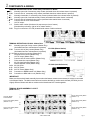
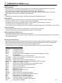
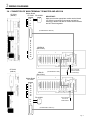
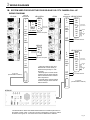
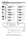
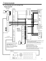
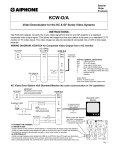
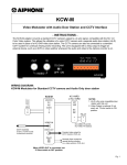
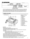
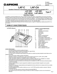
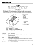
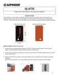
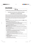
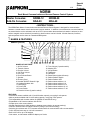
1103
Special
Order
Products
NDRM
Rack Mount Communication and Access/Camera Control System
Master Consoles:
Add-On Consoles:
NDRM-12
NDA-20
NDRM-20
NDA-40
- INSTRUCTIONS The NDRM Rack Mount Communication and Access/Camera Control System is designed for communication
between a central master console and remote intercom stations. In addition to communication to remote locations,
an external device can be activated, such as a CCTV camera when the associated sub station is selected, a door
strike or maglock can be selectively controlled, or both functions can be included. All other features, functions,
and components are the same as a standard NEM system.
1 NAMES & FEATURES
NDRM-20 (pictured)
1
2
3
4
5
6
7
8
27
26
25
24
23
9
10
11
12
13
14
15
16
17
NAMES & FUNCTIONS:
1. All Call Volume
2. Transmit Volume
3. Receive Volume
4. Call Tone Volume
5. LED Test
6. Door Release Button
7. Speaker
8. Directory Card
9. Handset ON/OFF Button & Light
10. Handset/Headset Jack
11. Microphone
12. Power LED
13. Power Switch
14. Receive Volume (3 postion switch)
18
19
20
21
22
15. Tone Volume (3 postion switch)
16. Monitor LED
17. All Call Button
18. Talk Button
19. Off Button
20. Reset Button (optional feature)
21. Station Selector Switch
22. Station Selector LED
23. Station select switches 1~4
24. Station select switches 5~8
25. Station select switches 9~12
26. Station select switches 13~16
27. Station select switches 17~20
FEATURES:
• Rack mount master available with 12, and 20 station capacity, occupying 3 rack spaces
• Add-on panels available with 20 or 40 station capacity, occupying 3 rack spaces
• Field expandable with 4 station add-on kit (NDRM-12 and NDA-20 only)
• Expandable to 100 intercom stations with All Call
• Simplex open voice communication
• Modular handset jack for VOX handset or headset communication to remote station(s)
• Intercom channels with LED status indication (calling in and communicating)
• Selective door release and CCTV camera activation while in communication with a remote station
• Call-in LED and tone stay on until call is answered
• Built-in All Call for up to 100 stations
• One master, or dual master w/NEW-5 adaptor per 5 subs
Pg. 1
Const
Moment
2 COMPONENTS & WIRING
TERMINAL DEFINITIONS CP-544 - Sub & Relay connection PC Board:
NO
Normally open side of momentary relay contact (activated when door release button is pressed)
COM Common side of momentary relay contact (activated when door release button is pressed)
NC
Normally closed side of momentary relay contact (activated when door release button is pressed)
NO
Normally open side of maintained relay contact (activated when station button is selected)
COM Common side of maintained relay contact (activated when station button is selected)
E
Common side of voice communication
H
14V DC output
1~4
Station select number (Numbered in sequence per size of master)
(Numbered top to bottom, right to left on master station.)
CN51 Plug for connection to CP-530 (located inside master or add-on selector)
TERMINAL DEFINITIONS CP-543A - Mother Board (Master and Add-On):
NO
Normally open side of relay contact (Master Only)
(Activated when Door release button is pressed)
CP-543A (Master Station)
COM Common side of relay contact (Master Only)
(Activated when Door release button is pressed)
X1~X8 Add-on selector connection (Master Only)
Q
Occupied circuit control (Master Only)
H
14V DC output (Master Only)
E
Common side of communication (Master Only)
S
Chime extension output (Master Only)
B
All Call signal activation (Master Only)
Y
Internal amplifier control (Master Only)
CP-543A (Add-On Selector)
Vn/An All Call Circuit
A+/A- 24V DC Power
B+/B- 24V DC Power (Master Only)
CN1
Connection to NDRM master unit (Master Only)
CN1
Connection to NDA Add-on unit (Add-On Only)
IMPORTANT!
Make sure that terminal board assembly that contains the Master mother terminal board (CP-543A) is connected
to the Master Station. The Add-on terminal board contains the Add-on mother terminal board (CP-543A), but it is
slightly different. Master and add-on mother terminal boards are NOT interchangeable.
TERMINAL BOARD ASSEMBLY LAYOUT:
(NDRM-20 Shown)
CP-544 Sub & Relay Board
(Stations 1~4)
CP-543A Mother
Terminal Board
CP-544 Sub & Relay Board
(Stations 13~16)
CP-544 Sub & Relay Board
(Stations 5~8)
CP-544 Sub & Relay Board
(Stations 17~20)
CP-544 Sub & Relay Board
(Stations 9~12)
7"H x 19"W x 2"D
Pg. 2
2 COMPONENTS & WIRING (Cont.)
WIRING & INSTALLATION:
Before Installation:
· Make sure you have the proper power supply(ies) and all necessary and compatible equipment for the system.
· Background music is optional and requires additional equipment. See notes below.
· Lay out your system in advance, assigning station numbers for all sub station locations.
· Surge protection for the intercom equipment is strongly recommended. Add SA-1 surge arrestors for the power
supply, plus one per two wires connected to the master station.
Wire:
· Shielded wire is strongly recommended. Use the proper gauge for the distance being run.
Wiring Method:
· Run intercom cables at least 20" away from all AC wiring, fluorescent lights, dimmer switches, and other
electrical or electronic devices. Wiring can cross AC wires at 90 degrees.
· Sub stations may be homerun to the master station, or daisy-chained. If daisy-chained, include one
common wires plus one individual wire per station on the run.
· If more than one master is used, homerun sub to the NEW-5 Dual Master Adaptors, then wire NEW-5's to each master.
Intercom Locations:
· Do not install intercoms near dimmer or light switches, or other electrical wall devices.
· To prevent feedback, do not place sub stations back-to-back on a common wall.
Mounting the Master & Add-On Units:
· Each master and add-on requires three rack console spaces.
· Secure the masters and add-on stations using the included screws. See information provided with your rack console for
more detailed information.
Mounting the terminal board:
· Make sure that the appropriate terminal board assembly is used for the master and add-on selector(s). Master and
add-on mother terminal boards mounted on terminal board assembly are different and are NOT interchangeable.
· Secure the terminal board inside the rack console using the supplied screws
· Terminal board must be mounted within 5' of the master and add-on units, connected with ribbon cables.
Individual Components for System:
NDRM-12
12-call Master Station
NDRM-20
20-call Master Station
NDA-20
20-call Add-on Selector
NDA-40
40-call Add-on Selector
NDI-4S
4-Station selector add-on kit (NDRM-12 or NDA-20 can be expanded to 20 and
40, respectively)
TBP-6
Terminal Back Plate for up to 6 terminal boards
PS-2420UL
24V DC, 2A Power Supply (1 per master and 1 per each add-on panel)
NE-NVP/B
Vandal proof sub station
NE-NVP-RA
Vandal proof sub for Areas of Rescue Assistance
NE-NVP-2DC Vandal proof sub station with standard and emergency DPDT call button
NE-SS
Vandal proof sub station, 2-Gang
NE-SSR
Vandal proof sub station with red mushroom push button, 2-Gang
NE-JA
Flush mount door station with stainless steel cover
NE-DA
Surface mount door station
NA-NE
Flush mount sub station with aluminum faceplate
NA-A
Wall/Desk mount sub
NA-AN
Wall/Desk mount sub with privacy
NA-T/A
Handset Sub Station
SBX-NVP
Surface mount box for NE-NVP/B sub station
SBX-2G
Surface mount box for NE-SS and NE-SSR sub station
NBX-2
Surface mount box for NA-NE sub station
SA-1
Surge Arrestor (1 per 2 wires being protected)
NEW-5
Dual Master Adaptor (1 per 5 sub stations)
PS-1225UL
12V DC power supply for NEW-5 (1 per 5 NEW-5)
NB-U
Background Music Adaptor
Pg. 3
3 WIRING DIAGRAMS
3A. CONNECTION OF MAIN TERMINAL TO MASTER AND ADD-ON
CP-543A
(Master)
Mother Board
CP-543A PS-2420UL
A+
A-
+
-
BB+
IMPORTANT!
Make sure that the appropriate mother terminal board
(CP-543A) is connected to the master and add-on
selector(s). Master and add-on mother terminal boards
are NOT interchangeable.
CN 1
(Included Ribbon cable "M")
Q
H
E
S
B
Y
V1
A1
V2
A2
CP-543A
(Add-on)
NDRM-20
(Back View)
NDA-20
(Back View)
2-pin connector.
Connect to addon selector(s).
(Included Ribbon cable)
Mother Board
CP-543A
V1
A1
V2
A2
V3
A3
V4
A4
A+
A-
PS-2420UL
+
-
2-pin connector.
Connect to
master station.
CN 1
(Included Ribbon cable "A")
Pg. 4
3 WIRING DIAGRAMS
3B. SYSTEM USED FOR SELECTIVE DOOR RELEASE OR CCTV CAMERA CALL-UP
WIRING DIAGRAM:
CP-544A
Intercom
CP-544A #1
NE-NVP-RA
1
E
S
H
H
Moment
NO
COM
NC
Mother
Board
CP-543A*
CP544
Red
Blk
Yel
Org
Grn
Grn
Intercom
CP-544A #2 NE-NVP-2DC/B
5
E
H
Leave green
jumper intact
**strike and power
To
Moment
NO
COM
NC
Red
Blk
Wht
Grn
Grn
Leave green
jumper intact
Blu
Org
Org
Yel
Yel
Contact
#1
Contact
#2
Const
Const
NO
COM
NO
COM
***
To Video Switcher
NE-NVP
2
E
H
Red
Blk
Leave green
jumper intact
Grn
Grn
Moment
NO
COM
NC
**
To strike and power
CN51
To CP-530
(Included Ribbon Cable #1)
6
E
H
Moment
Const
NO
COM
NE-NVP-2DC/B
* Yellow and Orange wires from
NE-NVP-RA connect directly to
master board (CP543) "H" & "S"
terminals.
**Normally Open contacts remain
closed as long as master has sub
station selected and door release
button depressed.
***Normally Open contacts remain
closed as long as master has sub
station selected.
NO
COM
NC
Const
NO
COM
Red
Blk
Wht
Grn
Grn
Blu
Org
Org
Yel
Yel
Leave green
jumper intact
Contact
#1
Contact
#2
***
To Video Switcher
CN51
To CP-530
(Included Ribbon Cable #2)
NDRM-20
* Numbered ribbon cables from NDRM master determine sub station placement on
the master console. Cable 1 connects to CP544 of sub stations 1 through 4, cable 2
for station 5 through 8, etc. Connection is the same for NDA add-on selectors.
Pg. 5
3 WIRING DIAGRAMS
3C. SYSTEM WITH BOTH DOOR RELEASE AND CCTV CAMERA CALL-UP
WIRING DIAGRAM:
CP-544A
Intercom
CP-544A #1
1
E
H
Intercom
CP-544A #2
NE-NVP
Red
Blk
Grn
Grn
Leave green
jumper intact
To strike and power
(Momentary Contact)
NO
COM
NC
To Video switcher
(Maintained Contact)
To Video switcher
(Maintained Contact)
NO
COM
Red
Blk
Grn
Grn
NE-NVP
Leave green
jumper intact
Moment
NO
COM
NC
Red
Blk
Grn
Grn
Leave green
jumper intact
NO
COM
NC
To strike and power
(Momentary Contact)
Const
To Video switcher
(Maintained Contact)
CN51
To CP 530
(Included Ribbon Cable #1)
6
E
H
Moment
To strike and power
(Momentary Contact)
Const
NO
COM
Leave green
jumper intact
To strike and power
(Momentary Contact)
NE-NVP
2
E
H
Grn
Grn
Const
Const
NO
COM
Red
Blk
5
E
H
Moment
Moment
NO
COM
NC
NE-NVP
NO
COM
To Video switcher
(Maintained Contact)
CN51
NOTES:
1. "CONST" Contact on CP544 will be
closed as long as master has sub
station selected.
2. "MOMENT" Contacts connected
directly to CP544 remain closed as
long as master has sub station
selected and door release button
pressed.
To CP 530
(Included Ribbon Cable #2)
NDRM-20
* Numbered ribbon cables from NDRM master determine sub station placement on
the master console. Cable 1 connects to CP544 of sub stations 1 through 4, cable 2
for station 5 through 8, et cetera. Connection is the same for NDA add-on selectors.
Pg. 6
3 WIRING DIAGRAMS
3D. SYSTEM USED WITH LEF-5-NE MASTERS
WIRING DIAGRAM:
Mother Board
CP-543A
Intercom
CP-544A #1
+
-
A+
A-
1
E
H
PS-2420UL
BB+
LEW-5-NE/B
N1
N2
N3
N4
N5
Moment
CN 1
NO
COM
NC
H
Q
Ribbon Cable "M"
Wire each
station to a
designated
number station
as shown here.
Const
NO
COM
To CP-530
(Included Ribbon Cable #1)
Grn
wire
CN51
+
-
* Numbered ribbon cables from NDRM
master determine sub station placement
on the master console.
PS-1225UL
Cable 1 connects to CP544 of sub
stations 1 through 4, cable 2 for station 5
through 8, etc. Connection is the same
for NDA add-on selectors.
1
K1
2
K2
3
K3
4
K4
5
K5
E
R
L
+
-
Blue
Blue
Blu
Pur
Org
Yel
LEF-5-NE
4
E
H
NO
COM
NC
Red
Blk
Gray
NAR-2A*
NO
COM
Moment
D1
D2
D3
D4
D5
NE
Const
H
Q
E
S
B
Y
V1
A1
V2
A2
NE-NVP-RA-LE
L1
K1
L2
K2
L3
K3
L4
K4
L5
K5
LE
RF
* Reset Button:
(Any normally closed
button or keyswitch.
Not required when
resetting the call from
the master.)
NE-NVP-LE
Red
Blk
Pur
Grn
wire
NOTES:
1. "K" Terminal connections are required in this application, with or
without door release being included.
2. Standard NE-NVP/B, NE-NVP-RA or NE-NVP-2DC cannot be
used in a system with the LEF-5-NE Master stations.
Specially modified versions of these units must be used.
The models are identified as:
NE-NVP-RA-LE (for use with LEF-5-NE)
NE-NVP-LE Vandal proof sub for LEF-5-NE
NE-NVP-2DC-LE (for use with LEF-5-NE)
3. For more detailed information, please refer to the instructions
included with the LEW-5-NE and the LEF-5-NE.
NDRM-20
Pg. 7
4 OPERATIONS & SPECIFICATIONS
OPERATIONS:
* POWER SWITCH MUST BE ON FOR THE SYSTEM TO BE OPERATIONAL.
Receiving a call from a single sub station:
1. Sub station calls in with electronic tone, heard until the call is answered at the master.
2. LED light corresponding to calling station will light at master, flashing until the call is answered.
3. Depress station button with lit LED. LED will change from flashing to steady.
4. Press TALK to speak, release to hear reply, or use handset. NOTE: Handset can be used only if the handset is
connected and the HANDSET ON/OFF button is in the ON position (Green LED lit).
5. Press OFF button when the call is concluded.
Receiving calls from multiple sub stations:
1. When multiple sub station calls are received, each calling sub's LED will flash and the electronic tone is heard until
the first call is answered at the master.
2. Depress one of the station buttons with a flashing LED, whichever one is to be answered
3. The call tone will be muted and the answered station's LED will be steadily lit. All other LED's will remain flashing.
4. Press TALK to speak, release to hear reply, or use handset. NOTE: Handset can be used only if the
handset is plugged in and the HANDSET ON/OFF button is in the ON position (Green LED lit).
5. Press OFF button when the call is concluded. Station call light will turn off and communication will be disconnected.
(Important: If OFF button is not pressed and a second station button is selected, both stations will receive outgoing
voice from master)
6. Select the next station with a flashing LED and repeat the steps above.
Activating door release:
1. When a sub station is selected, the "MOMENT" relay is activated when the DOOR RELEASE button is pressed.
2. Door release contact will be active as long as the DOOR RELEASE button is pressed.
Activating a CCTV Camera:
1. When a sub station is selected, the "CONST" relay is activated as long as that station is selected.
2. This relay provides both Normally Open and Normally Closed contacts, depending on the requirements of the other
system.
Calling a sub station:
1. Depress station button of the location you wish to call. A pre-announce, mono-electronic tone will be heard at the
called station.
2. Press TALK to speak, release to hear reply, or use handset. NOTE: Handset can be used only if the handset is
connected and the HANDSET ON/OFF button is in the ON position (Green LED lit).
3. Press OFF button when the call is concluded.
Initiating an ALL CALL from the master station:
1. Press and hold the ALL CALL button, then make an announcement. If the handset is used, speak into the
handset to make the announcement, otherwise, speak into the microphone on the face of the unit.
2. To conclude, release the button.
3. All Call is a one way outgoing announcement only. If a station wishes to respond, they must press their call button,
and the master station can then answer the call as described above.
4. If background music is included, the music will be heard on the system while it is not occupied. When the master
station selects a station to place or answer a call, the music will be muted throughout the entire system.
Initiating a GROUP CALL from the master station:
1. Select the stations that will receive the Group Call.
2. Press TALK to make announcement or use the handset. NOTE: Handset can be used only if the handset is
connected and the HANDSET ON/OFF button is in the ON position (Green LED lit).
3. Press OFF button when the announcement is concluded.
Adjusting System Volume Levels
1. Using a small screwdriver, adjust the overall volume controls located in the upper left corner of the master unit. All
Call, Transmit, Receive, and Tone volumes can all be adjusted independently.
2. Use the three position switch on the front of the master for user control of the Receive and Tone volumes.
Testing LED's
1. Using a small screwdriver, press and hold the LED Test button.
2. All station LED's should illuminate. Any station LED's that do not illuminate must be replaced.
Pg. 8
4 OPERATIONS & SPECIFICATIONS
SPECIFICATIONS:
(Subject to change without notice)
Power Source:
24V DC at master. Use PS-2420UL for master and each add-on selector
Commun. Output:
500mW at 20 ohms
Communication:
Push-to-talk, release-to-listen (TALK button) or VOX handset at master.
Hands free at sub station.
Calling:
Master to sub: By voice only after pretone.
Sub to master: Call button on sub activates tone and LED at master.
Tone remains active until call is answered.
LED is active until call is concluded.
Wiring:
2 conductors homerun to sub station, or loop a multi-conductor with 1 common
+ 1 individual wire per sub station on the wire run.
Separate 2 conductor from each relay contact used on terminal board.
Shielded cable is recommended. Use Aiphone #822202 (22AWG)
or #821802 (18AWG) wire (2 cond.).
Wiring Distance:
420' with 22AWG; 1,000' with 18AWG.
Ribbon Cable:
5' from master or add-on to terminal board
Dimensions:
NDRM-n, NDA-n : 5-1/4" X 19" X 10-1/8"
(H x W x D)
Terminal Board Assembly: 7" x 19" x 2"
WARRANTY
Aiphone warrants its products to be free from defects of material and workmanship under normal use and
service for a period of one year after delivery to the ultimate user and will repair free of charge or replace at
no charge, should it become defective upon which examination shall disclose to be defective and under
warranty. Aiphone reserves unto itself the sole right to make the final decision whether there is a defect in
materials and/or workmanship; and whether or not the product is within the warranty.
This warranty shall not apply to any Aiphone product that has been subjected to misuse, neglect, accident,
or to use in violation of instructions furnished, nor extended to units which have been repaired or altered
outside of the factory. This warranty covers bench repairs only, and any repairs must be made at the shop
or place designated in writing by Aiphone.
Aiphone will not be responsible for any costs incurred involving on-site service calls.
Aiphone Communication Systems
1700 130th Ave. N.E.
Bellevue, WA 98005
(425) 455-0510
FAX (425) 455-0071
Toll Free Technical Support
1-800-692-0200
TOLL FREE FAX LINE:
1-800-832-3765
E-Mail: [email protected]
Pg. 9
NDRM Instr.
1103BKJS