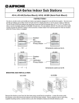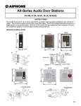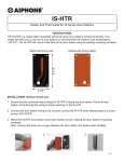
1
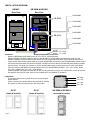
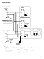
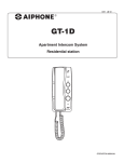
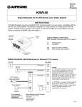
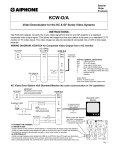
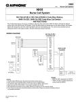
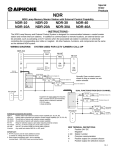
KB-MV2, KB-MV3, KB-SWM, KB-SWS
Color Tilt Multi-Unit Video Entrance System
- INSTRUCTIONS The KB-MV series is a color video multi-unit entry system that can be configured for buildings with two to
twelve tenant locations. Up to three video entrance stations can be used in one system. The color camera can
be tilted upward for a better view of the visitor, and the speaker/microphone provides hands free
communication at the entrance panel. Inside each tenant location, the standard Aiphone KB series audio/video
stations are employed, allowing up to five monitoring locations per tenant. If there are are less than three
common entries, an individual audio-only or audio-video door station can be included for each tenant location.
KB-MV2
KB-MV3
Microphone
Camera Lens
Night Vision LED
Speaker
KB-SWM and KB-SWS
with 2 GF-3P, 1 GF-2F
Open position
for additional
module,
determined by
panel design.
Features:
Streamline design, can be semi flush mounted or surface mounted
Color CCD camera with tilt control
Configure from 2 to 12 call buttons per entry, using 1-, 2-, or 3-button modular panels
Backlit call button directory for easy viewing of names at night
Weather resistant for outdoor use
Hands free communication from entry panel
Automatic night mode LED
Employs KB series room stations
Up to three video entry stations per tenant
Up to five inside stations per tenant
Selective door release from each tenant location when using RY-3DL (one per tenant)
Easy homerun wiring from entry to each tenant using Aiphone series wire # 871802
Page 1
INSTALLATION DIAGRAM:
KB-MV2
Rear View
KB-SWM & KB-SWS
Rear View
To KB-3MRD
U
P
KB-SWM
To KB-3MRD
3A2 3A1 2A2 2A1 1A2 1A1
To KB-3MRD
To KB-3MRD
NOT USED
KB-SWS
To KB-3MRD
3A2 3A1 2A2 2A1 1A2 1A1
To KB-3MRD
WHITE
To + 6VDC
BLACK
To - 6VDC
Installation:
Mount the KB-SWM and KB-SWS into the GF-2F or GF-3F mounting bracket.
Plug the KB-MV2 / KB-MV3 connector cable into the KB-SWM. If any KB-SWS sub-modules are used, plug the
KB-MV2 / KB-MV3 connector cable into the closest one, then plug its blue and yellow 10-pin connector into the next
switch module, daisy-chaining them together. Plug the last KB-SWS connector into the KB-SWM master switch module.
Connect the black and white wire from the KB-MV2 / KB-MV3 connector cable to the SKK-620 power leads (cut spade
lug connectors). The white wire connects to +6VDC (black w/white stripe), and the black wire to -6VDC (solid black).
Connect wires from KB-3MRD’s to corresponding terminals on the KB-SWM / KB-SWS. (1A1, 1A2 = upper button,
2A1, 2A2 = middle button, 3A1, 3A2 = lower button)
Install completed entry panel into either the GF-2B / GF-3B (semi-flush mount) or GF-nHB (surface mount) as required.
Use Aiphone series wire 871802. Wire must be 18AWG solid, non-shielded, PE insulation.
Initialization:
The entrance panel must be powered on prior to powering the
tenant stations.
After the entrance and tenant stations are powered on, initialize
the system by calling each tenant from each entry panel.
GF-2F
(frame & bracket)
Page 2
GF-3F
(frame & bracket)
Not Used
1A1, 1A2
2A1, 2A2
3A1, 3A2
KB-SWM & KB-SWS’s
mounted in bracket
WIRING DIAGRAM:
KB-MV3 + KB-SWM
(door #1)
KB-3MRD
(Top button)
1A1
1A2
1A1
1A2
2A1
2A2
2A1
2A2
3A1
3A2
3A1
3A2
B1
B2
PS-2420UL
+
-
+
-
SKK-620A
White
Black
+
-
KB-3MRD
(Middle button)
1A1
1A2
SKK-620A wire key:
+ = Blk w/white stripe, Red spade lug
- = Black wire with Green spade lug
B1
B2
2A1
2A2
3A1
3A2
PS-2420UL
+
-
+
-
KB-3MRD
(Bottom button)
KB-MV3 + KB-SWM
(door #2)
1A1
1A2
B1
B2
2A1
2A2
1A1
1A2
3A1
3A2
2A1
2A2
PS-2420UL
+
-
+
-
KB-3HRD
KB-3HRD
1A1 B1
1A2 B2
1A1 B1
1A2 B2
+
-
+
-
+
-
PS-2420UL
3A1
3A2
SKK-620A
White
Black
+
-
A1
A2
KB-DAR
(door # 3)
Wiring Notes:
-
-
Use Aiphone wire 871802, or 2-conductor, 18 AWG solid, non-shielded, PE insulated cable.
Each entrance panel must have its own SKK-620 power supply.
Each tenant must have its own KB-3MRD master and PS-2420UL power supply.
Refer to KB-3MRD instructions for complete wiring, including distance limitations.
Add RY-3DL to each tenant if releasing more than one door.
Page 3
Technical Notes:
-
If a specific directory is not lit up, that KB-3MRD master is either not connected or not powered on.
If video times out immediately or does not come on at all, it is possible that the wrong type of wire was
used. Make sure cable is SOLID copper, non-shielded. Stranded wire cannot be used on this system.
If the entrance panel looses 6V DC, the tenant that was last in communication with the door station, will
be the only one to receive a call no matter what button is depressed at the entrance panel.
Operation:
-
Depress button at entry panel to activate chime, and video at tenant station.
Upon receiving chime and video at tenant station lift handset to communicate to entry panel.
To release door depress key button on tenant station.
To tilt camera up or down, depress tilt button on tenant station.
To view entrance panel when not called depress the monitor button.
Entrance panel can only be viewed by one monitor at a time. If the entrance panel is occupied and another
tenant tries to monitor the entrance panel the monitor will not come on and a brief tone will be heard.
Specifications:
Power Source:
Operating Temperature:
Camera Unit:
Overall Viewing Area:
Video Monitor:
Scanning Lines:
Call In From Door:
Communication:
Wire:
Wiring Distance:
6V DC at entrance panel. Use one SKK-620 per entry panel.
24V DC for tenant stations. Use one PS-2420UL per 2 monitors in each tenant’s location.
14° ~ 140° F
CCD (Charged Coupled Device)
36" Vert. X 72" Horiz. At 20"
4" TFT LCD
525 Lines
4-stroke chime from door #1, 2-stroke chime from door #2, fast 8-stroke
chime from door #3.
Hands free at entry panel, handset at tenant station(s).
18AWG solid, non-shielded, PE insulation. Use Aiphone Wire # 871802.
650' homerun from each entrance panel to each KB-3MRD master tenant station.
330' max. from KB-3MRD to last KB-3HRD in each tenant location.
FCC Class B Verification
NOTE: This equipment has been tested and found to comply with the limits for a Class B
digital device , pursuant to Part 15 of the FCC Rules. These limits are designed to provide
reasonable protection against harmful interference in a residential installation. This equipment
generates, uses, and can radiate radio frequency energy and, if not installed and used in
accordance with the instructions, may cause harmful interference to radio communications.
However, there is no guarantee that interference will not occur in a particular installation. If
this equipment does cause harmful interference to radio or television reception, which can be
determined by turning the equipment off and on, the user is encouraged to try and correct the
interference by one or more of the following measures:
— Reorient or locate the receiving antenna.
— Increase the separation between the equipment and receiver.
— Connect the equipment into an outlet on a circuit different from that to
which the receiver is connected.
— Consult the dealer or an experienced radio/TV technician for help.
NOTE:
Only wiring and information relating
to the installation of the KB-MV
series entrance panel is contained
here. Please consult the KB series
Installation & Operation Manual for
complete information on the KB
series equipment installed in each
tenant location.
WARRANTY
Aiphone warrants its products to be free from defects of material and workmanship under normal use and service
for a period of one year after delivery to the ultimate user and will repair free of charge or replace at no charge, should
it become defective upon which examination shall disclose to be defective and under warranty. Aiphone reserves unto
itself the sole right to make the final decision whether there is a defect in materials and/or workmanship; and whether or
not the product is within the warranty.
This warranty shall not apply to any Aiphone product that has been subjected to misuse, neglect, accident, or to
use in violation of instructions furnished, nor extended to units which have been repaired or altered outside of the
factory. This warranty covers bench repairs only, and any repairs must be made at the shop or place designated in
writing by Aiphone.
Aiphone will not be responsible for any costs incurred involving on-site service calls.
Aiphone Communication Systems
1700 130th Ave. N.E.
Bellevue, WA 98005
(425) 455-0510
FAX (425) 455-0071
TOLL FREE TECHNICAL SUPPORT: (800) 692-0200
TOLL FREE FAX LINE: (800) 832-3765
E-MAIL: [email protected]
KB-MV2 KB-MV3 Instr.
1105PHJS