1
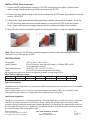
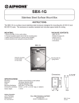
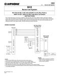
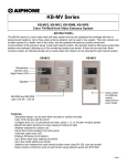
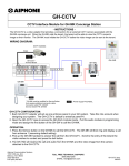
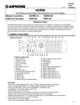
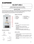
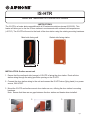
IS-HTR
Heater and Thermostat for IS Series Door Stations
-INSTRUCTIONSThe IS-HTR is a heater plate compatible with all IS series door stations (except IS-SS-2G). This
heater will allow you to use the IS door stations in environments with extreme cold temperatures
(-40°F/C). The IS-HTR will mount to the back of the door station using the existing mounting hardware.
Gasket side facing station
8-7/16”
Metal side facing wall
4-1/8”
INSTALLATION: Surface mount unit
1. Ensure that the conformal side (orange) of IS-HTR is facing the door station. Route all door
station wiring through the wiring provision opening on the IS-HTR.
2. Connect the door station wiring to the unit and connect the IS-HTR wires (flying leads) to a power
source, 24V AC/DC.
3. Mount the IS-HTR and surface mount door station as one, utilizing the door station’s mounting
hardware.
Note: Ensure that there are no gaps between the door station and heater when installed.
1.
2.
3.
Pg.1
INSTALLATION: Flush mount unit
1. Ensure that the conformal side (orange) of IS-HTR is facing the door station. Route all door
station wiring through the wiring provision opening on the IS-HTR.
2. Connect the door station wiring to the unit and connect the IS-HTR wires (flying leads) to a power
source, 24V AC/DC.
3. Remove the 4 nuts and washers holding the plastic chassis to the metal front panel. Place the
IS-HTR as shown and reuse the nuts and washers to secure the IS-HTR to the door station.
Note: Ensure that there are no gaps between the door station and heater when installed.
4. Mount the door station and heater together to the desired backbox using the supplied hardware.
1.
2.
3.
Note: When using the IS-HTR with IS series emergency stations, the external relay board wires
should not be run through the IS-HTR.
SPECIFICATIONS:
Temperature:
-40°F to 140°F (-40°C to 60°C)
Heater Element:
23.04Ω (Resistive, Non-Inductive Pattern). 25 Watts (REF) at 24V
Thermostatically controlled
Thermostat Activation:
On at 59°F (15°C), Off at 77°F (25°C)
Power:
24V AC/DC (Recommend Aiphone PS-2420UL)
Wiring distances (taking into account a maximum allowable voltage drop of 10%):
Wire/ Distance Reference table:
10AWG
11AWG
14AWG
16AWG
18AWG
22AWG
24V (25W)
1150’ 725’
455’
285’
180’
70’
Special Precautions:
Installation and servicing should only be done by qualified service personnel and conform to all local building
and electrical codes.
When a single power source is used for both the sub station and heater module, the sub station power
consumption must be taken into consideration when determining the wire gauge.
Application Suggestion:
Though not a requirement, it is recommended that a site-wide temperature controller be used in conjunction
with the main power source(s) for the heater(s) utilized. Ideally this would prevent unnecessary heater
activation during the summer months where heater operation is not necessary (but temperatures are below
the thermostat set point of 15ºC). Additionally, the reduced operation of the thermostat would also increase
the service lifespan of the heater module itself.
Aiphone Corporation
1700 130th AVE NE Bellevue, WA 98005
Ph: (800) 692-0200 Fax: (425) 455-0071
TOLL FREE TECHNICAL SUPPORT:
(800) 692-0200
E-MAIL: [email protected]
Pg. 2
IS-HTR Instr.
0512JD