1
User’s Guide
Agilent Technologies 8922M/S GSM Test Set
Agilent Part No. 08922-90211
Printed in UK
January 1998
© Copyright 1998, Agilent Technologies. All rights reserved. No part of this manual may be reproduced in any form
or by any means (including electronic storage and retrieval or translation into a foreign language) without prior agreement and written consent from Agilent Technologies Inc. as governed by United States and international copyright
laws.
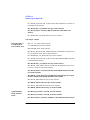
Contents
Declaration of Conformity.................................................................... v
Sales and Service Offices................................................................... viii
Agilent Technologies 8922M/S Documentation Description............... x
Typeface Conventions.......................................................................... xi
1 Installing Your Agilent 8922M/S
Using this Chapter ............................................................................. 1-2
Fuses and Power Cords ..................................................................... 1-3
Installation Overview ........................................................................ 1-5
General Information........................................................................... 1-8
2 Making Measurements
Using This Chapter ............................................................................ 2-2
Agilent Technologies 8922M/S Operating Modes ............................ 2-3
ACTIVE CELL.................................................................................. 2-5
TEST MODE ..................................................................................... 2-9
CW GENERATOR .......................................................................... 2-12
Measurements .................................................................................. 2-13
If You Have Problems with a Measurement ................................... 2-30
Advanced Features........................................................................... 2-39
3
Verifying Performance
About This Chapter............................................................................ 3-2
Setting up the Tests ............................................................................ 3-3
Getting the Right Equipment ............................................................ 3-4
Installing and Operating the Software .............................................. 3-5
Understanding the Tests..................................................................... 3-7
Understanding Test Failures ............................................................ 3-13
Agilent Technologies 8922M/S Specifications................................ 3-14
Contents-1
Contents
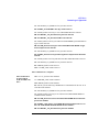
4 Screens
Field Types ........................................................................................ 4-2
Audio ................................................................................................ 4-4
Bit Error ............................................................................................ 4-8
Bit Error 2 ....................................................................................... 4-11
Cell Configuration - GSM 900 ....................................................... 4-16
Cell Configuration - E-GSM, DCS 1800, PCS 1900 ..................... 4-22
Cell Control - Active Cell ............................................................... 4-27
Cell Control - Active Cell + ........................................................... 4-31
Cell Control - Test Mode ................................................................ 4-33
Cell Control - CW Generator ......................................................... 4-35
Cell Control 2 ................................................................................. 4-37
Configure ........................................................................................ 4-49
CW Measurement ........................................................................... 4-54
Fast Bit Error .................................................................................. 4-56
I/O Configuration ........................................................................... 4-59
Logging .......................................................................................... 4-63
Measurement Sync ......................................................................... 4-64
Message .......................................................................................... 4-69
MS Information / Signaling ............................................................ 4-70
Oscilloscope, Main Controls .......................................................... 4-75
Oscilloscope, Trigger Controls ....................................................... 4-77
Oscilloscope, Marker Controls ....................................................... 4-80
Output RF Spectrum, Main View (Option 006 Only) .................... 4-82
Output RF Spectrum, Trace View (Option 006 Only) .................... 4-84
Phase and Frequency Error - Multiburst OFF ................................. 4-86
Phase and Frequency Error - Multi-burst ON ................................. 4-88
Phase/Freq, Phase Err ..................................................................... 4-91
Phase/Freq, Data Bits ..................................................................... 4-93
Pwr Ramp: Rise Edge .................................................................... 4-95
Pwr Ramp, Top 2 dB ...................................................................... 4-97
Contents-2
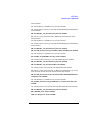
Contents
Pwr Ramp, Fall Edge ...................................................................... 4-99
Pwr Ramp: Summary .................................................................... 4-101
Pwr Ramp: Pulse (Option 006 Only) ............................................ 4-104
Pwr Ramp: Pulse Rise (Option 006 Only) .................................... 4-107
Pwr Ramp: Pulse Fall (Option 006 Only) ..................................... 4-109
RF Generator / RF Analyzer (AF Gen) ........................................ 4-111
RF Generator / RF Analyzer (RF Analyzer) ................................. 4-112
RF Generator / RF Analyzer (RF Gen) ......................................... 4-115
Service .......................................................................................... 4-118
SMS Cell Broadcast ...................................................................... 4-119
Spectrum Analyzer, Main Controls (Option 006 Only) ............... 4-122
Spectrum Analyzer, RF Gen Controls (Option 006 Only) ........... 4-124
Spectrum Analyzer, Marker Controls (Option 006 Only) ............ 4-125
Spectrum Analyzer, Auxiliary Controls ....................................... 4-127
Tests ............................................................................................... 4-129
5 Keys
Key Map ............................................................................................ 5-2
Function Keys .................................................................................... 5-3
Local Keys ...................................................................................... 5-10
Global Keys .................................................................................... 5-11
Units Keys ....................................................................................... 5-12
Contents-3
Contents
6 Connectors
Front-Panel Connectors of the Agilent Technologies 8922M/S ....... 6-2
Rear-Panel Connectors of the Agilent Technologies 8922M/S....... 6-10
Signal Descriptions for SYSTEM BUS ......................................... 6-18
Timing Diagrams............................................................................. 6-27
7 Messages
Communication Failures .................................................................. 7-2
Firmware Error ................................................................................. 7-3
Sync Status ....................................................................................... 7-4
Protocol Error Messages .................................................................. 7-5
Timers................................................................................................ 7-6
Disconnects ....................................................................................... 7-8
Protocol Log Examples Of Typical Calls........................................ 7-11
Monitoring For Protocol Failure And Recovery During Test. ........ 7-12
8 Instrument BASIC
Agilent Technologies 8922M/S Instrument BASIC Overview ......... 8-2
Configuration and Instrument Control .............................................. 8-4
Loading, Storing, and Running ....................................................... 8-10
Entering and Editing Programs ...................................................... 8-16
Memory Cards................................................................................. 8-20
Programming and Using the TESTS Subsystem............................. 8-26
Contents-4
Contents
A APPENDIX A
Purpose ............................................................................................. A-2
Equipment Required ......................................................................... A-3
Connecting the Agilent 8922M to the HP/Agilent 37900D ............. A-4
Setting Up the Agilent Technologies 8922M ................................... A-5
Setting Up the HP/Agilent 37900D .................................................. A-6
How to Obtain a Protocol Log.......................................................... A-8
Additional Information ................................................................... A-11
Protocol Log of a Typical Call........................................................ A-13
B Glossary
.......................................................................................................... B-2
Index 1
Contents-5
Contents
Contents-6
Warranty
Warranty
This Agilent Technologies instrument product is warranted against defects in material and
workmanship for a period of one year from date of shipment. During the warranty period,
Agilent Technologies will at its option, either repair or replace products which prove to be
defective.
For warranty service or repair, this product must be returned to a service facility
designated by Agilent Technologies. Buyer shall prepay shipping charges to Agilent
Technologies and Agilent Technologies shall pay shipping charges, duties, and taxes for
products returned to Agilent Technologies from another country.
Agilent Technologies warrants that its software and firmware designated by Agilent
Technologies for use with an instrument will execute its programming instructions when
properly installed on that instrument. Agilent Technologies does not warrant that the
operation of the instrument, or software, or firmware will be uninterrupted or error free.
Limitation of Warranty
The foregoing warranty shall not apply to defects resulting from improper or inadequate
maintenance by Buyer, Buyer-supplied software or interfacing, unauthorized modification
or misuse, operation outside of the environmental specifications for the product, or
improper site preparation or maintenance.
NO OTHER WARRANTY IS EXPRESSED OR IMPLIED. AGILENT
TECHNOLOGIES SPECIFICALLY DISCLAIMS THE IMPLIED WARRANTIES OF
MERCHANTABILITY AND FITNESS FOR A PARTICULAR PURPOSE.
Limitation of Remedies and Liability
THE REMEDIES PROVIDED HEREIN ARE BUYER’S SOLE AND EXCLUSIVE
REMEDIES. AGILENT TECHNOLOGIES SHALL NOT BE LIABLE FOR ANY
DIRECT, INDIRECT, SPECIAL, INCIDENTAL, OR CONSEQUENTIAL DAMAGES,
WHETHER BASED ON CONTRACT, TORT, OR ANY OTHER LEGAL THEORY.
i
Responsibilities of the Customer
Responsibilities of the Customer
The customer shall provide;
1
Access to the products during the specified periods of coverage to perform maintenance.
2
Adequate working space around the products for servicing by Agilent Technologies
personnel.
3
Access to and use of all information and facilities determined necessary by Agilent
Technologies to service and/or maintain the products. (In so far as these items may
contain proprietary or classified information, the customer shall assume full
responsibility for safeguarding and protection from wrongful use.)
4
Routine operator maintenance and cleaning as specified in the Agilent Technologies
Operating and Service Manuals.
5
Consumables such as paper, disks, magnetic tapes, ribbons, inks, pens, gases, solvents,
lamps, filters, fuses, seals, etc.
Certification
Agilent Technologies certifies that this product met its published specifications at the time
of shipment from the factory. Agilent Technologies further certifies that its calibration
measurements are traceable to the United States National Bureau of Standards and
Technology, to the extent allowed by the Bureau’s calibration facility, and to the
calibration facilities of other International Standards Organization members.
Assistance
Product maintenance agreements and other customer assistance agreements are available
for Agilent Technologies products.
For any assistance, contact your local Agilent Sales and Service Office. For a list of
contact information, see “Sales and Service Offices” on page ix.
ii
Notices
Notices
The material contained in this document is subject to change without notice. AGILENT
TECHNOLOGIES MAKES NO WARRANTY OF ANY KIND WITH REGARD TO
THIS MATERIAL, INCLUDING, BUT NOT LIMITED TO, THE IMPLIED
WARRANTIES OF MERCHANTABILITY AND FITNESS FOR A PARTICULAR
PURPOSE. Agilent Technologies inc. shall not be liable for errors contained herein or for
incidental or consequential damages in connection with the furnishing, performance or use
of this material.
Agilent Technologies assumes no responsibility for the use or reliability of its software on
equipment that is not furnished by Agilent Technologies.
Restricted Rights Legend
If Software is for use in the performance of a U.S. Government prime contract or
subcontract, Software is delivered and licensed as "Commercial computer software" as
defined in DFAR 252.227-7014 (June 1995), or as a "commercial item" as defined in FAR
2.101(a) or as "Restricted computer software" as defined in FAR 52.227-19 (June 1987) or
any equivalent agency regulation or contract clause. Use, duplication or disclosure of
Software is subject to Agilent Technologies’ standard commercial licenseterms, and nonDOD Departments and Agencies of the U.S. Government will receive no greater than
Restricted Rights as defined in FAR 52.227- 19(c)(1-2) (June 1987). U.S. Government
users will receive no greater than Limited Rights as defined in FAR 52.227-14 (June 1987)
or DFAR 252.227-7015 (b)(2) (November 1995), as applicable in any technical data.
Copyright 200X Agilent Technologies Inc. All Rights Reserved.
Statement of Compliance
This product conforms to EN61010-1(1993) / IEC 1010-1(1990) +A1(1992) +A2(1994) /
CSA C22.2 No. 1010.1(1993) Safety requirements for Electrical Equipment for
Measurement, Control and Laboratory Use, and has been supplied in a safe condition. The
instruction documentation contains information and warnings which must be followed by
the user to ensure safe operation and to maintain the instrument in a safe condition.
iii
Electromagnetic Compatibility (EMC) Information
Electromagnetic Compatibility (EMC) Information
This product has been designed to meet the protection requirements of the European
Communities Electromagnetic Compatibility (EMC) directive:
EN55011:1991 (Group 1, Class A)
EN50082-1:1992
- IEC 1000-4-2 (1995) ESD
- IEC 1000-4-3 (1995) Radiated Susceptibility
- IEC 1000-4-4 (1995) EFT
In order to preserve the EMC performance of this product, any cable which becomes worn
or damaged, must be replaced with the same type and specification.
Sound Emission
Manufacturer’s Declaration
This statement is provided to comply with the requirements of the German Sound
Emission Directive, from 18 January 1991.
This product has a sound pressure emission (at the operator position) < 70 dB(A).
❒ Sound Pressure Lp < 70 dB(A).
❒ At Operator Position.
❒ Normal Operation.
❒ According to ISO 7779:1988/EN 27779:1991 (Type Test).
Herstellerbescheinigung
Diese Information steht im Zusammenhang mit den Anforderungen der
Maschinenlärminformationsverordnung vom 18 Januar 1991.
❒ Schalldruckpegel Lp < 70 dB(A).
❒ Am Arbeitsplatz.
❒ Normaler Betrieb.
❒ Nach ISO 7779:1988/EN 27779:1991 (Typprfung).
iv
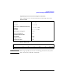
Declaration of Conformity
Declaration of Conformity
according to ISO/IEC Guide 22 and EN45014
Manufacturer’s Name:
Agilent Technologies.
Manufacturer’s Address:
Agilent Technologies
South Queensferry
West Lothian, EH30 9TG
Scotland, United Kingdom
Declares that the product
Product Name:
GSM MS Test Set
Model Numbers:
Agilent Technologies 8922M and 8922S
Product Options:
This declaration covers all options of the above products as detailed in
TCF A-5951-9852-02
Conforms with the protection requirements of European Council Directive 89/336/EEC on the approximation
of the laws of the member states relating to electromagnetic compatibility.
Against EMC test specifications EN 55011:1991 (Group 1, Class A) and EN 50082-1:1992
As Detailed in:
Electromagnetic Compatibility (EMC)
Technical Construction File (TCF) No. A-5951-9852-02
Assessed by:
Dti Appointed Competent Body
EMC Test Centre, GEC-Marconi Avionics Ltd.,
Maxwell Building, Donibristle Industrial Park,
KY11 5LB
Scotland, United Kingdom
Technical Report Number:6893/2200/CBR, dated 23 September 1997
Supplementary Information:
The product conforms to the following
safety standards:
EN 61010-1(1993) / IEC 1010-1(1990) +A1(1992) +A2(1994)
CSA-C22.2 No. 1010.1-93
EN 60825-1(1994) / IEC 825-1(1993)
The product herewith complies with the requirements of the Low Voltage Directive 73/23/EEC, and carries the CEmarking accordingly.
South Queensferry, Scotland
Location
17 November 1997
Date
R.M. Evans / Quality Manager
v
Safety Information
Safety Information
The following general safety precautions must be observed during all phases of operation
of this instrument. Failure to comply with these precautions or with specific warnings
elsewhere in this manual violates safety standards of design, manufacture, and intended
use of the instrument. Agilent Technologies Inc. assumes no liability for the customer’s
failure to comply with these requirements.
GENERAL
This product is a Safety Class 1 instrument (provided with a protective earth terminal).
The protective features of this product may be impaired if it is used in a manner not
specified in the operation instructions. All Light Emitting Diodes (LEDs) used in this
product are Class 1 LEDs as per IEC 60825-1.
ENVIRONMENTAL CONDITIONS
This instrument is intended for indoor use in an installation category II, pollution degree 2
environment. It is designed to operate at a maximum relative humidity of 95% and at
altitudes of up to 2000 meters. Refer to the specifications tables for the ac mains voltage
requirements and ambient operating temperature range.
BEFORE APPLYING POWER
Verify that the product is set to match the available line voltage, the correct fuse is
installed, and all safety precautions are taken. Note the instrument’s external markings
described under "Safety Symbols".
GROUND THE INSTRUMENT
To minimize shock hazard, the instrument chassis and cover must be connected to an
electrical protective earth ground. The instrument must be connected to the ac power
mains through a grounded power cable, with the ground wire firmly connected to an
electrical ground (safety ground) at the power outlet. Any interruption of the protective
(grounding) conductor or disconnection of the protective earth terminal will cause a
potential shock hazard that could result in personal injury.
FUSES
Only fuses with the required rated current, voltage, and specified type (normal blow, time
delay, etc.) should be used. Do not use repaired fuses or short-circuited fuse holders. To do
so could cause a shock or fire hazard.
vi
Safety Information
DO NOT OPERATE IN AN EXPLOSIVE ATMOSPHERE
Do not operate the instrument in the presence of flammable gases or fumes.
DO NOT REMOVE THE INSTRUMENT COVER
Operating personnel must not remove instrument covers. Component replacement and
internal adjustments must be made only by qualified service personnel.
Instruments that appear damaged or defective should be made inoperative and secured
against unintended operation until they can be repaired by qualified service personnel.
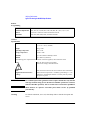
WARNING The WARNING sign denotes a hazard. It calls attention to a procedure,
practice, or the like, which, if not correctly performed or adhered to, could result in
personal injury. Do not proceed beyond a WARNING sign until the indicated conditions
are fully understood and met.
Caution
The CAUTION sign denotes a hazard. It calls attention to an operating
procedure, or the like, which, if not correctly performed or adhered to, could result in
damage to or destruction of part or all of the product. Do not proceed beyond a CAUTION
sign until the indicated conditions are fully understood and met.
vii
Safety Symbols
Safety Symbols
The following symbols on the instrument and in the manual indicate precautions which
must be taken to maintain safe operation of the instrument
Safety Symbols
The Instruction Documentation Symbol. The product is marked with this symbol when
it is necessary for the user to refer to the instructions in the supplied documentation.
Indicates the field wiring terminal that must be connected to earth ground before operating the equipment - protects against electrical shock in case of fault.
Frame or chassis ground terminal - typically connects to the equipment's metal frame.
Alternating current (AC)
Direct current (DC)
Warning, risk of electric shock.
N
Terminal for Neutral conductor on permanently installed equipment.
L
Terminal for Line conductor on permanently installed equipment..
The CE mark shows that the product complies with all relevant European Legal Directives.
ISM 1-A
This is a symbol of an Industrial, Scientific, and Medical Group 1 Class A product.
The CSA mark is a registered trademark of the Canadian Standards Association, and
indicates compliance to the standards defined by them.
Indicates that a laser is fitted. The user must refer to the manual for specific Warning or
Caution information to avoid personal injury or damage to the product.
viii
Sales and Service Offices
Sales and Service Offices
Any adjustment, maintenance, or repair of this product must
be performed by qualified personnel. Contact your customer
engineer through your local Agilent Technologies Service
Center. You can find a list of local service service
representatives on the web at:
http://www.agilent-tech.com/services/English/index.html
You can also contact one of the following centers and ask for
a test and measurement sales representative.
Asia Pacific:
Agilent Technologies
19/F, Cityplaza One, 1111 King’s Road,
Taikoo Shing, Hong Kong, SAR
(tel) (852) 2599 7889
(fax) (852) 2506 9233
Japan:
Agilent Technologies Japan Ltd.
Measurement Assistance Center
9-1, Takakura-Cho, Hachioji-Shi
Yokyo, 192-8510
(tel) (81) 426 56 7832
(fax) (81) 426 56 7840
Australia/New Zealand:
Agilent Technologies Australia Pty Ltd
347 Burwood Highway
Forest Hill, Victoria 3131
(tel) 1-800 629 485 (Australia)
(fax) (61 3) 9272 0749
(tel) 0 800 738 378 (New Zealand)
(fax) (64 4) 802 6881
ix
Sales and Service Offices
Canada
Agilent Technologies Canada Inc.
5150 Spectrum Way,
Mississauga, Ontario
L4W 5G1
(tel) 1 877 894 4414
Europe:
Agilent Technologies
Test & Measurement
European Marketing Organisation
P.O. Box 999
1180 AZ Amstelveen
The Netherlands
(tel) (31 20) 547 9999
Latin America:
Agilent Technologies
Latin American Region Headquarters
5200 Blue Lagoon Drive, Suite #950
Miami, Florida 33126
U.S.A.
(tel) (305) 267 4245
(fax) (305) 267 4286
United States:
Agilent Technologies
Test and Measurement Call Center
P.O. Box 4026
Englewood, CO 80155-4026
(tel) 1 800 452 488
In any correspondence or telephone conversations, refer to
the power sensor by its model number and full serial number.
With this information, the Agilent Technologies
representative can quickly determine whether your unit is still
within its warranty period.
x
Agilent Technologies 8922M/S Documentation Description
Agilent Technologies 8922M/S Documentation
Description
Documentation Shipped with Your GSM Test Set
Agilent 8922M/S GSM Test Set Quick Start Guide.
This guide gives a brief description on how to make each of the measurements required to
test a GSM mobile phone. More detailed descriptions are given in the Agilent 8922M/S
GSM Test Set User’s Guide.
Agilent 8922M/S GSM Test Set User’s Guide.
This guide contains information on how to set up the Agilent 8922M/S for making
measurements and verifying performance. It also contains more detailed information on
each of the screens, keys, and connectors, and how to use the IBASIC facilities available
on the Agilent 8922M/S.
Agilent 8922M/S GSM Test Set Performance Test Software.
This 3.5 inch floppy disk allows you to verify the performance of the Agilent 8922.
Instructions on how to use this are detailed in the Agilent 8922M/S GSM Test Set User’s
Guide.
Agilent 8922M/S GSM Test Set Programming Reference Guide.
This guide describes, in detail, each of the GPIB command sets for the Agilent 8922M/S.
Agilent 8922 Multi-Band Test System User’s Guide1.
This is a supplementary user’s guide that describes the additional features found with the
Multi-Band test system. The test system is used for testing and making measurements of
dual band mobiles.
1.
The user’s guide is only available with the HP 8922M/S Option 010.
xi
Typeface Conventions
Typeface Conventions
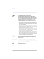
Italics
Italic type is used for emphasis.
Display
Display text is used to show examples, fields, and prompts that are
displayed on the Agilent 8922M/S screen.
PRESET
Keycaps on the Agilent 8922M/S keyboard are enclosed in boxes.
Soft keys
Display text is used to show examples, fields, and prompts that are
displayed on the Agilent 8922M/S screen.
Soft keys
All software listings in this manual can be identified with this font.
xii
1
Installing Your Agilent 8922M/S
1-1
Installing Your Agilent 8922M/S
Using this Chapter
Using this Chapter
Use the following procedure to get the Agilent Technologies 8922M/S powered-up
correctly. After completing this procedure, refer to the Quick Start Guide for an
introduction to operating the Agilent Technologies 8922M/S and Chapter 2,
“Making Measurements” for more extensive information on using the Agilent
Technologies 8922M/S.
Equipment Supplied •
•
•
Fuse Envelope and Fuse
REF OUT/REF IN cable (Option 001 only)
Power Cord
CAUTION
To avoid potential injury, ensure that two people are employed in lifting the Agilent
8922M/S out of the box and for any other instrument moves.
NOTE:
If you have the Agilent 8922M/S Option 010 Multi-Band Test System, refer to the
appropriate Agilent 8922 Multi-Band User’s Guide for more information on
connection and operating differences.
1-2
Installing Your Agilent 8922M/S
Fuses and Power Cords
Fuses and Power Cords
CAUTION
Before plugging this instrument into the Mains (line) voltage, be sure the correct
voltage on the line voltage selection card has been selected.
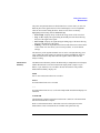
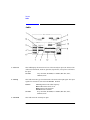
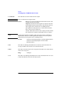
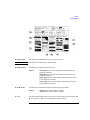
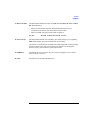
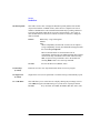
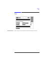
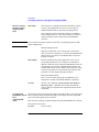
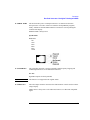
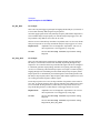
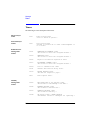
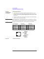
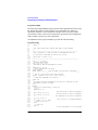
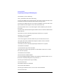
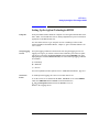
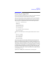
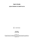
Line Voltage and
Fuse Selection
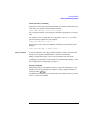
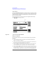
Verify that the line voltage selection card is matched to the power source
(see Figure 1-1 on page 1-3). Order fuse Agilent part 2110-0083 (2.5 A 250 V,
normal blow) for replacement.
Figure 1-1
Voltage Selection Card and Fuse Installation
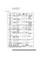
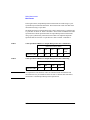
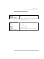
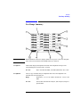
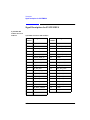
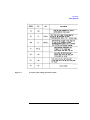
Other Fusing
Non user replaceable fusing on the secondary of this instrument power supply are;
Fuse
Current
Type
Volatge
F1
F2
F3
F4
F5
F6
5A
3A
10A
3A
0.5A
3A
F 5.0A H
F 3.0A H
F 10A
F 3.0A H
F 0.5A H
F 3.0A H
250V
250V
32V
250V
250V
250V
1-3
Installing Your Agilent 8922M/S
Fuses and Power Cords
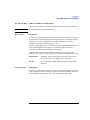
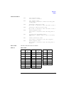
Power Cords
Agilent Part
Agilent
1-4
Installing Your Agilent 8922M/S
Installation Overview
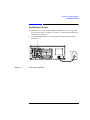
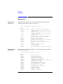
Installation Overview
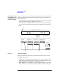
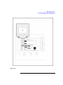
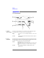
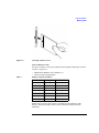
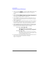
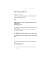
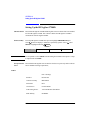
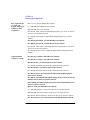
1
2
Connect a 1, 2, 5, 10, or 13 MHz signal to the REF IN. If you are using option
001, connect as shown, see Figure 1-2 on page 1-5, with the supplied cable (OPT
001 REF OUT to REF IN).
Connect the supplied power cord to the Agilent 8922M/S and power up the
instrument.
1
Power Source
Figure 1-2
Rear View Connections
1-5
Installing Your Agilent 8922M/S
Installation Overview
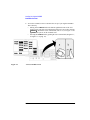
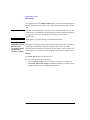
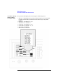
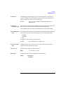
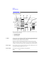
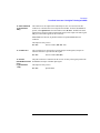
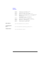
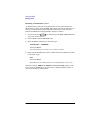
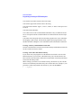
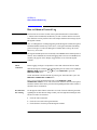
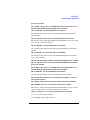
3
Figure 1-3
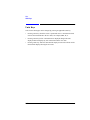
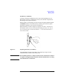
Access the CONFIG screen to customize the set-up of your Agilent 8922M/S.
This is done by:
• Moving to the CONFIG field in the bottom right-hand corner of the Cell
Control screen, (the first screen that appears after power-up or after selecting
PRESET ). Rotate the cursor control knob (refer to “a”, see Figure 1-3 on
page 1-6) until you are on the CONFIG field.
• Selecting the CONFIG field by pushing the cursor control knob (diagram “b”,
see Figure 1-3 on page 1-6).
Access CONFIG Screen
1-6
Installing Your Agilent 8922M/S
Installation Overview
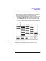
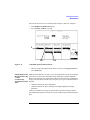
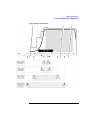
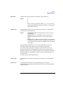
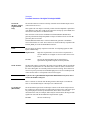
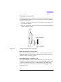
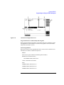
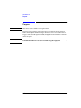
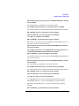
4
To guarantee the correct operation of the Agilent 8922M/S with all mobile
phones, you should use a high-stability timebase.
This step details how to configure the Agilent 8922M/S for use with either the
option 001, high-stability timebase, or an external reference signal.
A If you have option 001 installed and wish to use this as your reference, ensure
that the OPT 001 REF OUT field in the Configure screen is set to On.
Access the Reference field in the Configure screen and select 10 MHz.
B If you wish to use an external reference signal, set the Reference field to
1, 2, 5, 10, or 13 MHz according to the frequency reference you intend to use.
A
B
Figure 1-4
High-stability timebase set-up
To customize your Agilent 8922M/S further, refer to Chapter 4, Screens.
1-7
Installing Your Agilent 8922M/S
General Information
General Information
Operation and
Storage
Environment
Refer to General Specifications in the Agilent 8922M/S Specifications section of
Chapter 3, Performance Verification for information about the operation or storage
environment.
Instrument Options
Refer to Agilent 8922M/S Specifications in Chapter 3, Performance Verification for
information about instrument options.
Specifications
Refer to Agilent 8922M/S Specifications in Chapter 3, Performance Verification for
instrument specifications.
1-8
2
Making Measurements
2-1
Making Measurements
Using This Chapter
Using This Chapter
Use this chapter to obtain an overview of how to operate the Agilent 8922M/S GSM
Test Sets.
This chapter is divided into the following sections:
•
•
Making Measurements
• Agilent 8922M/S Operating Modes - explains how to configure the Agilent
8922M/S so that measurements can be made.
• Measurements - details how to perform the many different measurements
available on the Agilent 8922M/S.
Advanced Features - advanced information for experienced users.
To help you understand this chapter, you may wish to consult the following sources
of information:
•
•
•
•
NOTE:
Quick Start Guide - This briefly explains the basic operating principles of the
Agilent 8922M/S including making a call and simple measurements.
Typeface Conventions - Found at the front matter of this manual. This explains
how to interpret the different typefaces used in this manual.
Field Types - Refer to Chapter 4, Screens. Explains in detail the different kinds
of “fields” or areas which are displayed on the screens. Fields are mainly used for
measurement results, data entry and access to other screens.
Screens -Chapter 4, provides more detailed information on each of the fields
contained within all of the screens available on the Agilent 8922M/S.
If you have the Agilent 8922M/S Option 010 Multi-Band Test System, refer to the
appropriate Agilent 8922 Multi-Band User’s Guide for more information on making
dual band measurements.
2-2
Making Measurements
Agilent Technologies 8922M/S Operating Modes
Agilent Technologies 8922M/S Operating Modes
This section details the procedures necessary to control the Agilent 8922M/S and
GSM mobile phone in each of the main operating modes. It is recommended that
you read this section before attempting the “Measurements” section.
The Agilent 8922M/S GSM Test Sets have three main modes of operation, these are:
•
•
•
ACTIVE CELL
TEST MODE
CW GENERATOR
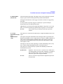
Active Cell
The first mode is the default mode and configures the Agilent 8922M/S as a GSM
Base Station emulator. This allows calls to be made from the Agilent 8922M/S to
the mobile phone and vice versa. Measurements can then be made to verify the
mobile phone’s performance.
Test Mode
This mode is used when measurements need to be made on the mobile phone
without a call being set up.
CW Generator
This mode configures the Agilent 8922M/S as a standard Continuous Wave (CW)
Signal Generator. This is used for test applications that require an unmodulated RF
carrier.
2-3
Making Measurements
Agilent Technologies 8922M/S Operating Modes
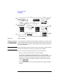
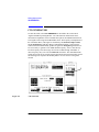
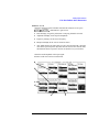
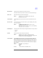
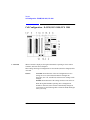
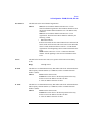
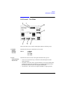
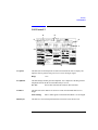
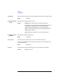
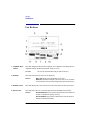
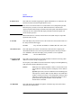
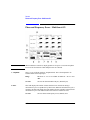
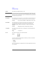
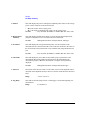
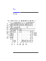
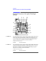
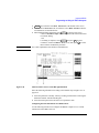
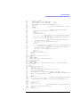
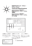
To configure the Agilent 8922M/S to the desired operating mode, carry out the
following instructions, referring to Figure 2-1 on page 4 for the position of the
fields.
•
NOTE
Ensure (1) is set to mobile phone type you require (GSM900, E-GSM, DCS1800,
or PCS1900).
For use with DCS1800 or PCS1900, refer to the HP/Agilent 83220A/E Users Guide
which explains how to configure the Agilent 8922M/S to test other mobile phone
formats.
•
•
Use the knob to move the cursor to the lower field below the Operating Mode (2).
Push the knob and select the desired Operating Mode (ACTIVE CELL, TEST
MODE, or CW GENERATOR) from the menu which appears at the bottom
right-hand side of the screen.
1
Figure 2-1
2
Agilent 8922M/S Operating Modes
In addition to the three main operating modes, there are three other modes available.
These are:
•
•
•
ACTIVE CELL+
TEST MODE+
CW GENERATOR+
These “+” modes have all the features of the other modes but include extra
diagnostic information on the screen. This information is designed to help advanced
users in fault-finding mobile phones.
2-4
Making Measurements
ACTIVE CELL
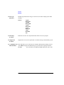
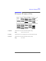
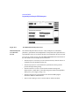
ACTIVE CELL
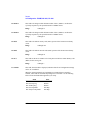
This is the default mode after cycling the power or selecting PRESET .
A functional mobile phone will lock on (camp on) to a signal which is produced by
the Agilent 8922M/S. The characteristic of this signal appears in the BASE
STATION fields, (1), see Figure 2-2 on page 2-6. These fields show the Channel
number and the Amplitude of the signal. Once the mobile phone has camped on to
the signal, it is possible to make a call between the mobile phone and the Agilent
8922M/S.
Making a Call From •
the Mobile Phone to •
the Agilent 8922M/S
•
•
•
Cycle the power on the Agilent 8922M/S or select PRESET .
Insert a Test SIM card into the mobile phone. [The Test SIM (Subscriber Identity
Module) holds the user’s customized information. Agilent supply both micro and
standard Test SIMs.]
Connect the mobile phone to the RF IN/OUT connector on the front panel of the
Agilent 8922M/S.
Switch on the mobile phone and wait for it to camp to the Agilent 8922M/S (most
mobile phones display 001-01 when the mobile phone has camped).
Dial any number on the mobile phone and press send.
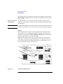
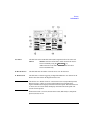
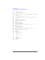
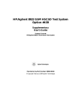
The call set-up should now proceed. The CALL STATUS field on the screen should
display CONNECTED, (2), see Figure 2-2 on page 2-6. Once the call has been
established, the following information is displayed:
•
•
•
Peak Power transmitted by the mobile phone is displayed in the center of the
screen.
In the CELL STATUS area, (3), see Figure 2-2 on page 2-6, the mobile phone
reports its:
• Transmit power level (TX Lev)
• Received level (RX Lev)
• Received signal quality (RX Qual)
Confirmation of the Traffic Channel and Timeslot is displayed to the left of the
mobile phone reports.
If the call does not proceed, there may be a problem with the mobile phone. Refer to
“Test Mode” in this chapter which explains how to configure the Agilent 8922M/S
to troubleshoot the mobile phone. When a call is connected, any speech received
from the mobile phone is echoed back by the Agilent 8922M/S, into the mobile
phone with a 0.5 second delay. This allows provisional checking of the mobile
phone’s audio sections by speaking into the mobile phone and listening for the echo
of your voice.
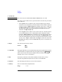
2-5
Making Measurements
ACTIVE CELL
3
2
3
4
6
5
Figure 2-2
Active Cell Mode
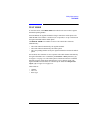
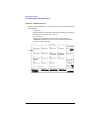
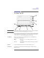
Making a Call From To call (or page) the mobile phone from the Agilent 8922M/S, it is necessary for the
the Agilent 8922M/S Agilent 8922M/S to know the number of the SIM in the mobile phone. [This number
to the Mobile Phone is the International Mobile Subscriber Identity (IMSI). This and other information is
stored on the SIM card.]
NOTE
The Network number cannot be used to make a call. The Network Telephone number
is allocated to the SIM and is used in a real network to page the IMSI.
There are two ways the Agilent 8922M/S can receive this information:
•
Make a call from the mobile phone to the Agilent 8922M/S.
Once the call is originated from the mobile phone, the Agilent 8922M/S
automatically reads the IMSI on the SIM card. If the previous call on the Agilent
8922M/S was made with the SIM card inserted in the mobile phone, and the
mobile phone is camped to the Agilent 8922M/S, the mobile can be called by
pressing
•
2-6
ORG CALL
.
Enter the MS Information screen and enter the IMSI into the Agilent 8922M/S
manually.
Making Measurements
ACTIVE CELL
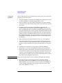
Press the following keys to do this:
•
•
•
SHIFT
, CELL CONFIG (MS INFO)
Move the cursor to the Paging IMSI field and enter the IMSI using the
numeric data entry keypad.
CELL CNTL , ORG CALL
Performing a “location update” from the MS INFO screen allows the Agilent
8922M/S to update the IMSI. This can be done by either:
•
changing the Current location parameters and waiting for the mobile phone to
re-camp.
•
setting IMSI Attach/Detach to On before powering on the phone. When the
phone camps its IMSI is set on the MS INFO screen and a call can be made from
the Agilent 8922M/S.
Changing Channel, Timeslot, and the Transmit Level
You can alter the parameters of the call before the call has been set up, or during a
call. They are displayed on the right-hand side of the screen under MOBILE
PHONE, (4), see Figure 2-2 on page 2-6. The parameters are:
•
•
•
Channel
Transmit Level (TX Level)
Timeslot
Channel To change channel, highlight the field and enter a new channel number
from the keypad. There is no interruption of communication between the Agilent
8922M/S and the mobile phone. For additional information on valid Absolute RF
Channel Numbers (ARFCNs), consult the specifications in Chapter 3.
TX Level This is a coded number used by the Agilent 8922M/S to command the
mobile phone to transmit at a particular power. When the TX Level is changed, two
things happen:
•
•
The mobile phone should change its transmitted power.
The Amplitude field in the Expected Input area of the screen, (5),
see Figure 2-2 on page 2-6, automatically adjusts to the nominal value defined by
the TX Level field. This allows the RF analyzer in the Agilent 8922M/S to
align itself with the mobile phone’s expected output amplitude. If the signal is not
within 3 dB of the expected amplitude, it is necessary to modify the Amplitude
field so that it is within 3 dB. Directly entering a value in the Amplitude field
does not change the transmitted level code transmitted to the mobile phone.
2-7
Making Measurements
ACTIVE CELL
There may be many reasons for the measured level not being close to the expected
level. The two most likely are that, either, the mobile phone is not operating
correctly, or, there is some power loss between the Agilent 8922M/S RF IN/OUT
connector and the mobile phone. If you suspect it is the second case, you can
compensate the Agilent 8922M/S generator settings and measurement results for
external losses or gains. The compensation is carried out in the CONFIGURE screen
which is accessed using the CONFIG field on the bottom right-hand side of the
screen, (6), see Figure 2-2 on page 2-6. Refer to Chapter 4, Screens for further
information.
Timeslot To change the timeslot, highlight the field and enter a new timeslot value
from the keypad. The timeslots can vary from 2 to 6. (Timeslots 0, 1, and 7 are
reserved for maintaining communication between the Agilent 8922M/S and the
mobile phone.)
NOTE
While the Active Cell is selected, the three MOBILE PHONE parameters are also
available on the bottom right-hand side of all measurement screens. This provides
control of the mobile phone during measurements.
2-8
Making Measurements
TEST MODE
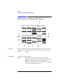
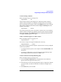
TEST MODE
To enter this mode, select TEST MODE as described in the section titled “Agilent
8922M/S Operating Modes”.
In TEST MODE, the Agilent 8922M/S no longer controls the mobile phone. The
TEST MODE is used when it is not desired, or not possible, to set up a call between
the Agilent 8922M/S and the mobile phone.
The MOBILE PHONE area available in Active Cell controls three functions
simultaneously:
•
•
•
The traffic channel transmitted by the Agilent 8922M/S.
The traffic channel transmitted by the mobile phone.
The corresponding channel used by the Agilent 8922M/S to measure the mobile
phone.
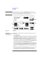
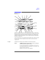
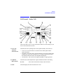
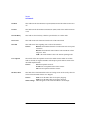
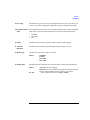
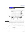
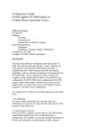
In Test Mode, these functions are now separated. The traffic channel transmitted by
the Agilent 8922M/S is now controlled by the Traffic Chan parameters, (1),
see Figure 2-3 on page 2-10. The mobile phone’s transmission must be controlled
manually using the mobile phone manufacturer’s service and test modes. The
Agilent 8922M/S measurements are controlled by the fields below Expected
Input, (2), see Figure 2-3 on page 2-10.
These fields are:
•
•
•
Channel
TX Level
Burst Type
2-9
Making Measurements
TEST MODE
NOTE
While the Test Mode is selected, the three MEASURE ON parameters are also
available on the bottom right-hand side of all measurement screens. This provides
control of the Expected Input parameters during measurements.
4
1
2
3
Figure 2-3
Test Mode
Mobile Phone
To measure an incoming signal from the mobile phone’s transmitter, perform the
Transmitter Testing following steps:
Using Test Mode
• Select TEST MODE.
• In the Expected Input area, (2), see Figure 2-3 on page 2-10, enter the GSM
channel number of the signal to be measured. This will automatically update the
input Frequency field below it, (3), see Figure 2-3 on page 2-10. If a
frequency needs to be measured which does not correspond to a standard GSM
channel, enter the non-standard value into the Frequency field. This value can
be anywhere from 10 MHz to 1000 MHz. A direct entry in the Frequency field
over-rides the frequency defined by the Channel field above.
• Enter the expected transmit level of the mobile phone in the TX Level field.
This will automatically update the Amplitude field below with the equivalent
TX level represented in dBm. If a non-standard input level is expected, enter the
value directly into the Amplitude field, this overrides the TX Level field
above.
• Enter the expected Colour Code of the input signal. The Colour Code is a function
of the central “midamble” of the transmitted burst and is needed so that
measurements are correctly synchronized to the received burst. If the Colour
2-10
Making Measurements
TEST MODE
Code is not known, it can be determined and corrected from measurements
described later. Refer to the “Advanced Features” section mentioned later in this
chapter.
NOTE
In the Active Cell mode, the Colour Code is automatically set.
Once these have been selected, the Agilent 8922M/S is ready to measure incoming
signals of the type specified. The mobile phone should be set up to generate a
corresponding test signal to the one expected. This will require access to the mobile
phone manufacturer’s servicing or test modes.
Mobile Phone
Receiver Testing
Using Test Mode
It is possible to analyze the mobile phone’s response to the Agilent 8922M/S
Broadcast Channel (BCH), by varying the BCH number and amplitude, (4),
see Figure 2-3 on page 2-10. TEST MODE provides the Agilent 8922M/S with a
“forced” traffic channel (TCH) generator which can be turned on and off without the
need for any signaling or the presence of a mobile phone. A forced TCH can be
generated on any channel in the GSM Base Station range and is enabled by the On/
Off toggle field (1) below the Traffic Chan or the ORG CALL and END CALL
keys.
The presence of both the BCH and forced TCH signals from the Agilent 8922M/S
allows the mobile phone’s receiver to be stimulated with signals identical to those
used on a real call. These signals can be used in conjunction with the mobile phone
manufacturer’s service and test modes to help measure and troubleshoot the mobile
phone. With these features, it is possible to make bit error rate measurements and
test the mobile phone’s receiver sensitivity when there is no call set up.
2-11
Making Measurements
CW GENERATOR
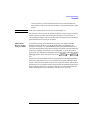
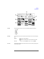
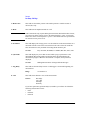
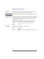
CW GENERATOR
To enter this mode, select CW GENERATOR as described in the section titled
“Agilent 8922M/S Operating Modes”. The CW Generator mode has the same
measurement capabilities as the Test Mode but replaces the GSM BCH and forced
TCH signals with a single unmodulated RF carrier. The frequency and amplitude of
the Continuous Wave (CW) signal is controlled by the Channel, Amplitude,
and the Frequency fields (1). When a GSM channel number is entered in the
Channel field, this automatically updates the generator Frequency field below it.
If it is necessary to generate a non GSM channel frequency, enter a value directly
into the frequency field. This range varies from 10 MHz through 1000 MHz. A
direct frequency entry over-rides the Channel field above. The unmodulated RF
signal can be used for any general purpose application and can be particularly useful
for checking some aspects of the mobile phone’s receiver where a CW signal is
needed.
1
Figure 2-4
CW Generator
2-12
Making Measurements
Measurements
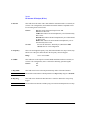
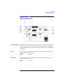
Measurements
The measurements available on the Agilent 8922M/S can all be accessed from the
cell control screen by selecting a measurement field under MEASUREMENTS,
(see Figure 2-5 on page 2-13) and pushing the knob.
GSM Specific
Measurements
The measurements available are:
Ancillary
Measurements
You can also use the toolkit capabilities of the Agilent 8922M/S. These additional
measurements are:
•
•
•
•
•
•
•
•
•
Peak Carrier Power
Phase and Frequency Error
Power Ramp Mask
Bit Error Rate
Output RF Spectrum (modulation or ramping, Option 006 only)
Spectrum Analyzer (Option 006 only)
Scope
Audio Measurements
CW Measurements
GSM Specific Measurements
Figure 2-5
Ancillary Measurements
Agilent 8922M/S Measurements
2-13
Making Measurements
Measurements
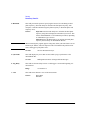
After making one type of measurement, another can be made by simply pressing
CELL CNTL and, using the knob, selecting the next measurement of your choice.
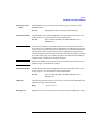
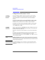
Peak Carrier Power The peak transmitter carrier power averages the transmitter carrier power for a
Measurement
single burst. This average is calculated over the time that the data information bits
are transmitted.
NOTE
Select the Pwr Zero field, disconnect external source and lower BCH power, (3),
see Figure 2-6 on page 2-14, to zero the power meter before any signal is applied.
Method
The peak transmitter carrier power value is displayed on the cell control screen.
After you have set up a call (Active Cell) or manually aligned the Agilent
8922M/S to the mobile phone (Test Mode/CW Generator), the Peak Power
reading is displayed in the center of the screen (1).
Below the CALL STATUS area of the cell control screen are reports from the
mobile phone. These appear only when using Active Cell. They indicate the TX
Level which the phone is transmitting and the RX Level and RX Quality of the
received signal, (2), see Figure 2-6 on page 2-14.
2
1
3
Figure 2-6
Peak Power Measurements
2-14
Making Measurements
Measurements
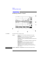
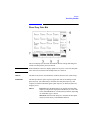
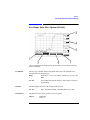
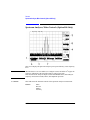
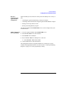
Phase and
Frequency Error
Measurement
Phase error and frequency error are measures of the modulation and noise
performance of the radio’s transmitter path.
Method
Select the PHASE FRQ field on the cell control screen to access the phase and
frequency measurements.
NOTE
The test is run automatically when the screen is selected.
The measurement fields in this screen are RMS Phase Error, Peak Phase Error and
Frequency Error (1), see Figure 2-7 on page 2-15.
The Agilent 8922M/S input sensitivity (2) can be varied, if necessary, to ensure that
the input signal level matches the Agilent 8922M/S RF Analyzer. Valid
measurements are only made when the signal is within 3 dB of the RF Analyzer
setting.
The Agilent 8922M has the option of using multi-burst measurements (4). This
gives the ability to make several phase and frequency measurements using more
than one burst. For more information refer to Chapter 4, Screens, Phase and
Frequency Error screen.
1
2
4
3
Figure 2-7
Phase and Frequency Error Measurements
Two additional screens in the phase and frequency measurement section can be
revealed if you select (3).
2-15
Making Measurements
Measurements
These are:
•
•
Power Ramp Mask
Measurements
PHASE ERR - this displays the phase error graphically. The phase error trace is
displayed using an autoscaling phase error axis versus data bits (numbered 0
through 147).
DATA BITS - this screen allows you display a screen which details the values
of the 148 bits in the timeslot (including midamble). If a known test signal is
being used, the reception of these bits can be verified.
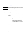
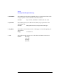
To avoid unwanted interference and to ensure successful reception at the Base
Station, the mobile phone’s transmitted signal must conform to GSM standards. The
purpose of the power ramp is to display the pulsed signal and verify that it conforms
to these standards.
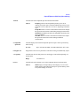
Method
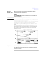
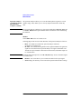
Selecting PWR RAMP on the cell control screen gives you access to the power ramp
measurement screens.
The marker (1), see Figure 2-8 on page 2-16 can be used to make a measurement at
a discrete point in time along the signal trace. The amplitude at this point is
displayed in the top left-hand corner of the screen.
2
Figure 2-8
1
Power Ramp Measurements
2-16
3
Making Measurements
Measurements
The power ramp measurements are divided into three screens where you can view
different parts of the signal and one screen which displays a series of amplitude
values at various times during the burst. These screens can be revealed by
highlighting and selecting from the View field (2):
•
•
•
•
Rise Edge - displays the top 30 dB of the rising section of the waveform.
Top 2 dB - displays the signal during the middle part of the burst allowing
analysis of the ripple of the signal.
Fall Edge - displays the signal during the falling edge of the burst allowing
analysis of the fall time of the signal.
Summary - details the amplitude measurements made at the times selected in the
12 time fields. You can choose your own time-positions, or use the default
settings.
The sensitivity of the Agilent 8922M/S receiver can be varied (3) allowing you to
verify whether the input signal level matches the Agilent 8922M/S RF Analyzer.
Valid measurements are only made when the signal is within 3 dB of the RF
Analyzer setting.
Measurement
Summary
The Measurement Summary field on the DSP Analyzer Ampl Main screen displays
whether HI/LO limits set for the measurement display fields, (Ampl1-12, pk+
flatness, or pk- flatness) were exceeded in the last measurement. The possible
Measurement Summary displays are:
Failed
One or more measurement limit was exceeded.
Passed
No measurement limits were exceeded.
---No measurement limits are set, or, all of the Ampl and Pk measurement displays are
turned off.
A blank field
The blank field is displayed when the measurement is armed. It will remain blank
until the measurement is complete.
Refer to “Pulse Measurements” within this section for a description of Pulse
Measurements. These measurements are available with option 006 only.
2-17
Making Measurements
Measurements
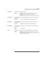
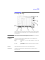
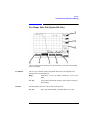
Pulse Measurements If you have option 006 (spectrum analyzer) installed, you can make measurements
(Available if Option on the lower portion of the pulse. These measurements can be accessed from the
006, Spectrum
Power Ramp screens.
Analyzer, is Fitted)
• The main measurements, Pulse On/Off Rise and Pulse On/Off Fall are displayed
at the top of the screen (1), see Figure 2-9 on page 2-18
• The sensitivity of the Agilent 8922M/S receiver can be varied (2) allowing you
to verify whether the signal still falls within the boundaries of the GSM power
mask.
1
3
Figure 2-9
2
Pulse Measurements
The Agilent 8922M/S provides three pulse measurements which can be selected
using View (3). These are:
•
•
•
Pulse - pulse on/off ratio measures the ratio of the average transmitter- power
(pulse on) to a specified time-position when power is reduced (pulse off). The
default settings are 28µs before bit 0 and 28µS after bit 147.
Puls Rise - this screen displays the signal during the initial rise of the pulse.
Puls Fall - this screen displays the signal during the final fall of the pulse.
2-18
Making Measurements
Measurements
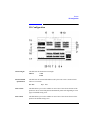
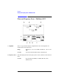
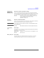
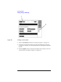
Bit Error Rate
Measurement
The Bit Error Rate measurement allows you to test the sensitivity of the mobile
phone’s receiver. By reducing the signal transmitted by the Agilent 8922M/S, you
can test the ability of the receiver to accurately decode its incoming signal. Data bits
that are decoded are sent back to the Agilent 8922M/S. The Agilent 8922M/S
compares them to original signal that was sent out and the differences are derived
from this. The audio echo function that works in the Cell Control screen is turned off
when making a BER measurement.
Method
To run a bit error rate test, select the BIT ERROR field in the cell control screen.
This reveals the bit error measurement screen.
This test will run automatically if you set the Single/Cont field to CONT. To run
a test set the Run/Stop field to RUN. This toggle field start/stops the BER test (1)
ratio, see Figure 2-10 on page 2-19.
NOTE
There are two sets of results displayed.
•
•
Intermediate Results - this is a running total of the bit errors as the bits are being
tested (2), (this is useful where a large number of bits are being tested).
Final Results - this shows the completed BER (3). This is displayed after all the
bits have been tested.
3
2
1
4
Figure 2-10
Bit Error Rate Measurement
2-19
Making Measurements
Measurements
By varying the Base station Amplitude field (4), you can test the mobile phone’s
receiver sensitivity. Actual results can be compared with the values reported by the
radio.
NOTE
If the Base Station amplitude is lowered too much, the radio will lose the call. This
will need to be re-established by increasing the base station amplitude, returning to
the cell control screen, and originating the call before you can continue
measurements.
NOTE
Not all phone types support burst-by-burst BER measurements.
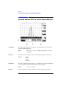
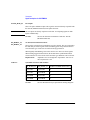
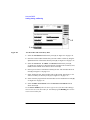
Output RF Spectrum
Measurements
(Available if Option
006, Spectrum
Analyzer, is Fitted)
The Output RF spectrum measurement shows the spectral power (due to the effects
of ramping or modulation) at a specified frequency offset. These are relative
measurements that compare the result at the offset frequency with the value at the
center frequency. You can also view the output RF spectrum trace from this screen.
Method
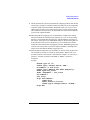
Select OUT RF SP in the cell control screen.
To make a measurement, do the following:
•
•
Ensure the Freq Offset is set to zero (1), see Figure 2-11 on page 2-21.
Select Ramp Ref or Mod Ref (2) (depending on whether you want to make a
ramping measurement or a modulation measurement).
2-20
Making Measurements
Measurements
This sets the reference level to which the offset frequency values are compared.
•
•
Select Ramping or Modulation (3).
Set your Freq Offset value (4).
5
2,3
Figure 2-11
Output RF Spectrum Measurements
•
Output RF Spectrum
Measurements Using
a 3-Pole
Synchronously
Tuned Measurement
Filter
1,4
The trace of the output RF spectrum can be viewed if you highlight View and
select Trace (5).
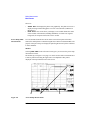
GSM Recommendation 11.10 and 11.20 set the requirements for the out-of-channel
performance of base station and mobile station transmitters with the Output RF
Spectrum specification. The specification calls for the measurement of transmitted
energy at several offsets from the carrier frequency. Two types of measurements are
required:
•
•
Check the interference due to modulation.
Check the interference due to ramping of the signal amplitude (switching
transients).
Limits are specified for each type of measurement at specified frequency offsets.
The GSM specified limits are based on a 5-pole synchronously tuned measurement
filter.
2-21
Making Measurements
Measurements
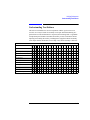
In the Agilent 8922, Output RF Spectrum measurements are made using a 3-pole
synchronously tuned measurement filter. The measurement results will differ from
measurements using a 5-pole filter.
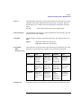
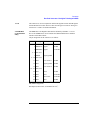
The difference between measurements of the “ideal” signals using a 3-pole filter and
a 5-pole filter are shown in Table 1 and Table 2. These values are added to the GSM
specifications to obtain equivalent limits for Output RF Spectrum measurements
using 3-pole synchronously tuned measurement filter. The adjusted Output RF
Spectrum limits are based on a 3-pole filter are shown in Table 3 and Table 4.
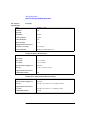
Table 1
3-Pole Specification Difference Output RF Spectrum due to Modulation
Offset from Carrier (kHZ)
Difference (dB)
Table 2
100
200
250
400
600 to
1800
0
2.5
1.0
9.0
0
3-Pole Specification Difference Output RF Spectrum due to Switching
Offset from Carrier (kHZ)
Difference (dB)
NOTE
400
600
1200
1800
6
4
2
0
It is important to note that these values are estimates based on simulation and
measurements. They are intended to allow the user to estimate their transmitters
conformance to GSM Output RF Spectrum requirements.
2-22
Making Measurements
Measurements
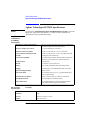
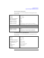
Table 3
Table 4
Adjusted Limits Based on 3-Pole Filter Output RF Spectrum Due to
Modulation
Power
Control
Level
Offset from Carrier (kHZ)
0
100
200
250
400
600 to
1800
0 (43 dBm)
0 dB
0.5 dB
-27.5 dB
-32 dB
-51 dB
-70 dB
0 (39 dBm)
0
0.5
-27.5
-32
-51
-66
0 (37 dBm)
0
0.5
-27.5
-32
-51
-64
≥5
(≤ 33 dBm)
0
0.5
-27.5
-32
-51
-60
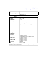
Adjusted Limits Based on 3-Pole Filter Output RF Spectrum Due to Switching
Power Level (dBm)
Offset from Carrier (kHZ)
400
600
1200
1800
43
-3 dB
-17 dB
-19 dB
-24 dB
41
-5
-17
-19
-24
39
-7
-17
-19
-24
37
-9
-17
-19
-24
35
-11
-17
-19
-24
33
-13
-17
-19
-24
31
-15
-19
-21
-26
29
-17
-21
-23
-28
27
-17
-22
-25
-30
25
-17
-22
-27
-32
23
-17
-22
-29
-34
≤ 21
-17
-22
-30
-36
2-23
Making Measurements
Measurements
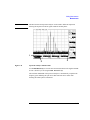
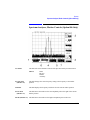
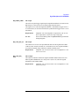
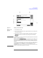
Spectrum Analyzer
(Available if Option
006, Spectrum
Analyzer, is Fitted)
The spectrum analyzer allows you to view the mobile phone’s signal over a wide
dynamic range. It also allows you to view any adjacent interference which may
exist.
NOTE
The spectrum analyzer can detect very low power signals where Active Cell and
even Test Mode cannot operate. Broken cable or connectors can be found using
this function.
Method
Select SPEC ANL in the cell control screen.
Selecting (1) provides access to other functions of the spectrum analyzer. These are:
•
•
NOTE
Main - the default screen has basic spectrum analyzer functions,
see Figure 2-12 on page 2-25.
RF Gen - this controls the RF generator in the Agilent 8922M/S. The generator
signal can be fed back into the spectrum analyzer for signal confirmation. The
Aux RF OUT port should be connected to the RF In/Out, and the RF Output set
to “Aux RF OUT”.
If both the input and output are set to RF IN/OUT, large errors in measured signal
level will be seen.
•
•
Marker - this screen allows you to control the marker for the input signal.
Auxiliary - the auxiliary screen controls the inputs and the attenuator settings.
2-24
Making Measurements
Measurements
NOTE
The RF Generator and spectrum analyzer can be tuned to different frequencies
allowing the inspection of the IF signals inside the mobile phone.
1
2
Figure 2-12
3
Spectrum Analyzer Measurement
Use the MeasReset (2) to reset the trace and measurements in the Agilent 8922M/
S. This is useful if you are using the Max Hold field (3).
The resolution bandwidth of the spectrum analyzer is automatically coupled to the
frequency span. Reducing the span to less than 200 kHz can be useful when
checking the mobile phone’s transmitter.
2-25
Making Measurements
Measurements
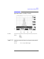
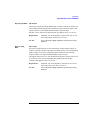
Scope
The oscilloscope function of the Agilent 8922M/S allows you to view the
demodulated signal from the mobile phone. This can be used for fault-finding in the
audio path.
Select SCOPE in the cell control screen to gain access to the oscilloscope function of
the Agilent 8922M/S.
Selecting (1), see Figure 2-13 on page 2-26, gives access to other functions of the
oscilloscope. These are:
•
•
•
Main - gives you the basic oscilloscope functions for viewing and measuring the
trace.
Trigger - allows you to trigger the input signal from a variety of sources.
Marker - offers you the capability to measure the voltage at discrete points in
time along the trace. The result is shown in the top right-hand corner of the
screen. You may find it helpful to use the SHIFT , PREV , (HOLD) feature
when using the marker.
2
3
1
Figure 2-13
Oscilloscope Measurements
Use the MeasReset (2) to reset the trace and measurements in the Agilent 8922M/
S. This is useful for single triggered measurements.
Set AF Anl In (3) to change the source of the signal being directed to the Audio
Analyzer Input. Refer to Screens, Chapter 4 for further information.
2-26
Making Measurements
Measurements
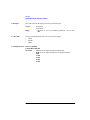
Audio
The audio function measures the audio frequency and voltage of the demodulated
signal from the mobile phone or from a number of other sources selectable using AF
Anl In (5), see Figure 2-14 on page 2-27.
Select AUDIO in the cell control screen to gain access to the audio function of the
Agilent 8922M/S.
The measurements of the audio voltage and frequency commence within a short
time of the screen being accessed.
The ac voltage (1) and the audio frequency (2) are the two main measurements made
in this screen. Additional measurements, such as DC Level, can be made by
selecting the AF Freq field. (2). The audio frequency generator (3) is used to
generate an audio signal from dc up to 25 kHz. The AF analyzer fields sets the
conditions for measuring the audio signal (4).
1
2
3
4
5
Figure 2-14
Audio Measurements
2-27
Making Measurements
Measurements
CW Measurement
The CW Measurement screen displays the carrier frequency and power of a
continuous (non-pulsed) signal. The CW Power measurement offers a greater
dynamic range than is available when making pulsed measurements.
CW Power is a broadband measurement. The CW Frequency measurement is
obtained using a tuned, selective input. The RF analyzer should be set to within 500
kHz of the expected signal frequency.
In the GSM band, the value that is entered should be set to the nearest 100 kHz.
Select CW MEAS in the cell control screen to gain access to the power measurements
of the Agilent 8922M/S.
The CW measurements are made automatically when you access the screen.
The CW Frequency field (1), see Figure 2-15 on page 2-28, displays the carrier
frequency of the signal and CW Power (2) shows the power of the carrier signal. It is
also possible to display the difference between the measured frequency and the
value selected by choosing CWFreqErr from field 1.
1
Figure 2-15
2
CW Measurements
These measurements can be reset using MeasReset. Select Pwr Zero before
power is applied to zero the power meter in the Agilent 8922M/S.
2-28
Making Measurements
Measurements
NOTE
Although CW Measurements is a broadband measurement, it uses calibration data
that relies on the expected input frequency being set correctly. The Power Detector
is connected so that it will only make measurements on signals present at the RF In/
Out port.
2-29
Making Measurements
If You Have Problems with a Measurement
If You Have Problems with a Measurement
This section tells you what to do if either of the following screen display events
occurs:
•
Message Line Messages (on the top of the screen).
•
•
•
Is a Message Line displayed at the top of the screen.
Possible Solutions to Message Line Errors.
Sync Status Messages
•
Is an Error Message Displayed in the Sync Status Field.
Refer to Chapter 7, “Messages”, for more information.
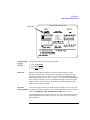
Is a Message Line
displayed at the top
of the screen?
At position 1, see Figure 2-16 on page 2-31, a message line appears if:
•
•
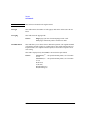
•
•
Attempt To Arm or Query an Inactive Measurement - check that a measurement
has been selected from the To Screen.
Trigger too late, decrease trigger delay - See Trigger Timing B
Trigger too early, increase trigger delay - See Trigger Timing B
Measurement Armed, awaiting trigger - See Trigger Timing A
2-30
Making Measurements
If You Have Problems with a Measurement
Figure 2-16
2-31
Making Measurements
If You Have Problems with a Measurement
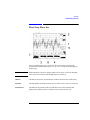
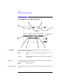
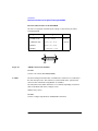
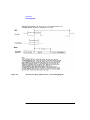
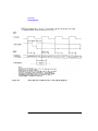
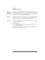
Possible Solutions to The signal processing hardware that is used to generate measurement results has to
Message Line Errors be told when to take data samples. If the trigger to do this is misaligned with the
signal, there may be errors in the results that are displayed.
Trigger Timing A
Check if the trigger is being received.
On the MEAS SYNC screen (press MEAS SYNC to gain access), check if the
correct burst type has been defined.
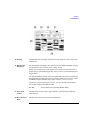
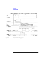
Trigger Timing B
Check if the trigger is being received at the correct time.
The First Bit field (A) , see Figure 2-17 on page 2-32, on the Phase Freq: Data
Bits screen displays the time difference between when a trigger is being received
and when the first bit of a burst occurred. The time difference is only valid if
FMErrCount is 0. The timing difference can be corrected by altering the trigger
delay (B).
A
B
Figure 2-17
2-32
Making Measurements
If You Have Problems with a Measurement
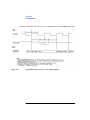
Trigger Range For Pulsed RF
2-33
Making Measurements
If You Have Problems with a Measurement
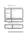
Is an Error Message The sync status field displays an error message for the following errors:
Displayed in the
• Bad Sync - demodulation error, perform a Phase/Frequency error measurement
Sync Status field?
to identify which of the Sync Status error listed below may be the possible
problem.
• FM Errors - see solutions 1, 2, 3, 4
• Short Burst - see solutions 1, 4
• Level Late - see solutions 1, 2, 3, 4
• Level Short - see solutions 1, 2, 3, 4
• Low Level- see solution 3
• RF Ovrload - see solution 3
2-34
Making Measurements
If You Have Problems with a Measurement
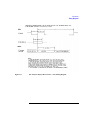
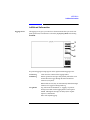
Possible Solutions to Solution 1 - Trigger Timing
Sync Status Errors
Check if the trigger is being received.
On the MEAS SYNC screen (press MEAS SYNC to gain access), check if the
correct burst type has been defined. On the Data Bits screen:
A The First Bit field on the Phase Freq:Data Bits screen displays the time
difference between when a trigger is being received and when the first bit of
a burst occurred (A). The time difference is only valid if FMErrCount is 0.
B Check the delay in the Trig Delay field (B).
A
B
Figure 2-18
2-35
Making Measurements
If You Have Problems with a Measurement
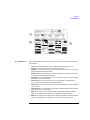
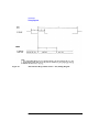
Solution 2 - Midamble Sync
On the MEAS SYNC screen (press MEAS SYNC to gain access),
• Check the definition of the signal’s burst type (A).
• Check the Burst Sel field (B).
A
B
Check the bit pattern of your measurement
Perform a Data Bits measurement (D). An “M” will display under the
bits that are identified as the midamble bits.
D
2-36
Making Measurements
If You Have Problems with a Measurement
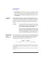
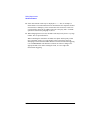
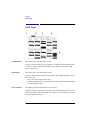
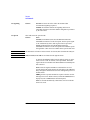
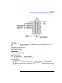
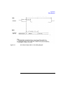
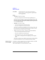
Solution 3 - Level
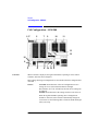
Check the following fields on the RF Generator/RF Analyzer screen (press
SHIFT , CELL CNTL , (RFG/RFA) to gain access).
3
Pulse field (a), (if signal is pulsed) Ext or Hop Trig should be selected.
4
Amplitude field (b), for the expected amplitude
5
Frequency field (c), for the correct frequency.
6
RF Input field (d), for the correct connector choice.
7
AGC Mode field (e). If either Open or Auto is the selected mode, check the
value in the Open Loop DAC (f) Value field. If Closed is the selected mode,
check that the burst is repetitive (at least one timeslot every two frames).
Check the actual amplitude of the input signal.
Perform a Peak Carrier Power measurement.
a
b
c
d
e
f
2-37
Making Measurements
If You Have Problems with a Measurement
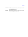
Solution 4 - Amplitude Envelope
•
Check if the Pulse Amplitude is ± 1 dB of the expected value during the useful
part of the burst.
If FM Errors:
Perform a Phase Freq:Data Bits measurement. Dashes (a) will display
under the bits where the power is too low.
If No FM Errors:
Perform pulse demodulation measurements. Connect PULSE
(DEMODULATION OUT) connector to SCOPE IN (MEASURE)
connector on the front panel.
a
2-38
---------
Making Measurements
Advanced Features
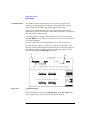
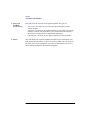
Advanced Features
Other Screens
The screens mentioned in this section are not necessary for simple measurement of
mobile phones as the work is done by the functions mentioned previously. However,
the advanced user may find it worthwhile to know what these screens are and what
they are capable of doing.
•
RF Generator/RF Analyzer - this screen controls the Agilent 8922M/S RF
generator and RF analyzer. This screen can be accessed by pressing the following
keys:
•
•
,
CELL CNTL
, (RFG/RFA)
MS Information - the MS INFO (Mobile Subscriber Information) screen gives
you access to the information about the mobile phone itself. A Location Update
can be verified from this screen. This screen can be accessed by pressing:
•
•
SHIFT
SHIFT
,
CELL CONFIG
, (MS INFO)
Cell Configuration - the CELL CONFIG screen gives you access to the control
parameters for the configuration of the cell. This screen can be accessed by
pressing:
•
CELL CONFIG
•
Cell Control 2 - gives you the capability to control the additional cell parameters.
This screen is relevant in the set up of a call. This screen can be accessed by
highlighting the More field in any main screen and selecting CELL CNTL2.
•
Hopping - the hopping screen allows you manual control of the hopping
frequencies. This feature is only available in the Agilent 8922G compatibility
mode.
•
Logging - the logging screen allows control over the Protocol Interface port on
the rear panel (option 003). To access this screen, highlight More and select
LOGGING.
•
Configuration - the configuration screen is a full instrument control screen
which allows you to set up the Agilent 8922M/S. Screen set up, compatibility
mode, radio type as well as other miscellaneous pieces of information are
contained on this screen. To access this screen, highlight More and select
CONFIG.
•
I/O Configuration - the I/O configuration screen allows you to set up the general
interface of the instrument, such as printer options. This screen can be accessed
by highlighting the More field in any main screen and selecting I/O CONFIG.
2-39
Making Measurements
Advanced Features
•
Using RF Rise
Triggering
SMS Cell Broadcast - the SMS CB screen allows you to test whether the mobile
phone is capable of correctly receiving and displaying a message sent from a base
station using the Short Message Service (SMS) Cell Broadcast protocol. This
screen can be accessed by highlighting the More field in any main screen and
selecting SMS CB.
When using RF Rise triggering of measurements, the Trigger Delay should be
adjusted so that the wanted data is captured during the sampling process. The actual
measurement is made at the Trigger Delay time after the RF Rise. When changing
from RF Rise triggering to another trigger mode, the Trigger Delay should be
adjusted to the appropriate value as the default Trigger Delay is not automatically
restored.
Example:
In the Agilent 8922M/S, when using the RF Rise, a Trigger Delay of 0 is recommended. When changing from RF
Rise to Ext Demod trigger mode, the default value of
473.4T should be re-entered for Trigger Delay.
The value 473.4T is derived from the 468.75 bits of delay
between downlink and uplink plus the 4.7 bits of modulation delay inside the Agilent 8922M/S. All timing is referenced to the beginning of bit zero on the downlink TCH
timeslot, (DCH or BCCH timeslot if TCH is not active.)
Effect of the RF
Generator on RF
Analyzer
Measurements
When the RF Generator is set to a high level relative to the analyzer RF input, some
error may be introduced in the analyzer’s power detector. This is due to the isolation
limits between generator and analyzer on the RF IN/OUT port. This only occurs
when the RF Generator and RF Analyzer share the RF IN/OUT port. If the
RF Generator uses the AUX RF OUT port, no error occurs.
RFgen + 14
RFin – 20
----------------------------- ------------------------
10
10
+ 10
Error = 10LOG 10
– ( RFin – 20 ) dBm
RFin is the amplitude in dBm of the signal into the RF IN/OUT port. Normally the
setting in dBm of the RF Analyzer Amplitude. RFgen is the setting in dBm of the
RF Generator.
Because the two components are not always in phase, the actual error will often be
slightly less.
2-40
Making Measurements
Advanced Features
Power Ramp Setting The mobile transmitter output ramp should settle so that it complies with the power
Time
mask (GSM Rec 11.10) by the time output level calibration is done in the
manufacturing process. The power mask is displayed in the Power Ramp screens.
Peak Carrier Power measurement method is not made to GSM Rec. 11.10. If you
need to make a measurement to this specification, go to the Power Ramp Summary
screen. The field in the top right-hand corner displays the Peak Carrier Power to
GSM Rec. 11.10. Refer to PWR RAMP: SUMMARY screen (item 5) for a
description.
Peak Carrier Power The algorithm for the Peak Carrier Power measurement is based on the use of a fast
Measurement,
sampler taking continuous asynchronous measurements of the power detected at the
Assumptions And
RF IN/OUT port.
Algorithm
The sampler accumulates 75µS sample bins containing the maximum power
observed during the period and the minimum power observed during the period.
Sampling rate is 10 MHz. The maximum and minimum values observed are based
on 750 individual samples within the period.
A trigger is provided at the middle of bit 0 of the burst. (When using RF Rise
triggering, the actual trigger may occur several bits earlier due to the ramp up of the
burst.) In response to this trigger, the following 6 sample bins (0 - 5) from the
sampler are saved and reported to the measurement processor.
Timeslot
0µS
577µS
Mobile Burst
Amplitude
Trigger
Sample
Bins
-2
-1
0
1
2
3
4
5
6
7
8
9
375µS Window
75µS/sample_bin
2-41
Making Measurements
Advanced Features
The beginning of the 0 sample bin will be between 0 and 75µS (bit 0 - 20) after the
trigger as the sampler runs asynchronously to the trigger. The last sample bin will
complete sampling between 450µS and 525µS (bit 121 - 142) into the burst.
The measurement processor discards the 0 sample bin. This effectively removes the
ramp-up overshoot. Each measurement is also RF Power Qualified to ensure only
valid bursts are measured. Measurements with a result below the qualification level
are discarded.
The remaining sample bins 1-5 are averaged for the displayed measurement result.
Each measurement is therefore based on a 375µS (102 bit) sampling of the burst.
A mobile which does not meet the amplitude mask and has erratic amplitude across
the burst could give erroneous results with this measurement algorithm. It is
therefore essential that mobiles first comply with the amplitude mask in
GSM Rec. 11.10.
Making
There are two ways of making a synchronized external measurement using triggers
Synchronized
from the Agilent 8922M/S:
External
Measurements Using 1 Use the G_EXT_TRIG on the rear panel SYSTEM_BUS connector. See
Chapter 6, Connectors for a pin out diagram.
Triggers From The
Agilent 8922M/S
This is a separate trigger directly from the Protocol Processor. It is only
selectable from the SERVICE screen. Once set it will provide continuous
triggers on each frame. Caution must be used as this trigger can have up to a
0.75 bit error due to the 156/157 bit variance in timeslots.
(GSM Recommendations allow use of 156/157 bit timeslots instead of the
156.25 bit length.)
To use the G_EXT_TRIG signal:
Go to the CONFIG screen.
Select the SERVICE field on the right hand side of the screen.
Select the LATCH field and find the selection labeled:
‘g_ext_trig_enable’ (SERV:LATCH:SEL ‘g_ext_trig_enable’)
Enter a ‘1’ in the VALUE field. (SERV:LATCH:VAL 1)
Select the LATCH field and find the selection labeled:
‘g_ext_trig’ (SERV:LATCH:SEL ‘g_ext_trig’)
Enter the TIMESLOT and BITPOSITION on which you want the
trigger to occur.
Example:
2-42
432 hex is TIMESLOT=4 BITPOSITION=32 hex. The
maximum TIMESLOT=7 and the maximum BITPOSITION=9C hex (Bit 0 - 157).
Making Measurements
Advanced Features
NOTE
The GPIB requires the use of base 10 values, 432h = 1074d, for example:
SERV:LATCH:VAL 1074.
2
The value entered is relative to the beginning of the zero bit of the zero
slot on the downlink baseband.
A 4.7 bit modulator delay occurs between the baseband and the RF
domain which must also be taken into account. Since the value may
only be integer, round to the nearest whole value.
The following timing error is introduced due to 156/157 bit timing.
Timeslot=0,4 No Error
Timeslot=1,5 +.75 bit error (early trigger)
Timeslot=2,6 +.50 bit error
Timeslot=3,7 +.25 bit error
Use MEAS_TRIG_OUT on the rear panel SYSTEM_BUS connector.
This is the delayed trigger from the Measurement System. In the normal
ACTIVATED operation, the Protocol Processor sends triggers to the
Measurement System on the zero bit of each downlink TCH burst. The
Measurement System applies the ‘Meas Trig’ ‘Trigger Delay’ to this input and
then, after the elapsed time, begins making its measurement. After this elapsed
time, the Measurement System also sends a trigger transition to the
MEAS_TRIG_OUT signal on the rear panel SYSTEM_BUS connector.
The trigger is only generated when a measurement is being made. This signal
may be used to trigger an externally connected measurement device such as the
HP/Agilent 71150/250 GSM high performance spectrum analyzers.
2-43
Making Measurements
Advanced Features
Unexpected
Operations
NOTE
These are descriptions of operations which may be unclear to the user as to how they
occurred. These are NOT defects.
1
The Agilent 8922M/S occasionally sends ABORTS to the attached protocol monitor. These ABORTS are normal and logging data is not lost.
2
In the FA and SD/4+FA control channel configurations, the Agilent 8922M/S
sends speech frames rather than fill frames on the FACCH when there is nothing
else to send.
3
The DRX ON mode corresponds to the NORMAL paging mode. The
Agilent 8922M/S sends continuous paging mode NORMAL on the idle PCH
blocks. The DRX OFF mode corresponds to the REORGANIZE paging mode.
The Agilent 8922M/S sends continuous paging mode REORGANIZE on the idle
PCH blocks. When in the REORGANIZE paging mode, the Agilent 8922M/S is
guaranteed to page on a random PCH block which is not the block expected in
the NORMAL paging mode. The active PCH block will page the MS with the
paging mode set to SAME. The SAME mode means “the same paging mode as
last indicated.”
4
TMSI reallocation in the Agilent 8922M/S uses the two (2) octet TMSI size.
5
The Agilent 8922M/S does not turn off the transmitter during DTX when the
voice activity detector (VAD) determines that there is no speech input present.
Instead, the Agilent 8922M/S sends a silence descriptor (SID) on every speech
frame.
6
USE MEM is not intended to be used with Pulse (Pulse ON/OFF Ratio)
measurements - do not select USE MEM after making a pulse measurement.
7
During a Pulse (Pulse ON/OFF Ratio) measurement the following message can
occur if the device under test is generating a larger signal than is expected: ‘RF
Overpower occurred during Pulse On/Off Ratio measurement’. This message
cannot be queried via GPIB. Use the Hardware 1 Status Register Bit 5 to detect
this condition when doing pulse measurements.
Option 006 (spectrum analyzer) must be installed to make pulse measurements.
8
The Output RF Spectrum measurement and Pulse On/Off Rise and Fall
measurement results shown on the Main view screens are not accessible via
GPIB or IBASIC. These measurement results are available on the Trace view
screens. All GPIB and IBASIC actions with these fields refer to those fields
shown on the Trace view screens.
2-44
Making Measurements
Advanced Features
9
The RF Generator may become uncalibrated in a hopping situation when the last
CW frequency setting was outside the GSM or DCS band. If you are using the RF
Generator outside the normal GSM or DCS bands, make sure you set a valid
GSM or DCS frequency in the CW frequency before entering a hopping mode.
This includes the ACTIVE CELL (ACTIVATED state on the CELL CONFIG 2
screen) on the Agilent 8922M/S.
10 When using RF Rise triggering it is recommended to set MS_Parms:Timing
Advance to MANUAL with the Timing Advance set to zero. If AUTO timing
advance is used with RF Rise triggering, the Agilent 8922M/S, operating as a
base station, will progressively command the mobile to advance timing until it is
at the maximum value of 64. It is difficult to recover from this state without
ending the call with the mobile. Changing back to EXT_DEMOD triggering will
cause the call to drop. This is because the Agilent 8922M/S is listening for the
mobile 64 bits later than the RF Rise triggering left it.
11 When making measurements over the GPIB, it is often necessary to place timeout constraints in software to account for mobile failure. When a time-out is
encountered while a measurement is armed but not complete, it is necessary to
perform a “CLEAR” operation on the GPIB. A “RESET” operation is
insufficient.
Example
ASSIGN @gpib TO 714
OUTPUT @gpib;”TRIGger:ASTate ’ARM’”
ON TIMEOUT 7,5 GOTO Flag1
OUTPUT @gpib;”MEASure:DSP:PHASe:FREQuency?”
ENTER @gpib;The_answer
PRINT ‘FREQUENCY:’; The_answer
OFF TIMEOUT 7
GOTO Flag2
Flag1:OFF TIMEOUT 7
CLEAR @gpib
PRINT “Timeout Occurred”
OUTPUT @gpib;”TRIGger:ASTate ‘DISARM’”
Flag2:END
2-45
Making Measurements
Advanced Features
12 Some measurement results may be displayed as ---- due, for example, to
mobile failure. The measurement has been armed but has not completed. In these
circumstances a GPIB query of the measurement will not return a result. This
event should be catered for by adding a time-out to the query and a “CLEAR”
operation as described in paragraph 11, above.
13 When changing between screens, the DSP results may briefly show a very large
number. This is expected behavior.
When controlling the instrument via GPIB, some phase and frequency results
may consistently return a very large number. This is most likely caused by
attempting to read result from another DSP screen when measurement triggering
is set to Continuous. The alternative solutions are either to change to the
appropriate DSP screen before reading the result, or to use single-shot
measurement triggering.
2-46
Making Measurements
Advanced Features
2-47
3
Verifying Performance
3-1
Verifying Performance
About This Chapter
About This Chapter
The tests in this chapter verify the electrical performance of the Agilent 8922M/S
GSM Test Set using the Agilent 8922 Performance Test Software provided with the
product. If the instrument passes this verification, its operation and specifications are
assured within the measurement uncertainties provided in the performance test print
out. Because of the specialized nature of the Agilent 8922M/S and the equipment
required to support it, it is recommended that calibration and repair be performed
only by specially equipped Agilent Technologies service centers.
A list of specifications is found at the end of this chapter.
3-2
Verifying Performance
Setting up the Tests
Setting up the Tests
This chapter contains the following information:
Getting the Right
Test Equipment
Required Test Equipment lists the test equipment needed for the performance
tests. This is the only equipment supported by the Agilent 8922 Performance Test
Software and is required to verify instrument operation. Equipment substitutions or
manual performance tests are not recommended or supported by Agilent
Technologies.
Installing and
Operating the
Software
Performance Test Software describes how to install and operate the Agilent 8922
Performance Tests software.
3-3
Verifying Performance
Getting the Right Equipment
Getting the Right Equipment
The following equipment is required to do all of the performance tests. The test
descriptions have an equipment list that specifies the equipment used for each
particular test.
Equipment
3-4
HP/Agilent Model Number
Measuring Receiver
8902A
Sensor Module
11722A
Audio Analyzer
8903B
Voltmeter
3456A
Signal Generator
8657A/B Opt. 022
Multifunction Synthesizer
8904A Opt. 001/002
Pulse Generator
8116A
Spectrum Analyzer
8566B
Technical Computer with Rocky Mountain
BASIC and DS Disk Drive
HP9000 Series 200/300
GPIB/RS-232 printer
HP 2225A
Verifying Performance
Installing and Operating the Software
Installing and Operating the Software
Performance Test Software is supplied on a 3.5-inch, double-sided floppy disk and
is written to run with BASIC 5.0 and later. Modifications to the program should be
limited to changing the default addresses and storing copies for back-up purposes.
Understanding the
Tests
Test Descriptions contains a description of each test that is performed by the
Performance Test software. This description is intended to help locate problems if
the software fails to execute properly or to help users understand the test
methodology that is used in each performance test. The descriptions are not step by
step procedures for manual performance tests.
To Load the
Program.
To verify the performance of the Agilent 8922M, you need to convert the instrument
back from an Agilent 8922G, or convert the Agilent 8922S to an Agilent 8922E. To
do this refer to the following section titled “Using the Compatibility Switch - Back
Conversion”.
You are now ready to run the Performance Test Software.
1
Put the disk in the disk drive.
2
Type LOAD “PT_8922”, press
ENTER
.
After you have completed the Performance Tests, return the instrument back to the
Agilent 8922M or Agilent 8922S by following the instructions in the following
section titled “Using the Compatibility Switch - Forward Conversion”.
Using the
Compatibility
Switch
Back Conversion
To turn the instrument from the Agilent 8922M/S back to an Agilent 8922G or an
Agilent 8922E, select the following keys:
•
•
•
•
CONFIG (this is accessible from the Cell Control screen in the bottom right-hand
corner).
Compatible, select 8922G or 8922E
HP-IB Adrs (22)
PRESET
The instrument is now set up as an Agilent 8922G or Agilent 8922E and ready for
Performance Verification testing.
3-5
Verifying Performance
Installing and Operating the Software
Forward Conversion
To return the instrument from an Agilent 8922G back to an Agilent 8922M or an
Agilent 8922E to an Agilent 8922S, select the following keys:
•
•
•
•
More (this is accessible from the Cell Control screen in the bottom right-hand
corner). Scroll down the list and select CONFIG.
Compatible, select 8922M or 8922S
HP-IB Adrs (14)
PRESET
The instrument is returned to an Agilent 8922M or Agilent 8922S.
To Configure the
GPIB Addresses
ENTER
1
With the program loaded, type EDIT DEFAULT_ADDRESS, press
2
Modify each line to indicate the proper instrument address (700-730).
.
It is now possible to re-store the program as “PT_8922” or store it under a
different name.
To Run the Program 1 Type RUN, press
2
ENTER
.
Follow the directions as they appear on the screen.
Notes on Running the Program.
The first screen which appears is the GPIB status of each piece of test equipment
that is supported. It is only necessary to have the instruments responding that will be
used in each particular test. Make certain that each instrument you will be using is
responding at the proper address. Duplicate addresses may make an instrument
appear to be responding but this is not allowed. Press “I” (for Ignore) to continue
past this screen.
The second screen prompts you for the instrument model. If you have disk
08922-10006, select HP 8922G (for Agilent 8922M performance testing) or HP
8922E (for Agilent 8922S performance testing). The third screen which will appear
is the main Performance Tests selection menu. Three options are available on this
screen:
•
Select the performance test to run, remember the test instruments and UUT must
be responding over GPIB.
•
Turn the printer function ON or OFF. If the printer function is turned on it must
be responding over GPIB or the program will lock up.
•
Exit from the program.
Press the key corresponding to the option that you would like to perform. The other
screens that appear are connection instructions, error messages and output results.
3-6
Verifying Performance
Understanding the Tests
Understanding the Tests
This section describes the theory of each performance test, lists the equipment
needed for the test, and provides some problem solving information.
Test 01: Signal
Generator Level
Equipment Required
Measuring Receiver HP/Agilent 8902A
Sensor Module HP/Agilent 11722A
Theory of the Test
The UUT is set to generate CW signals at various levels and frequencies. The HP/
Agilent 8902A/11722A is used as a power meter to measure high level signals and
the HP/Agilent 8902A tuned RF level function is used to measure low level signals.
Things To Check In Case Of Problems
•
The HP/Agilent 8902A/11722A must be calibrated and zeroed for accurate
measurement results. The HP/Agilent 11722A calibration factors must be entered
into the HP/Agilent 8902A.
•
Low level signals from the Agilent 8922M/S must be very stable to be measured
by the tuned RF level function of the HP/Agilent 8902A. The instrument
timebases should be locked together. Also, if the Agilent 8922 source has
unusually high residual FM it may cause the low level measurements to fail
because the HP/Agilent 8902A cannot lock onto the signal.
•
Mismatch uncertainty causes a high level of uncertainty in this measurement.
3-7
Verifying Performance
Understanding the Tests
Test 02: Signal
Generator Spectral
Purity
Equipment Required
HP/Agilent 8566B Spectrum Analyzer
Theory of the Test
The UUT is set to generate a CW signal at various levels and frequencies. The HP/
Agilent 8566B is used to measure the signal level and then the level of the
harmonics or spurious signals.
Things To Check In Case Of Problems
•
The instruments should have their timebases locked together to assure that the
frequency offsets for the spurious measurements are accurate.
Test 03: Signal Pulse Equipment Required (excluding Agilent 8922M/S)
Modulation
HP/Agilent 8116APulse Generator
Theory of the Test
The HP/Agilent 8116A pulse generator drives the pulse input of the UUT and
causes it to generate pulsed RF signals. These signals are detected with the negative
diode detector and analyzed with the oscilloscope. The UUT is set to generate two
different on/off ratios: 30 dB and 80 to 90 dB. Rise time and fall time for each of
these is measured.
When the Agilent 8922S is the UUT, the RF Generator is set to generate a pulsed
GMSK signal. This signal is then analyzed with the UUT detector and oscilloscope.
Things To Check In Case Of Problems
•
The oscilloscope is used to automatically measure rise and fall times. If the RF
signal has high video feedthrough, it may cause the oscilloscope to make a faulty
reading by triggering on the video feedthrough instead of the actual pulse.
•
A diode detector with a greatly different sensitivity may cause the demodulated
waveform to overrange on the oscilloscope or have reduced accuracy because of
the resolution of the oscilloscope.
3-8
Verifying Performance
Understanding the Tests
Test 04: Signal
Generator 0.3
GMSK Modulation
Equipment Required (excluding Agilent 8922S)
HP/Agilent 8904A Option 001/002 Multifunction Synthesizer
Theory of the Test
The HP/Agilent 8904A is used to generate a 270.833 kHz clock and random data.
This drives the UUT RF generator to generate the 0.3 GMSK modulated signals
with random data. This signal is then analyzed by the UUT to assure that the
frequency and phase errors are correct.
If the UUT is an Agilent 8922S, clock and data signals are generated internally, and
the HP/Agilent 8904A is not used.
Things To Check In Case Of Problems
Test 05: Audio
Frequency
Generator
•
This test should only be performed if the UUT analyzer is known to be accurate.
Run test #9 first if there is any question about the accuracy of the UUT analyzer.
•
Even when the accuracy of the UUT analyzer is known, its specification is such
that this test still has a high degree of measurement uncertainty.
•
A possibility to verify an instrument that fails this test may be to use a second
Agilent 8922M/S to analyze the signal or use the HP/Agilent 11836A 0.3 GMSK
measurement software. This software (and its associated hardware) has a lower
measurement uncertainty but is not currently supported with the Agilent 8922
Performance Tests software.
Equipment Required
HP/Agilent 3456AVoltmeter
HP/Agilent 8903BAudio Analyzer
HP/Agilent 8902AMeasuring Receiver
Theory of the Test
The UUT is set to generate audio signals at various levels and frequencies. The
voltmeter measures AC and DC level accuracy, the audio analyzer measures residual
distortion, and the measuring receiver measures frequency accuracy.
Things To Check In Case Of Problems
•
The measuring receiver and the UUT should have their timebases locked to make
accurate frequency measurements.
3-9
Verifying Performance
Understanding the Tests
Test 06: Audio
Equipment Required
Frequency Analyzer
HP/Agilent 8904A Option 001/002Multifunction Synthesizer
HP/Agilent 3456AVoltmeter
Theory of the Test
The HP/Agilent 8904A is used to generate accurate test signals which are analyzed
by the UUT. The voltmeter is used to reduce measurement uncertainty by accurately
characterizing the test signal level to predict the correct response of the UUT. The
voltmeter is used in the AC level, DC level, SINAD and distortion measurements.
Distortion test signals are generated by summing two sinewaves in the HP/Agilent
8904A, one as the desired signal, the other as a distortion product.
Things To Check In Case Of Problems
•
For frequency accuracy measurements the HP/Agilent 8904A timebase should be
locked to the UUT.
•
The voltmeter reading is used as a reference to normalize the reading from the
UUT. The output “measured” result is the actual reading from the UUT
normalized by the actual reading from the voltmeter. If the voltmeter makes a
faulty reading, it will normalize the actual UUT response and cause it to appear
faulty also. If the front panel reading from the UUT is significantly different from
the printed “measured” response, the normalization may be the cause.
Test 07: Oscilloscope Equipment Required
HP/Agilent 8903BAudio Analyzer
HP/Agilent 3456AVoltmeter
Theory of the Test
The audio analyzer is used to generate CW reference signals which are
characterized by the voltmeter and fed into the UUT. The voltmeter reading is used
to normalize the reading from the UUT oscilloscope. The oscilloscope
measurements are taken using the UUT marker function which is set to the peak of
the input sinewave.
Things To Check In Case Of Problems
•
The voltmeter reading is used as a reference to normalize the reading from the
UUT. The output “measured” result is the actual reading from the UUT
normalized by the actual reading from the voltmeter. If the voltmeter makes a
faulty reading, it will normalize the actual UUT response and cause it to appear
3-10
Verifying Performance
Understanding the Tests
faulty also. If the front panel reading from the UUT is significantly different from
the printed “measured” response, the normalization may be the cause. If the
oscilloscope triggers incorrectly, the peak search may not find the actual peak
response on the display.
Test 08: RF Analyzer Equipment Required
Level
HP/Agilent 8657A/B Signal Generator
HP/Agilent 8902A Measuring Receiver
HP/Agilent 11722A Sensor Module
Theory of the Test
The signal generator is used to generate CW signals at various frequencies and
power levels. These are accurately characterized by the HP/Agilent 8902A/11722A
and used as a reference. The CW signals are then used to test the UUT which is
compared to the reference reading taken by the HP/Agilent 8902A/11722A.
Things To Check In Case Of Problems
•
Mismatch uncertainties cause a high level of measurement uncertainty in this
measurement. If the HP/Agilent 11722A or HP/Agilent 8657A/B has a high
SWR, the accuracy of the results may be reduced.
Test 09: RF Analyzer Equipment Required
GMSK Modulation
HP/Agilent 8116APulse Generator
HP/Agilent 8904A Opt. 001/002Multifunction Synthesizer
HP/Agilent 8657A/B Option 022.Signal Generator
Theory of the Test
The HP/Agilent 8904A frequency modulates the GMSK signal generator with a
known amount of phase error. This test signal is used to verify the UUT’s ability to
measure this known signal. The actual measurements are compared to the predicted
to determine the accuracy of the UUT. The HP/Agilent 8904A is also used to create
the 270.833 kHz clock signal and the pulse generator is used to create a random data
pattern. Polarity of the data signal from the HP/Agilent 8657A/B Option 022 is not
important in this measurement.
Things To Check In Case Of Problems
•
Make certain the option 022 part of the 8657A/B is locked up to the 270.833 kHz
3-11
Verifying Performance
Understanding the Tests
clock signal. The option does not have GPIB control so the program cannot verify
that the option is operational.
Test A: RF Analyzer Equipment Required
Pulse Demodulation
HP/Agilent 8657A/B Signal Generator
HP/Agilent 8116A Pulse Generator
Theory of the Test
The Pulse generator drives the signal generator to generate Pulsed RF signals at
various frequencies. The UUT demodulates these signals and the internal
oscilloscope measures the rise and fall time of the demodulated waveform. This test
verifies the demodulator rise and fall time specifications.
Things To Check In Case Of Problems
•
Test B: Spectrum
Analyzer (Option
006 only)
The oscilloscope measurement functions are used to measure the 10% to 90% rise
and fall time. If the demodulated waveform has significant video feedthrough or
the oscilloscope cannot trigger the measurements properly, an incorrect
measurement may result.
Equipment Required
HP/Agilent 8657A/B Signal Generator
Theory of the Test
The signal generator is used to stimulate the UUT spectrum analyzer at various
frequencies. At each frequency, the spectrum analyzer is tuned to measure its own
image and spurious responses. The level of the signal generator is set to various
levels to determine the spectrum analyzer’s log-linearity.
Things To Check In Case Of Problems
•
The absolute accuracy of the signal generator causes a significant measurement
uncertainty in the log linearity measurements. A more accurate measurement is
to reduce the signal level using a precision attenuator. This is an acceptable
secondary manual test if the UUT fails the automated test.
3-12
Verifying Performance
Understanding Test Failures
Understanding Test Failures
This section is intended to be used in conjunction with the Agilent 8922 Series
Assembly Level Repair Guide for assembly level repair and troubleshooting. If a
performance test fails and hardware is suspected, the following table is a guideline
to help identify the hardware assemblies most likely to cause each failure. Before
replacing an assembly, the memory card diagnostics (supplied with the Assembly
Level Repair Guide) should also be run to help verify which assembly is defective.
ASSEMBLIES TESTED (P=Primary S=Secondary)
Performance Test
A2 A3 A4 A5 A6 A9 A1 A12 A13 A14 A15 A16 A17 A18 A19 A23 A24 A25 A26 A27
1
Sig Gen Level
S
S
P
S
P
S
S
S
S
Sig Gen Spectral Purity
S
S
S
S
S
S
S
S
S
Sig Gen Pulse Mod
S
P
S
P
S
S
S
S
S
S
Sig Gen .3 GMSK
P
S
S
S
S
S
S
S
S
P
AF Generator
S
S
AF Analyzer
P P
S
Oscilloscope
S
S
RF Analyzer Power
RF Analyzer GMSK Mod
S
P
S
P
S
RF Analyzer Pulse Demod
S
P
S
Spectrum Analyzer
S
S
S
P
S
S
P
S
3-13
Verifying Performance
Agilent Technologies 8922M/S Specifications
Agilent Technologies 8922M/S Specifications
NOTE:
If you have the Agilent 8922M/S Option 010 Multi-Band Test System, refer to the
appropriate Agilent 8922 Multi-Band User’s Guide for more information on
specifications relevant to dual band testing.
GSM900 and
E-GSM900
Functionality
Bit/Frame Error Rate Measurements:
Class 1a, 1b, and Class II bits in both raw and residual form.
Also Burst-by-Burst Bit Error Measurement
MS Power Output Level Control:
0 to 19 with RF analyzer auto adjust
Broadcast Channel Capability:
BCCH + CCCH or BCCH + CCCH + SDCCH/4
Control Channels (SDCCH, FACCH,
SACCH)
BCCH + CCCH, BCCH + CCCH + SDCCH/4, SDCCH/8
(non-hopped), SACCH/FACCH
Call Control Capabilities
BS originated call (FS/EFS), MS originated call (FS/EFS),
MS camp on, BS call disconnect, MS call disconnect
Traffic Channels
TCH (FS/EFS)
HSCSD
2x1 and 2x2, 9.6 kbs and 14.4 kbs
Timing
Auto, manual, uplink-downlink, offset measurement
Hopping
Two independent, user definable MA tables with offsets
Speech Encoding/Decoding
Full rate speech
Speech Echo Mode
User selectable delay 0 to 5 sec on Agilent 8922M, fixed
delay on Agilent 8922S
Measurement Coordination
Flexible control of burst type, ARFCN, and timeslot.
SACCH MEAS Result
RXLEV, RXQUAL, and timing advance.
SMS Cell Broadcast
Two predefined messages with user definable attributes
(code, update number, language and identifier).
RF Generator
Specifications
Frequency
Range
10 MHz to 1 GHz
Resolution
1 Hz
Accuracy
Reference accuracy ± 0.5 Hz
Stability
Same as reference
3-14
Verifying Performance
Agilent Technologies 8922M/S Specifications
Supplemental Characteristics:
Frequency Overrange
To 1015 MHz with uncalibrated output and modulation
Switching Speed
577 µs over the GSM frequency bands in hop mode (refer to 0.3
GMSK modulation specs
Output
RF In/Out Connector
−14 to −127 dBm
Level Range
Level Resolution
Level Accuracy
0.1 dB
2
GSM Bands1
50 MHz to 1 GHz
10 MHz to 50 MHz
Reverse Power
SWR
Aux RF Out Connector
Level Range
Level Resolution
±1.0 dB, levels ≥−127dBm,
maximum over range > −12 dB ±1.0 dB,
typically for levels ≥−127 dBm while hopping.
±1.5 dB, levels ≥−107 dBm
±2.0 dB, levels ≥−127 dBm
±2.0 dB, levels ≥−107 dBm
±2.5 dB, levels ≥−127 dBm
15 Watts continuous
100 Watts for 10 seconds/minute
1.5:1
+4 to −127 dBm
0.1 dB
Level Accuracy2
GSM Bands1
50 MHz to 1 GHz
10 MHz to 50 MHz
±1.0 dB, levels ≥−107 dBm
±1.0 dB, typically for levels≥−107 dBm while hopping.
±1.5 dB, levels ≥−107 dBm
±2.0 dB, levels ≥−127 dBm
±2.0 dB, levels ≥−107 dBm
±2.5 dB, levels ≥−127 dBm
Reverse Power
200 milliwatts
SWR
2.0:1, level <−4 dBm
1. GSM frequency bands are 880 to 915 MHz and 925 to 960 Mhz.
2. Level accuracy degrades 0.2 dB when using the RF in/out connector for both RF generator and RF analyzer. In 30dB
pulse mode, level accuracy specifications are typical.
3-15
Verifying Performance
Agilent Technologies 8922M/S Specifications
Spectral Purity
Spurious Signals (for ≤+1 dBm output level at Aux RF Out or ≤−19 dBm output level at RF In/Out.
Harmonics:
<−25 dBc
Non-harmonics:
<−50 dBc, >5 kHz offset from carrier
0.3 GMSK Modulation
After one timeslot, 577µs, from an isolated RF Generator Trigger in the GSM
Frequency bands.
Phase Error
≤1° rms
Peak Phase Error
≤4° peak
Frequency Error
± [0.02 ppm (18 Hz) + reference accuracy], for normal bursts
Typically ±[0.03 ppm (27 Hz) + reference accuracy], for RACHs.
Amplitude Flatness
±0.25 dB peak.
Clock Input (Agilent 8922M only)
Frequency
270.833 kHz ± 2 Hz (relative to reference).
Level
TTL
Data Input (Agilent 8922M only)
Format
Non differentially encoded input.
Level
TTL
Supplemental Characteristics:
After three timeslots, 1.73 ms, from an isolated RF Generator Trigger in the GSM frequency bands
Phase Error
≤0.5° rms
Peak Phase Error
≤2.0° peak
Frequency Error
±[0.01ppm (9 Hz) + reference accuracy] for normal bursts.
±[0.02ppm (18 Hz) + reference accuracy] for RACH bursts.
Pulse Modulation
Input Levels (Agilent 8922M only)
Rise/Fall Time (10% to 90%)
TTL
≤5 µs
Supplemental Characteristics:
>80 dB
On/Off Ratio
3-16
Verifying Performance
Agilent Technologies 8922M/S Specifications
30 dB Pulse Modulation (Agilent 8922M only)
All timeslots 30 dB higher than desired/active timeslot, to test adjacent timeslot
rejection.
Supplemental Characteristics:
Input Levels
TTL
Rise/Fall Time (10 to 90%)
≤5 µs
AM for Level Control (Agilent 8922M Only)
For output levels ≤+1 dBm at Aux RF Out or ≤−19 dBm at RF In/Out
Supplemental Characteristics:
Input
Range
−1.0V to +0.6V
Impedance
600Ω nominal, DC Coupled
Sensitivity
100% AM per volt, nominal
Calibration
0 VDC input produces calibrated output from the RF Generator
Rise/Fall Time (10 to 90%)
≤10 µs
3-17
Verifying Performance
Agilent Technologies 8922M/S Specifications
RF Analyzer
Specifications
Frequency
Range
10 MHz to 1 GHz
Resolution
1 Hz
Hop Mode
Resolution
100 kHz
Offset Frequency
≤50 kHz
Offset Resolution
1 Hz
RF In/Out SWR
<1.5:1
Supplemental Characteristics:
Frequency Overrange
To 1015 MHz
Offset Resolution
500 Hz for FM demodulation out
CW RF Frequency Measurement
Range
10 MHz to 1 GHz
Level Range
RF In/Out
−6 to +41 dBm
Aux RF In
−36 to +20 dBm
Input Frequency Setting Error
±500 kHz
Accuracy
±(1 Hz + reference accuracy)
Supplemental Characteristics:
Minimum Resolution
1 Hz
CW RF Power Measurements (RF In/Out Only)
Range
-5 to +41 dBm
Input Frequency Setting Error
±500 kHz
Accuracy
±0.5 dB ± noise effects (+4 to +41 dBm) (0.2 mW)
Supplemental Characteristics:
Accuracy
±0.5 dB ± noise effects (-5 to +4 dBm) (0.2 mW)
Minimum Resolution
0.01 dB
3-18
Verifying Performance
Agilent Technologies 8922M/S Specifications
Peak/Transmitter Carrier Power Measurement
RF In/Out only. After one timeslot, 577 µs, from an isolated Receiver Hop Trigger
in the GSM bands.
Range
-5 to +41 dBm
Input Frequency Setting Error
±10 kHz
Input Level Setting Error
±3 dB
Accuracy
±0.6 dB ± noise effects (+4 to +41 dBm) (0.2 mW)
Supplemental Characteristics:
Accuracy
±0.6 dB ± noise effects (-5 to +4 dBm) (0.2 mW)
Minimum Resolution
0.2 dB
Power Measurement Accuracy
Accuracy (dB)
0.5
0.4
0.3
0.2
0.1
0
-5
0
5
10
15
20
25
30
35
Power (dBm)
Pulse ON/OFF Ratio Measurement (Requires Option 006)
ON power is averaged over the useful part of the burst. OFF is averaged over a one
bit interval centered at a user specified time. Non-hopped mode only.
Input Frequency Setting Error
±10 kHz
Input Level Setting Error
±3 dB
Timing Accuracy
±1.7 µs (± 1.1 µs typical)
3-19
Verifying Performance
Agilent Technologies 8922M/S Specifications
Accuracy (ON/OFF 40 dB, RF In/Out only)
OFF Power (dBm)
ON/OFF Ratio Accuracy
−30 to −1
±2.4 dB
±1.1 typically
−37 to −30
±2.9 dB
±1.3 typically
−42 to −37
±3.7 dB
±1.7 typically
−47 to −42
±4.2 dB
±2.1 typically
Amplitude Envelope Measurement
After one timeslot, 577µs, from an isolated Receiver Hop Trigger in the GSM
Frequency bands
Measurement Range
RF In/Out
−6 to +41 dBm
Aux RF In
−36 to 20 dBm
Input Frequency Setting Error
±10 kHz
Inaccuracy due to Noise (for overshoots ≤ 1 dB):
Relative
Input Level Setting Error
±1 dB
±3 dB
±3 dB w/5 averages
0 dB
<±0.15 dB pk
<±0.2 dB pk
<±0.2 dB pk
−6 dB
<±0.2 dB
<±0.3 dB
<±0.3 dB
−30 dB
<+3.0 dB
<+4.2 dB
<+2.2 dB
−3.8 dB
−7.5 dB
−2.6 dB
Level
3-20
Verifying Performance
Agilent Technologies 8922M/S Specifications
Phase and Frequency Measurements
After one timeslot, 577µs, from an isolated Receiver Hop Trigger in the GSM
Frequency bands.
Range
RF In/Out
−6 to +41 dBm
Aux RF In
−36 to +20 dBm
Input Frequency Setting Error
±10 kHz
Input Level Setting Error
±3 dB
RMS phase error accuracy
≤1° rms
Peak phase error accuracy
≤4° peak
Frequency error accuracy
±[0.02 ppm (18 Hz) + reference accuracy], for normal bursts.
Typically ±[0.03ppm (27 Hz) + reference accuracy] for RACH bursts.
Supplemental Characteristics
After three timeslots, 1.73 ms, from an isolated Receiver Hop Triggering the GSM frequency band.
RMS phase error accuracy
≤0.5° rms
Peak phase error accuracy
≤2° peak
Frequency error accuracy
±[0.01 ppm (9 Hz) + reference accuracy], for normal bursts.
±[0.02 ppm (18 Hz) + reference accuracy] for RACH bursts.
0.3 GMSK Data Recovery (Agilent 8922M only)
After one timeslot, 577µs, from an isolated Receiver Hop Trigger in the GSM
Frequency bands
Range
RF In/Out
−6 to +41 dBm
Aux RF In
−36 to +20 dBm
Input Frequency Setting Error
±100 Hz
Required Input Phase Accuracy
≤5° rms, ≤20° peak
Demodulation Duty Cycle
1 timeslot per frame
Outputs
Data, Clock and Data Valid
Data Output Clock
Clocked at 1 MHz rate
Delay, data
≤1 frame (4.62 ms).
Output Level
TTL
3-21
Verifying Performance
Agilent Technologies 8922M/S Specifications
FM Demodulation Output (Agilent 8922M only)
Range
RF In/Out
−6 to +41 dBm
Aux RF In
−36 to +20 dBm
Sensitivity
20µV/Hz ±5% (into an open circuit)
Input Frequency Setting Error
±50 kHz, with ≤100 kHz pk deviation
Input Level Setting Error
±3 dB
Supplemental Characteristics
3 dB Bandwidth
DC to 270 kHz
Output Impedance
600 Ω
DC Offset
≤5 mV
Pulse Demodulation Output (Agilent 8922M only)
Range
RF In/Out
−6 to +41 dBm
Aux RF In
−36 to +20 dBm
Input Frequency Setting Error
±50 kHz
Input Level Setting Error
±3 dB
Rise Time (10 to 90%)
≤2.5 µs
Fall Time (90 to 10%)
≤2.5 µs
Supplemental Characteristics:
Output Impedance
600 Ω, DC Coupled
Output Level
2 Vpk into an open circuit
3-22
Verifying Performance
Agilent Technologies 8922M/S Specifications
Output RF Spectrum Measurement (Requires Option 006)
After one timeslot, 577µs, from an isolated Receiver Hop Trigger in the GSM
Frequency bands.
Range
RF In/Out
−6 to +41 dBm
Aux RF In
−36 to +20 dBm
Input Levels for Optimum Dynamic Range
RF In/Out
+7, +17, +27, +37 dBm
Aux RF In
−23, −13, −3, +7 dBm
Input Frequency Setting Error
±10 kHz,
Input Level Setting Error
±3 dB
Supplemental Characteristics:
Log Linearity
±0.4 dB
Amplitude Flatness
±1.0 dB
Amplitude Resolution
0.4 dB
Dynamic Range (dB)
Offset (kHz)
Range (dB)
NOTE:
100
200
300
400
600
800 to 1800
24
42
53
60
63
64
When using Output RF Spectrum due to the Ramping measurement, the dynamic
range is decreased by 12 dB (due to Peak Hold).
3-23
Verifying Performance
Agilent Technologies 8922M/S Specifications
Spectrum Analyzer
Specifications
(Option 006)
Frequency Range
10 MHz to 1 GHz
Frequency Span/Resolution
Bandwidth (coupled)
Span
Bandwidth
<50 kHz
300 Hz
<200 kHz
1 kHz
<1.5 MHz
3 kHz
≤4 MHz
30 kHz
Display
Log, 10 dB/div
Display Range
80 dB
Log Linearity
±1.1 dB
Reference Level
RF In/Out
+44 to −24 dBm
Aux RF In
+23 to −55 dBm
Non-harmonic Spurious
−50 dBc max, for inputs ≤30 dBm
Responses
Residual Responses
<−70 dBm (no input signal, 0 dB attenuation)
Image Rejection
>50 dB
Supplemental Characteristics:
Level Accuracy
±2.5 dB
Frequency Overrange
To 1015 MHz
Displayed Average Noise Level
<−116 dBm (0 dB attenuation, <50 kHz spans).
3-24
Verifying Performance
Agilent Technologies 8922M/S Specifications
Audio Source
Specifications
Frequency
Range
DC to 25 kHz
Accuracy
0.025% of setting
Supplemental Characteristics
Minimum Resolution
0.1 Hz
Output Level
Range
0.1 mV to 4 Vrms
Maximum Output Current
20 mA peak
Output Impedance
<1 Ω
Accuracy
±(2% of setting + resolution)
Residual Distortion (THD + noise,
amplitude >200 mV rms)
0.1%, 20 Hz to 25 kHz in 80 kHz BW.
Supplemental Characteristics
Minimum Resolution
Level ≤0.01V: 50µV
Level ≤0.1V: 0.5 mV
Level ≤1V: 5 mV
Level >1V: 50 mV
DC Coupled Offset
<50 mV
Audio Analyzer
Specifications
Frequency Measurement
Range
20 Hz to 400 kHz
Accuracy
±(0.02% + 1 count + reference accuracy)
External Input
20 mVrms to 30 Vrms
Supplemental Characteristics
Minimum Resolution
f < 10kHz: 0.01 Hz
f < 100kHz: 0.1 Hz
f ≥ 100kHz: 1 Hz
3-25
Verifying Performance
Agilent Technologies 8922M/S Specifications
AC Voltage Measurement
Voltage Range
0 V to 30 Vrms
Accuracy (20 Hz to 15 kHz),
±3% of reading
Input >1 mVrms
Residual Noise + THD (15 kHz BW) 175 µV
Supplemental Characteristics
3 dB Bandwidth
2 Hz to 100 kHz
Input Impedance
1 MΩ 145 pF at AUDIO IN
Minimum Resolution
4 digits for inputs ≥100mV
3 digits for inputs <100 mV
DC Voltage Measurement
Voltage Range
100 mV to 42 V
Accuracy
±(1.0% of reading + DC Offset)
DC Offset:
±45 mV
Supplemental Characteristics
Minimum Resolution
1.0 mV
Distortion Measurement
Fundamental Frequency
1 kHz ±5 Hz
Input Level Range
30 mVrms to 30 Vrms
Display Range
0.1% to 100%
Accuracy
±1 dB (0.5 to 100% distortion)
Residual THD + noise (15 kHz BW) The greater of −60 dB or +175 µV
Supplemental Characteristics
Minimum Resolution
3-26
0.01% distortion
Verifying Performance
Agilent Technologies 8922M/S Specifications
Audio Filters
There are seven filters used in the Agilent 8922M/S.
•
•
•
•
•
•
•
50 Hz HPF
300 Hz HPF
300 Hz LPF
3 kHz LPF
15 kHz LPF
750 µs de-emphasis
1 kHz notch
Audio Detectors
The audio detectors available in the Agilent 8922M/S are:
•
•
•
•
•
•
•
•
•
Pk+
PkPk + hold
Pk − hold
Pk ±/2
Pk ±/2 hold
Pk ±max
Pk ±max hold
RMS
Oscilloscope Specifications
Frequency Range (3 dB)
2 Hz to 50 kHz
Scale/Division
10 mV to 10 V in 1, 2, 5, and 10 steps
Amplitude Accuracy (20 Hz to 10 kHz)
±1.5% of reading ±0.1 division
Time/Division
10 µs to 100 ms in 1, 2, 5, and 10 steps
External Trigger Level
TTL
Maximum voltage
Scope In
5 V peak
Audio In
30 Vrms
Supplemental Characteristics:
3 dB Bandwidth
Typically >100 kHz
Internal DC Offset:
≤0.1 division for ≥50 µV/div sensitivity
3-27
Verifying Performance
Agilent Technologies 8922M/S Specifications
Remote
Programming
GPIB
IEEE Standard 488.2
Functions Implemented
SH1, AH1, T6, L4, SR1, RL1, LE0, TE0, PP0, DC1, DT1, C4, C11, E2
RS-232
3 wire RJ-11 connector used for serial data in and out.
Baud Rates
300, 1200, 2400, 4800, 9600, and 19200 selectable.
General
Specifications
Size
177H × 426W × 574D mm
(7 × 16.75 × 23 in). (nominal)
Weight
32 kg, 70 lbs
Operating Temperature
0° to +55°C
Storage Temperature
−40° to +70°C
Humidity
Up to 95% Relative Humidity to 40°C
Altitude
up to 4600 m (15,000 feet)
The following power requirements are for mains connected equipment, unless otherwise stated.
100, 120, 220, 240 Vac, 48 to 440 Hz,
Power
±10% of line voltage, maximum 450 VA
EMC
Refer to the front section of this User’s Guide for more information
Supplemental Characteristics
Leakage
At RF Generator output levels <−40 dBm, typical leakage is <1 µV
induced in a resonant dipole antenna 1 inch away from any surface
except the rear panel.
WARNING:
For continued protection against fire hazard, replace the line fuse only with the
same type and line rating (F 2.5A H, 250V for 220/240V operation or F 5.0A H,
250V for 100/120V operation). The use of other fuses or materials is prohibited.
WARNING:
Shock hazard. No operator serviceable parts inside. Service by qualified
personal only.
Cleaning
To clean the instrument, use a soft, clean damp cloth to clean the front panel and
covers.
3-28
Verifying Performance
Agilent Technologies 8922M/S Specifications
Operating
Environment
This instrument is designed for indoor use only.
CAUTION
This instrument is designed for use in Installation Category II and Pollution Degree
2 per IEC 1010 and 644 respectively.
CAUTION
Before switching on this instrument, make sure that the line voltage selector switch
is set to the voltage of the power supply and the correct fuse is installed. Assure the
power supply voltage is in the specified range.
WARNING:
If this instrument is to be energized via an external auto transformer for voltage
reduction, make sure that it’s common terminal is connected to a neutral (earth
pole) of the power supply.
WARNING:
If this instrument is not used as specified, the protection provided by the
equipment could be impaired. This instrument must be used in a normal
condition (in which all means of protection are intact) only.
Lifting or Carrying
the instrument
To avoid potential injury, ensure that two people are employed in lifting the
instrument from it’s packaging and at all other times. Before attempting to lift or
carry the instrument, consider the following basic lifting techniques to help avoid
personal injury.
If the instrument is subjected to Agilent Class B condensation, it is recommended
that the instrument be powered up for at least 30 minutes before normal operation.
Using both arms to lift instrument
•
Reach for the instrument - bend your knees and waist, and keep your back
straight.
•
GRASP the instrument firmly.
•
LIFT with your legs.
•
KEEP your shoulders level.
3-29
Verifying Performance
Agilent Technologies 8922M/S Specifications
Reference
Specifications
The accuracy needs for testing GSM radios require the unit to be operated with the
High Stability Reference (Option 001) or an external high stability reference.
Accuracy (after warm up)
±[(Time since calibration × Aging rate) + Temperature Effects +
Accuracy of calibration]
External Reference Input
13, 10, 5, 2, or 1 MHz, ±30 ppm
Frequency
Level
0 to +10 dBm
Supplemental Characteristics
Nominal Impedance
50 Ω
10 MHz OUT (rear panel BNC)
Level
>+8.0 dBm nominal
Impedance
50 Ω nominal
13 MHz OUT (rear panel BNC)
Level
>+8.0 dBm nominal
Impedance
50 Ω nominal
Fixed Reference Mode
Aging
<2 ppm/year
Temperature Stability
±1 ppm (0° to 55°C)
Warm-up Time
<30 minutes, ±2ppm of final frequency
Tunable Reference Mode
Allows offsetting the internal reference by a selected amount relative to the High
Stability Reference (Option 001) or an External Reference.
Required External Reference Accuracy
±0.5 ppm
Tune Range
±30 ppm
Reference Accuracy
±1 ppm + accuracy of External Reference or High Stability
(Option 001).
Temperature Stability
≤4 ppm, for selected offsets of up to ±30 ppm.
The Video Out connector on the rear panel outputs a 15 kHz PAL CVBS
underscanning compatible signal.
3-30
Verifying Performance
Agilent Technologies 8922M/S Specifications
3-31
4
Screens
NOTE
If you have the Agilent 8922M/S Option 010 Multi-Band Test System, refer to the
appropriate Agilent 8922 Multi-Band User’s Guide for more information on
additional screens and screen differences.
4-1
Screens
Field Types
Field Types
1. Alphanumeric
This field is where you enter names or titles.
To enter, position the cursor next to a character or edit function, then push the knob
to select it. (A list of character and function choices appears in the bottom-right
corner of the screen.)
2. Data Entry
This field is where you enter numeric values.
To enter a numeric value, position the cursor next to the field and change the value in
one of two ways:
•
•
3. List of Choices
Key in the value using the DATA keys.
Push the knob and turn to increment or decrement the value. Push the knob again
to set the displayed value.
This field type allows selection from a list of choices.
To make a selection, position the cursor next to the field and push the knob. A list of
choices will appear in the bottom-right corner of the screen. Position the cursor and
then push the knob to choose.
4-2
Screens
Field Types
4. Underlined Entry
This type of field allows selection between the two labels in the field separated by a
slash (/).
To toggle between the choices, position the cursor next to the field and push the
knob. The underlined choice is activated.
5. To Screen List
This field allows selection of alternate screens. To change to another screen, position
the cursor next to the required screen and push the knob.
4-3
Screens
Audio
Audio
1. AC Level
This field displays the measured ac level of the AF analyzer input (AF Anl In) when
Audio Out, Pls Demod, Audio In, Speech In, Speech Out, or Scope In is selected as
the input.
See Also
2. AF Freq
This field selects the type of measurement to be made on the input signal. The input
signal to be measured is selected in the AF Anl In field.
Choices
See Also
3. AF Anl In
Keys: ON/OFF, HI LIMIT, LO LIMIT, REF SET, AVG,
METER, Units
AF Freq measures the audio frequency.
DC Level measures the dc level.
Distn measures the distortion.
SINAD measures SINAD.
Keys: ON/OFF, HI LIMIT, LO LIMIT, REF SET, AVG,
METER, Units
This field selects the AF analyzer input.
4-4
Screens
Audio
Choices
Scope In selects the SCOPE IN (MEASURE) front-panel
connector.
Speech Out selects the signal going to the MON/SPEECH
(DEMODULATION OUT) front-panel connector.
AM Mod In selects the IN AM/SPEECH (MODULATION) frontpanel connector.
Speech In selects the IN AM/SPEECH (MODULATION) frontpanel connector.
FM Demod selects the FM demodulation discriminator.
Pls Demod selects the pulse demodulation detector.
Audio In selects the (AUDIO IN HI) front-panel connector.
Audio Out selects the signal going to the AUDIO OUT frontpanel connector.
NOTE
The AM Mod In and the Speech In are not featured in the Agilent 8922S.
4. Amplitude
This field is the AF Generator Audio Out amplitude setting.
Range
0.0mV rms to 8.84 V rms.
5. Audio In Lo
This field sets the reference for the Audio In Lo BNC connector. The choices are
Float or Gnd.
6. Coupling
This field selects ac or dc coupling of the AF Generator Audio Out signal.
7. Echo Delay
This field sets the echo delay when the Speech field is set to Echo mode.
8. Ext Load R
This field sets the AF analyzer external load resistance for displaying AF analyzer
measurement results in Watts.
Range
9. Frequency
0.1 Ω to 1 MΩ.
This field is the AF Generator Audio Out Frequency setting.
Range
dc to 30 kHz.
4-5
Screens
Audio
10. Meas Reset
(Meas Cntl)
Selecting Meas Reset will erase any accumulated measurements used for calculating
a final result, and re-start the measurement process for the following functions:
•
•
•
HI LIMIT
LO LIMIT
AVG
This field resets the AF Analyzer measurements.
See Also
Keys: HIGH LIMIT, LO LIMIT, AVG
11. Speaker ALC
This field selects the Speaker ALC mode. ON maintains the speaker output at a
constant amplitude for audio signals of different levels. OFF allows the audio
signal/tone level to determine the speaker output.
NOTE
Speaker ALC is not featured in the Agilent 8922S.
12. Speaker Vol
This field turns the Speaker Volume off or directs control to the front-panel volume
control. POT selects front-panel volume control knob. OFF turns the speaker off.
NOTE
Speaker Vol is not featured in the Agilent 8922S.
4-6
Screens
Audio
13. Speech
This field selects the speech mode.
Choices
NOTE
None
Uncond (unconditioned) activates the MODULATION IN
AM/SPEECH connector on the front panel, but the speech signal
is not conditioned by filters, and no gain control is provided.
Cond (conditioned) activates the MODULATION IN
AM/SPEECH connector on the front panel and conditions speech
through filters. Gain control is available in the Speech Gain field.
DCAM must be off when Cond is selected. See Screens, RF Generator/RF Analyzer.
To hear the demodulated audio from the mobile station, go to the
Audio screen. Under AF Anal In, select SpeechOut. The audio
signal will also be available at the Demodulation Out Mon/Speech
Out connector.
Echo causes the Agilent 8922M/S to send back the received
speech signal to the mobile station. The echo delay is the additional
delay the Agilent 8922M/S inserts before sending back speech to a
mobile station.
PRBS generates a pseudo random bit sequence which is used for
making bit error tests. When selected, a field called PRBS Pattern
is displayed (refer to PRBS Pattern field description).
PRBS is selected automatically when Run is selected on the Bit
Error Test screen.
NOTE
None, Uncond, and Cond are not featured in the Agilent 8922S.
4-7
Screens
Bit Error
Bit Error
3
15
7
15
9
4
15
15
2
12
8
14
13
5
1. Amplitude (Base
Station)
1
6
11
This field changes the RF generator amplitude. It is a duplicate of the RF generator’s
Amplitude field on the RF Generator/RF Analyzer screen.
See Also
2. BE Ratio
10
Screens: RF Generator/RF Analyzer (RF Generator).
This field selects how bit errors will be displayed.
Choices
BE Count displays the total number of bit errors.
BE Ratio calculates and displays the ratio of bit errors counted to
the total number of bits measured (depends on measurement type).
3. BE Ratio/Count
This field displays the result of the bit error ratio after all the bits have been tested.
4. Intermediate
Results
This field displays the number of bits that have been tested during a measurement
that is currently running. This number includes only bits that are tested by the
selected measurement type.
4-8
Screens
Bit Error
5. Bits (Measure)
This field selects the number of bits which will be tested.
This number includes only bits that are tested by the selected measurement type.
6. CRC or FE
These fields determine what data will be displayed.
Choices
CRC displays cyclic-redundancy-check (CRC) errors.
FE displays frame erasures.
7. CRC/FE Ratio
This field displays the result of the CRC or FE ratio after all the bits have been
tested.
8. Count or Ratio
This field determines how the frame erasures or cyclic-redundancy-check (CRC)
errors will be displayed.
Choices
9. Mobile Reports
The mobile reports reflect the status of the signal the mobile is receiving. These are:
•
•
10. Mode
RX Qual
RX Lev
This field selects the mode of Bit Error measurement.
Choices
11. MS Loopback
Count displays the number of frame erasures or cyclicredundancy-check (CRC) errors.
Ratio displays the ratio of frame erasures or cyclic-redundancycheck (CRC) errors to total frames.
STD this leaves the display as standard, shown above.
FAST from the cell control screen, this sends the display to the
Fast Bit Error screen when selecting Bit Error.
In normal BER mode, the loop delay is the total Round Trip Delay (RTD) of the
Agilent 8922M/S and mobile phone, expressed in speech frames. The correct
number of TDMA frames can be determined automatically by making a Bit Error
Test using Auto Mode when the bit error ratio is approximately <20%. Then, if
faster measurements are desired or if the bit error ratio exceeds 20%, change the
mode to manual.
Choices
See Also
Burst Delay - range 0 through 15.
Manual
Auto
Screens: Bit Error Test (Manual, Auto)
4-9
Screens
Bit Error
12. Res Type
(Measure)
Residual Type field selects the type of bit error test results to display. (Res means
residual).
Choices
TypeIa
ResTypeIa
TypeIB
ResTypeIB
TypeII
ResTypeII
TypeI
ResTypeI
AllFS
ResAllFS
Off
13. Run/Stop
(Control)
Run starts a bit error test. Stop discontinues the bit error test in progress.
14. Single/Cont
(Control)
Single allows one test to be performed. Cont allows testing to automatically repeat.
15. % (BE Ratio and This field allows you to select between a display showing the percentage of errors
CRC/FE Ratio)
(select MHz) and ppm (select W) which gives you the errors in parts-per-million.
See Also
4-10
Keys: ON/OFF, LO LIMIT, HI LIMIT, REF SET, AVG, Units
Screens
Bit Error 2
Bit Error 2
Each time the Bit Error Test is run, four measurements are made (see Meas Num).
Because of limited screen space, only two measurements are displayed at one time.
The upper left side of the screen will display measurement 1 or 3, and the upper
right side will display measurement 2 or 4. For further information, read the field
description for Meas Num.
The test results display area is separated into Intermediate results, which are results
obtained during a test, and Completed results, which are results from the last
completed test.
1. AdjTS
This field selects automatic pulse modulation for the adjacent timeslots.
Choices
+30 dB automatically pulses the adjacent timeslots 30 dB higher
than the RF generator amplitude setting.
The entire preceding timeslot is 30 dB higher. The first few bits
for the following timeslot are 30 dB higher. The remainder of the
following timeslot is pulsed off.
Off makes all timeslots the same amplitude.
4-11
Screens
Bit Error 2
NOTE
This field is not featured in the Agilent 8922S.
2. Amplitude
This field changes the RF generator amplitude. It is a duplicate of the RF generator’s
Amplitude field on the RF Generator/RF Analyzer screen.
See Also
Screens: RF Generator/RF Analyzer (RF Generator).
3. Atten Hold
This field turns the attenuator hold on or off.
4/5. BE Ratio/BE
Count
These fields select how bit errors will be displayed for both the Intermediate and
Completed results.
Choices
Bit Error displays the bit errors/count per measurement.
Bit Count calculates and displays the ratio of bit errors counted to
the total number of bits measured (depends on measurement type).
Field (4) displays the final result of the measurement, field (5) displays a running
total of the bit errors.
6. Meas Num
Use this field to define and display measurements 1 or 3. The right side of the screen
allows access to measurements 2 or 4. Refer to 16 for further information.
7. Bits Tested
(Intermediate)
This field displays the number of bits that have been tested during a measurement
that is currently running. This number includes only bits that are tested by the
selected measurement type.
8. Bits Tested
(Completed)
This field displays the number of bits that were tested during the last fully completed
test.
Bit error tests may extend beyond the number entered in the “Bits To Test” field so
that the last speech frame may be completed.
9. Bits To Test
This field selects the number of bits which will be tested. This number includes only
bits that are tested by the selected measurement type.
10. CRC or FE
These fields determine what data will be displayed.
Choices
See Also
4-12
CRC displays cyclic-redundancy-check (CRC) errors.
FE displays frame erasures.
Keys: ON/OFF, LO LIMIT, HI LIMIT, REF SET, AVG, Units
Screens
Bit Error 2
11/19. Ratio/Count
These fields select how frame errors/CRC errors will be displayed for both the
Intermediate and Completed results.
Choices
Error displays the frame errors/CRC as a percentage per
measurement.
Count calculates and displays the total number of bit errors
counted to the total number of bits measured (depends on
measurement type).
Field (11) displays the final result of the measurement, field (19) displays a running
total of the bit errors.
12. Auto
This field sets the loop delay automatically whenever a bit error test is started.
13/14/15. Loopback
These fields select the loopback mode for the mobile station. When one of these
fields is selected, the Agilent 8922M/S will attempt to put the mobile station in the
described loopback mode. The mobile station must be on a traffic channel to receive
the loopback message.
Choices
See Also
Off turns loopback mode off.
No FE sets loopback mode and turns off frame erasure.
FE selects loopback mode and turns on frame erasure.
Screens: Cell Control
16. Measurement 1-4 These fields display a summary of the measurement Type definitions for all
measurements 1 through 4. To change these fields, use the Meas Num (6) and Type
fields. The Sync Status field displays any errors that occurred while trying to
synchronize to the midamble of demodulated data.
•
Bad Sync appears when the expected midamble bit pattern cannot be found in the
demodulated burst.
Possible causes of Bad Syncs are:
•
17. Normal
(Reference)
• Power was too low.
• Demodulation trigger too early or too late.
• FM (bit) errors found while synchronizing to desired midamble.
• RF overload (increase RF Analyzer Amplitude setting).
No Error appears when no synchronization error occurred.
This field allows you to set a normal or a tunable reference.
See Also
Screens: Configure
4-13
Screens
Bit Error 2
18. 0.0 (Reference)
This field is used to adjust the reference offset when using the tunable reference.
19. Count or Ratio
This field determines how the frame erasures or cyclic-redundancy-check (CRC)
errors will be displayed.
Choices
Type
Count displays the number of frame erasures or cyclicredundancy-check (CRC) errors.
Ratio displays the ratio of frame erasures or cyclic-redundancycheck (CRC) errors to total frames.
This field selects the type of bit error test results to display. (Res means residual).
Choices
TypeIa
ResTypeIa
TypeIB
ResTypeIB
TypeII
ResTypeII
TypeI
ResTypeI
AllFS
ResAllFS
Off
NOTE
Intermediate results for measurement type “Off” will return zeros.
21. %, ppm (BE
ratios)
These fields select the units (ppm or %) for BE Ratios, FE, or CRC ratios. When
Count is selected, these fields are blank.
See also
22. Run/Stop (Meas
Cntl)
Keys: ON/OFF, HI LIMIT, LO LIMIT, REF SET
Run starts a bit error test. The Speech field in the Cell Control screen will
automatically be set to PRBS. Digital Demod will automatically be armed if it was
disarmed.
Stop discontinues the bit error test in progress.
23. Single/Cont
(Meas Cntl)
Single allows one test to be performed. Cont allows testing to automatically repeat.
4-14
Screens
Bit Error 2
24. MS Loopback
This field is used to enter or display amount of delay (expressed in number of speech
frames), before bits are compared. The Agilent 8922 uses this value to synchronize
to the correct received PRBS speech frame. The correct number of speech frames
can be determined automatically by making a Bit Error Test using Auto Mode when
the bit error ratio is approximately <20%. Then, if faster measurements are desired
or if the bit error ratio exceeds 20%, change the mode to manual.
See Also
23. Bits Tested
(Completed)
Screens: Bit Error Test (Manual, Auto)
This field displays the number of bits that were tested during the last fully completed
test.
Bit error tests may extend beyond the number entered in the “Bits To Test” field so
that the last speech frame may be completed.
4-15
Screens
Cell Configuration - GSM 900
Cell Configuration - GSM 900
1,17
5
7
2
10
11
13
12
16
6
3
Activated
8
4 14 15 9
When Activated is displayed, the Agilent 8922M/S is operating as a base station
simulator, and calls can be attempted.
Most settings affecting cell configuration are not settable (cannot be changed) while
Activated.
Choices
Activated means that most of the Cell Configuration screen’s
settings are in use (activated) and cannot be changed.
RF Generator, Serv Cell, Aux BCCH, and LAI screen settings can
be changed.
Settable means that most of the settings on this screen can be set.
When the Agilent 8922M/S operating state is changed from
Settable to Activated, some fields are automatically changed or
overwritten. Use the following table to locate the fields that might
affect your setup.
1.
4-16
Screens
Cell Configuration - GSM 900
Field
RF Gen, Hop Trig
RF Anl, Hop Trig
Hop Address, Address Source
RF Gen, Settling
RF Analyzer, Settling
RF Gen, Hop Mode
RF Analyzer, Hop Mode
RF Analyzer, Hop Frequencies Address
RF Generator, Hop Frequencies Address
Hop Address
Hop Address Next
Burst Num 0 Burst Type
Burst Num 1 Burst Type
Burst Num 2 Burst Type
Burst Num 3 Burst Type
Burst Num 0 Trig Qual
Burst Num 1 Trig Qual
Burst Num 2 Trig Qual
Burst Num 3 Trig Qual
Demod Sync, Burst Sel
Demod Trig, Trig Source
Demod Arm, State
Meas Sync, Sync Mode
Meas Sync, Burst Sel
See Also
2. Amplitude
Screens: Cell Configuration (Settable)
This field changes the RF generator amplitude. It is a duplicate of the RF Gen
Amplitude field on the RF Generator/RF Analyzer screen.
See Also
3. ARFCN
State
Arm
check setting
Seq
Normal
Normal
Hop
check setting
0
0
0
check setting
Depends on Serv Cell BCC
RACH
Depends on Serv Cell BCC
RACH
RF Power
RF Power
Normal
Normal
Ext
Ext Demod
Arm
Midamble
Ext
Screens: RF Generator/RF Analyzer (RF Generator).
This field sets the absolute RF channel number for the serving cell Broadcast
Channel.
4-17
Screens
Cell Configuration - GSM 900
4. Aux BCCH
This field allows selection of data and clock outputs.
NOTE
This is not featured in the Agilent 8922S.
Choices
Off causes the front-panel MODULATION IN/OUT DATA and
CLOCK connectors to be inputs.
Adjacent causes data and clock signals to be output on the frontpanel MODULATION IN/OUT DATA and CLOCK connectors.
These signals can be connected to a 0.3 GMSK generator
(HP/Agilent 8657A/B Option 022.) A mobile station should be
able to camp on to the Aux BCCH.
The BCC (Base Station Colour Code) is displayed in this field and has a number
plus 1 modulo 4 relationship with Serv Cell BCC.
NOTE
The data output includes a midamble, which will result in discrete sidebands. If
random data is desired, use an HP/Agilent 8904A Option 001 or 002 to generate
random data and clock signals to the 0.3 GMSK generator.
See Also
5. BA
This field is a 124-element Boolean array defining which ARFCNs are in the base
station allocation. The serving cell ARFCN does not have to be set to a 1 in this
table.
Choices
6. BCC
Done exits the choices menu.
Position moves the cursor to the desired position in the array.
0 means the ARFCN is not selected.
1 means the ARFCN is selected.
This field sets the base-station color-code portion of the BSIC (base station identity
code) for the serving cell.
Range
7. CA
Connectors and Timing Diagrams: CLOCK (MODULATION)
Connectors and Timing Diagrams: IN/OUT DATA
(MODULATION)
0 through 7
This field is a 124-element Boolean array defining which ARFCNs are in the cell
allocation table. It is used to define the ARFCNs used in the TCH hop sequence.
Choices
4-18
Done exits the choices menu.
Position moves the cursor to the desired position in the array.
0 means the ARFCN is not selected.
1 means the ARFCN is selected.
Screens
Cell Configuration - GSM 900
8. Control Ch
This field selects the control channel organization.
Choices
9. LAC
This field is the location-area-code (LAC) portion of the location area identity
(LAI).
Range
10. MA1
SD/4 selects a broadcast channel with a BCCH + CCCH +
SDCCH/4 channel organization. The broadcast channel will be on
the physical channel defined under the Serv Cell ARFCN field,
timeslot 0.
SD/8 selects a broadcast channel with a BCCH + CCCH
organization. The SDCCH/8 control channel is defined by the
following 2 fields.
• SDCCH/8 ARFCN
• SDCCH/8 Timeslot
FA (fast associated) sets the control channel to use stolen FACCH
frames on the TCH selected on the Cell Control screen. When this
choice is made, the BCH will have a BCCH + CCCH channel
organization. All call signaling is done on FACCH channels on the
TCH.
SD/4FA selects a BCCH + CCCH + 4 SDCCH/4 broadcast
channel. All call signaling is done on FACCH channels on the
TCH.
0 through 65535
This field is a 64-element Boolean array that defines which cell- allocation absolute
radio frequency channel numbers (CA ARFCNs) will be in mobile allocation
number 1 (MA1). MA1 defines which of the first 64 entries of 1s in the CA will be
part of the sequential hop sequence for MA1.
Choices
Done exits the choices menu.
Position moves the cursor to the desired position in the array.
0 does not select an ARFCN from the CA table.
1 selects an ARFCN from the CA table.
4-19
Screens
Cell Configuration - GSM 900
11. MA2
This field is a 64-element Boolean array that defines which cell- allocation absolute
radio frequency channel numbers (CA ARFCNs) will be in mobile allocation
number 2 (MA2). MA2 defines which of the first 64 entries of 1s in the CA will be
part of the sequential hop sequence for MA2.
Choices
12. MAIO1
This field is the integer mobile-allocation index offset 1 (MAIO1). It offsets the
cyclic hop-sequence by the specified number of TDMA frames.
Range
13. MAIO2
0 through 999
This field is the mobile network-code (MNC) portion of the location area identity
(LAI).
Range
16. NCC
0 through 63
This field is the mobile country-code (MCC) portion of the location area identity
(LAI).
Range
15. MNC
0 through 63
This field is the integer mobile-allocation index offset 2 (MAIO2). It offsets the
cyclic hop-sequence by the specified number of TDMA frames.
Range
14. MCC
Done exits the choices menu.
Position moves the cursor to the desired position in the array.
0 does not select an ARFCN from the CA table.
1 selects an ARFCN from the CA table.
0 through 99
This field sets the NCC: PLMN Color Code portion of the base station identity code
(BSIC) for the serving cell.
Range
4-20
0 through 7
Screens
Cell Configuration - GSM 900
17. Settable
This field, when Settable is displayed, indicates that all Cell Configuration settings
can be set or modified.
When the Agilent 8922M/S Cell Configuration is changed from Activated to
Settable, some fields are automatically changed or overwritten. Use the following
table to locate the fields that might affect your setup.
Field
Demod Arm State
RF Gen Hop Trig
RF Anl Hop Trig
RF Gen Hop Mode
RF Analyzer Hop Mode
State
Disarm
Disarm
Disarm
Non-Hop
Non-Hop
4-21
Screens
Cell Configuration - E-GSM, DCS 1800, PCS 1900
Cell Configuration - E-GSM, DCS 1800, PCS 1900
1. Activated
When Activated is displayed, the Agilent 8922M/S is operating as a base station
simulator, and calls can be attempted.
Most settings affecting cell configuration are not settable (cannot be changed) while
Activated.
Choices
Activated means that most of the Cell Configuration screen’s
settings are in use (activated) and cannot be changed. RF
Generator, Serv Cell, Aux BCCH, and LAI screen settings can be
changed.
Settable means that most of the settings on this screen can be set.
When the Agilent 8922M/S operating state is changed from
Settable to Activated, some fields are automatically changed or
overwritten. Use the following table to locate the fields that might
affect your setup.
4-22
Screens
Cell Configuration - E-GSM, DCS 1800, PCS 1900
Field
RF Gen, Hop Trig
RF Anl, Hop Trig
Hop Address, Address Source
RF Gen, Settling
RF Analyzer, Settling
RF Gen, Hop Mode
RF Analyzer, Hop Mode
RF Analyzer, Hop Frequencies Address
RF Generator, Hop Frequencies Address
Hop Address
Hop Address Next
Burst Num 0 Burst Type
Burst Num 1 Burst Type
Burst Num 2 Burst Type
Burst Num 3 Burst Type
Burst Num 0 Trig Qual
Burst Num 1 Trig Qual
Burst Num 2 Trig Qual
Burst Num 3 Trig Qual
Demod Sync, Burst Sel
Demod Trig, Trig Source
Demod Arm, State
Meas Sync, Sync Mode
Meas Sync, Burst Sel
See Also
2. Amplitude
Screens: Cell Configuration (Settable)
This field changes the RF generator amplitude. It is a duplicate of the RF Gen
Amplitude field on the RF Generator/RF Analyzer screen.
See Also
3. ARFCN
State
Arm
check setting
Seq
Normal
Normal
Hop
check setting
0
0
0
check setting
Depends on Serv Cell BCC
RACH
Depends on Serv Cell BCC
RACH
RF Power
RF Power
Normal
Normal
Ext
Ext Demod
Arm
Midamble
Ext
Screens: RF Generator/RF Analyzer (RF Generator).
This field sets the absolute RF channel number for the serving cell Broadcast
Channel.
4-23
Screens
Cell Configuration - E-GSM, DCS 1800, PCS 1900
4. Aux BCCH
This field allows selection of data and clock outputs.
NOTE
This is not featured in the Agilent 8922S.
Choices
Off causes the front-panel MODULATION IN/OUT DATA and
CLOCK connectors to be inputs.
Adjacent causes data and clock signals to be output on the frontpanel MODULATION IN/OUT DATA and CLOCK connectors.
These signals can be connected to a 0.3 GMSK generator
(HP/Agilent 8657A/B Option 022.) A mobile station should be
able to camp on to the Aux BCCH.
The BCC (Base Station Colour Code) is displayed in this field and
has a number plus 1 modulo 4 relationship with Serv Cell BCC.
NOTE
The data output includes a midamble, which will result in discrete sidebands. If
random data is desired, use an HP/Agilent 8904A Option 001 or 002 to generate
random data and clock signals to the 0.3 GMSK generator.
See Also
Connectors and Timing Diagrams: CLOCK (MODULATION)
Connectors and Timing Diagrams: IN/OUT DATA
(MODULATION)
5. BA
This field is list defining which ARFCNs are in the base station allocation. The
serving cell ARFCN does not have to be included in this list.
6. BCC
This field sets the base-station color-code portion of the BSIC (base station identity
code for the serving cell).
Range
7. CA
0 through 7
This field is a list defining which ARFCNs are in the cell allocation table. It is used
to define the ARFCNs used in the TCH hop sequence.
4-24
Screens
Cell Configuration - E-GSM, DCS 1800, PCS 1900
8. Control Ch
This field selects the control channel organization.
Choices
9. LAC
This field is the location-area-code (LAC) portion of the location area identity
(LAI).
Range
10. MA1
0 through 65535
This field is a 16-element Boolean array that defines which cell- allocation absolute
radio frequency channel numbers (CA ARFCNs) will be in mobile allocation
number 1 (MA1).
Choices
11. MA2
SD/4 selects a broadcast channel with a BCCH + CCCH +
SDCCH/4 channel organization. The broadcast channel will be on
the physical channel defined under the Serv Cell ARFCN field,
timeslot 0.
SD/8 selects a broadcast channel with a BCCH + CCCH
organization. The SDCCH/8 control channel is defined by the
following 2 fields.
• SDCCH/8 ARFCN
• SDCCH/8 Timeslot
FA (fast associated) sets the control channel to use stolen FACCH
frames on the TCH selected on the Cell Control screen. When this
choice is made, the BCH will have a BCCH + CCCH channel
organization. All call signaling is done on FACCH channels on the
TCH.
SD/4FA selects a BCCH + CCCH + 4 SDCCH/4 broadcast
channel. All call signaling is done on FACCH channels on the
TCH.
Done exits the choices menu.
Position moves the cursor to the desired position in the array.
0 does not select an ARFCN from the CA table.
1 selects an ARFCN from the CA table.
This field is a 16-element Boolean array that defines which cell- allocation absolute
radio frequency channel numbers (CA ARFCNs) will be in mobile allocation
number 2 (MA2).
Choices
Done exits the choices menu.
Position moves the cursor to the desired position in the array.
0 does not select an ARFCN from the CA table.
1 selects an ARFCN from the CA table.
4-25
Screens
Cell Configuration - E-GSM, DCS 1800, PCS 1900
12. MAIO1
This field is the integer mobile-allocation index offset 1 (MAIO1). It offsets the
cyclic hop-sequence by the specified number of TDMA frames.
Range
13. MAIO2
This field is the integer mobile-allocation index offset 2 (MAIO2). It offsets the
cyclic hop-sequence by the specified number of TDMA frames.
Range
14. MCC
0 through 99
This field sets the NCC: PLMN Color Code portion of the base station identity code
(BSIC) for the serving cell.
Range
17. Settable
0 through 999
This field is the mobile network-code (MNC) portion of the location area identity
(LAI).
Range
16. NCC
0 through 15
This field is the mobile country-code (MCC) portion of the location area identity
(LAI).
Range
15. MNC
0 through 15
0 through 7
This field, when Settable is displayed, indicates that all Cell Configuration settings
can be set or modified.
When the Agilent 8922M/S Cell Configuration is changed from Activated to
Settable, some fields are automatically changed or overwritten. Use the following
table to locate the fields that might affect your setup.
Field
Demod Arm State
RF Gen Hop Trig
RF Anl Hop Trig
RF Gen Hop Mode
RF Analyzer Hop Mode
4-26
State
Disarm
Disarm
Disarm
Non-Hop
Non-Hop
Screens
Cell Control - Active Cell
Cell Control - Active Cell
This screens allows you to set up a call with the mobile to be tested and gives you
access to the measurement screens.
1. Active Cell
TestMode
CW Generator
This field selects the operating mode of the Agilent 8922M/S. The modes are:
•
•
•
Active Cell - this mode allows a call between the mobile phone and the
Agilent 8922M/S.
Test Mode - this mode sets the Agilent 8922M/S to work with a mobile phone
running a test mode. This mode allows you to transmit either BCCH only or
BCCH and TCH and measures an independent GSM signal.
CW Generator - this mode sets the Agilent 8922M/S as a signal generator.
2. Amplitude
(Base Station)
This field selects what amplitude the Agilent 8922M/S should be transmitting.
3. Audio
This field displays the audio measurements screen.
See Also
Screens: RF Generator/RF Analyzer (RF Generator)
4-27
Screens
Cell Control - Active Cell
4. Bit Error
This field displays the bit error or fast bit error measurements screen depending on
which mode has been set in these screens.
See Also
5. Call Status
Screens: Bit Error or Fast Bit Error
This field displays the status of the communication between the mobile phone and
the Agilent 8922M/S. For the active cell, the states are:
•
•
•
•
Inactive
Proceeding
Alerting
Connected
6. Channel (Base
Station)
This field selects which channel the Agilent 8922M/S transmits the Broadcast
Channel (BCCH) information. If this is changed during a call, the call will be
deactivated.
7. CW Meas
This field displays the CW measurements screen.
8. dBm
This field displays the units of the Peak Power measurement.
See Also
Keys: ON/OFF, HI LIMIT, LO LIMIT, REF SET, AVG,
UNITS, METER
9. GSM900/EThis field selects the type of mobile that is to be tested.
GSM/DCS1800/P
Choices
GSM 900
CS1900
E-GSM
DCS 1800
PCS 1900
10. Out RF SP
This field displays the output RF spectrum measurements screen.
11. Peak Power
This field displays the measured peak carrier power.
NOTE
The measurement display will not update if there is no signal to measure. This
includes the case where the expected input level has been set too high.
12. Phase/Frq
This field displays the phase and frequency measurements screen.
4-28
Screens
Cell Control - Active Cell
13. Pwr Ramp
This field displays the power mask and, (option 006 only), pulse measurements
screens.
14. Pwr Zero
This field zeros the power meter. RF power must be disconnected from the RF
IN/OUT port when executing this function.
15. Reset
This field resets all the Agilent 8922M/S’s measurements.
16. Scope
This field displays the oscilloscope measurements screen.
17. Spec Anl (Option This field displays the spectrum analyzer measurements screen.
006 only)
18. Mobile Reports
The mobile reports reflect the status of the signal being received by the mobile
phones receiver.
19. TX Level/Manual This field sets the expected input level of the RF Analyzer on the RF IN/OUT port.
This level must be within ±3 dB of the actual level in order that fully calibrated
measurements may be made.
This field displays the amplitude the Agilent 8922M/S is expecting from the mobile
phone, and adjusts its RF analyzer setting to match this input. When this field is
changed, the mobile phone TX Level and the Agilent 8922M/S RF Analyzer are no
longer coupled together. This means that you have independent control of the
amplitude of the transmitted mobile phone signal and the sensitivity of the
Agilent 8922M/S analyzer circuit.
When the fields are coupled, the Expected Input shows the power level of the
setting. When they are independent, the Expected Level displays Manual.
Range
GSM900 and
E-GSM:
−27.9 to +41.0 dBm.
The fields in the Mobile Phone area display information about
the call.
See Also
Chapter 3: Specifications
20. Channel (Mobile) The channel field allows you to change the channel number of the call, either before
or during the call. If this field is changed when a call is in progress, a handover is
performed.
4-29
Screens
Cell Control - Active Cell
21. TX Level
(Mobile)
The TX Level shows the amplitude of the signal to be used by the mobile phone.
This can be changed either before or during a call. Changing the value in this field
re-couples the mobile phone’s output level to the Agilent 8922M/S’s Expected
Input.
If 0 (zero) is selected then an error message may appear which recommends using
an external attenuator.
22. Timeslot
(Mobile)
The timeslot field allows you to change the timeslot used for a call within a GSM
frame. If this field is changed when a call is in progress, a handover is performed.
Range
4-30
2 through 6. 0, 1, and 7 are used for call maintenance.
Screens
Cell Control - Active Cell +
Cell Control - Active Cell +
This screen displays all the properties of the Active Cell screen plus five extra fields
of information.
1. Bad Syncs
This field is a count of bad synchronization occurrences since the last reset.
See Also
Cell Control 2
2. Burst Type
This field indicates the burst type Random Access Channel (RACH) or the Traffic
Channel (TCH) and Colour Code of the expected signal.
3. Channel
This field displays the channel number the Agilent 8922M/S is taking measurements
from. For a GSM900 mobile phone the channel number may vary from 1 through
124. For an E-GSM mobile phone the channel number may vary from 0 through 124
and 975 through 1023. If you change the channel number, the frequency field value
also changes. The converse of this is not the case. You may enter a non GSM
standard frequency on another screen, this value must be between 10 MHz to
1000 MHz.
4. Decode Errs
This field indicates the number of decode errors since the last Reset.
See Also
Cell Control 2
4-31
Screens
Cell Control - Active Cell +
5. Single/Hop
This field selects whether communication between the Agilent 8922M/S and the
mobile phone will be on one channel only or hopping across channels. The channels
it will hop across is defined on the Cell Config screen. The channel field displays
MA1 or MA2. The Cell Config screen displays the channels to be included in
hopping in the MA1 and MA2 areas.
See Also
4-32
Cell Config, MA1/MA2
Screens
Cell Control - Test Mode
Cell Control - Test Mode
This screens allows you to test the mobile phone without a call being set up.
1. GSM900
E-GSM
DCS1800
PCS1900
This field selects the type of mobile that is to be tested.
2. Active
Cell/TestMode/C
W Generator
This field selects the test mode of the Agilent 8922M/S. The types are:
Choices
•
•
•
GSM 900
E-GSM
DCS 1800
PCS 1900
Active Cell - this mode sets up a call between the mobile phone and the
Agilent 8922M/S.
Test Mode - this mode sets the Agilent 8922M/S to work with a mobile phone
running a test mode. This mode allows you to transmit either BCCH only or
BCCH and TCH and measures an independent GSM signal.
CW Generator - this mode sets the Agilent 8922M/S as a signal generator.
4-33
Screens
Cell Control - Test Mode
3. Channel
This field displays the channel number the Agilent 8922M/S is taking measurements
from. For a GSM900 mobile phone the channel number may vary from 1 through
124. For an E-GSM mobile phone the channel number may vary from 0 through 124
and 975 through 1023. If you change the channel number, the frequency field value
also changes. The converse of this is not the case. You may enter a non GSM
standard channel frequency on another screen, between 10 MHz and 1000 MHz.
4. TX Lev
This field displays the expected amplitude transmitted by the mobile phone. The
fields display this information as a power level and as a dBm value. If you alter the
dBm field, the power level shown will not correspond to the channel in amplitude.
5. Burst Type.
This field defines the expected burst type of the mobile phone’s transmitted bursts.
When the Traffic Channel (TCH) is selected, the correct Colour Code should be
chosen.
6. Base Station
There are two Base Station fields. The Amplitude field sets the amplitude of the
Agilent 8922M/S transmission. The Channel field selects which channel the
Agilent 8922M/S transmits the Broadcast Control Channel (BCCH) information. If
this is changed during a call, the call will be deactivated.
7. Traffic Chan
There are three traffic channel fields. The Traffic Chan (On/Off) field toggles the
traffic channel. The Channel number allows you to set the traffic channel to any
channel number between 1 through 124 for GSM900. The Timeslot allows you
select a timeslot from 2 through 6. For an E-GSM mobile phone the channel number
may vary from 0 through 124 and 975 through 1023. If you change the channel
number, the frequency field value also changes. The converse of this is not the case.
You may enter a non GSM standard channel frequency on another screen, between
10 MHz and 1000 MHz.
4-34
Screens
Cell Control - CW Generator
Cell Control - CW Generator
This screens allows you to set the Agilent 8922M/S up as a CW Signal Generator.
1. Base Station
There are two Base Station fields. The Amplitude field sets the amplitude of the
Agilent 8922M/S transmission. The Channel field selects which channel the
Agilent 8922M/S transmits the Broadcast Control Channel (BCCH) information. If
this is changed during a call, the call will be deactivated. The frequency can also be
set explicitly between 10 MHz and 1000 MHz.
2. Burst Type.
This field defines the expected burst type of the mobile phone’s transmitted bursts.
When the Traffic Channel (TCH) is selected, the correct Colour Code should be
chosen.
3. Channel
This field displays the channel number the Agilent 8922M/S is taking measurements
from. For a GSM900 mobile phone the channel number may vary from 1 through
124. For an E-GSM mobile phone the channel number may vary from 0 through 124
and 975 through 1023. If you change the channel number, the frequency field value
also changes. The converse of this is not the case. You may enter a non GSM
standard channel frequency on another screen, between 10 MHz and 1000 MHz.
4-35
Screens
Cell Control - CW Generator
4. Active Cell
TestMode
CW Generator
This field selects the test mode of the Agilent 8922M/S. The types are:
•
•
•
5. TX Lev
Active Cell - this mode sets up a call between the mobile phone and the
Agilent 8922M/S.
Test Mode - this mode sets the Agilent 8922M/S to work with a mobile phone
running a test mode. This mode allows you to transmit either BCCH only or
BCCH and TCH and measures an independent GSM signal.
CW Generator - this mode sets the Agilent 8922M/S as a signal generator.
This field displays the expected amplitude transmitted by the mobile phone. The
fields display this information as a power level and as a dBm value. The range for
the power class is from 0 through 19. If you alter the dBm field, the power level
shown will not correspond to the channel in amplitude.
4-36
Screens
Cell Control 2
Cell Control 2
6
8
5
4
1
3
2
7
1. Adj Cell
This field selects which adjacent cell SACCH measurement result to display. The
adjacent cells are prioritized by power level. One is the largest signal.
Range
2. Amplitude
This field changes the RF generator amplitude. It is a duplicate of the RF generator
Amplitude field on the RF Generator/RF Analyzer screen.
See Also
3. ARFCN
Screens: RF Generator/RF Analyzer (RF Generator).
This field selects the ARFCN for TCH1 or TCH2 when the Mode field is set to
Single.
Other Settings
4. Bad Syncs
1 to 6
MA1 or MA2 appears in this field when Mode is set to Hopped.
This field is a count of bad synchronization occurrences since the last reset.
4-37
Screens
Cell Control 2
5. Caller
This field indicates who initiated the current call.
•
•
•
6. Call Status
This field indicates the state of the current call.
•
•
•
•
•
•
7. Call Status TCH
State
Inactive
Setup Request
Alerting
Connected
Disconnect
Proceeding
These fields give information about the current TCH. (If the Agilent 8922M/S is not
on a TCH yet, these will be blank.)
•
•
•
8. Ciph:
MS indicates mobile station initiation.
BS indicates base station initiation.
— indicates status call status is inactive.
Mode (Hopped or Single)
ARFCN (this will be an integer if TCH Mode is single, otherwise MA1 or MA2)
Timeslot
This field displays the current Ciphering mode of the mobile station.
4-38
Screens
Cell Control 2
9. Connect
This field selects how an Mobile Station (MS) originated call will be connected.
Choices
Manual connection means that a mobile-initiated call must be
answered manually using the RCV CALL key.
Auto connection means that a mobile-initiated call will be
answered automatically.
10. Decode Errors
This field indicates the number of decode errors since the last Reset.
11. Demod Arm
This field arms or disarms triggering for digital demodulation. It is identical to the
Demod Arm State field on the Digital Demod screen.
IMPORTANT
This field is set to Disarm whenever a measurement screen (Output RF Spectrum,
Phase/Frequency or Pulse) is accessed. When Demod Arm is disarmed, the
Agilent 8922M/S cannot display information about the uplink. When Demod Arm is
re-armed, the Cell Control fields that display information about the uplink will
resume normal operation.
When Demod Arm is re-armed, measurement results (DSP Analyzer, Output RF
Spectrum, Pulse) are lost.
4-39
Screens
Cell Control 2
12. DRX
This field turns the discontinuous reception (DRX) mode of the mobile station on or
off.
13. DTX
This field turns the discontinuous transmission (DTX) mode of the mobile station on
or off.
14. Echo Delay
This field sets the echo delay when the Speech field is set to Echo mode.
15. Execute
This field executes the function selected in the TCH Control field.
16. Limit
This field selects what signaling state a call will be limited to.
Choices
17. Loopback
These fields select the loopback mode for the mobile station. When one of these
fields is selected, the Agilent 8922M/S will attempt to put the mobile station in the
described loopback mode.
Choices
18. MA1, MA2
BCCH is the broadcast channel. The instrument will not respond
to RACHs.
DCCH is the dedicated control channel. The instrument will not
assign to a TCH.
TCH is the traffic channel. This is the normal operating mode.
Off turns loopback mode off.
No FE turns on loopback with no frame erasure.
FE turns on loopback with frame erasure.
This field selects which MA table on the Cell Config screen will be used by the TCH
selected when the Mode field is set to Hopped.
Choices
Other Settings
4-40
MA1 selects the MA1 table for frequency hopping.
MA2 selects the MA2 table for frequency hopping.
ARFCN appears in this field when Mode is set to Single.
Screens
Cell Control 2
22
19
21
20
24
23
19. MM
This field displays the latest events from the Mobility Management sublayer.
•
•
•
•
•
•
20. Mode
Loc Upd
Ident
Auth
TMSI
Inactive
Active
This field selects the mode for the traffic control channel selected in the TCH Parms
field.
Choices
See Also
21. Norm
Single selects a single ARFCN.
Hopped selects a hopped traffic control channel using an MA
table.
Screens: Cell Config (MA1) Screens: Cell Config (MA2)
This field uses the digital-audio interface (DAI) to select the normal operating mode
for the mobile station.
4-41
Screens
Cell Control 2
NOTE
This field is not featured in the Agilent 8922S.
22. Pages
This field indicates the number of calls (pages) made to the mobile since the last
Reset.
23. Paging
This field selects the paging mode.
Choices
24. PRBS Pattrn
Single pages just once when attempting to make a call.
Cont pages continuously until a connection is made.
This field allows you to choose from 6 different bit patterns. The Agilent 8922M/S
will send the selected sequence to a mobile station. The mobile station must be in
loopback mode (see Loopback field description) to return the bit sequence for bit
error testing.
This field is displayed only when PRBS is selected in the Speech field.
Choices
4-42
CCITT-15 (215 − 1 bit pseudo-random pattern, see CCITT Rec.
0.151)
CCITT-23 (223 − 1 bit pseudo-random pattern, see CCITT Rec.
0.151)
0 (all zeros)
1 (all ones)
01 (alternating 0,1)
10 (alternating 1,0)
Screens
Cell Control 2
25. RACHs
This field indicates the number of RACHs received during the current call or since
the last Reset.
26. Relative MS
Timing Err
This field displays the length of time between when the Agilent 8922M/S expected
the uplink burst to arrive and the time it actually arrived.
Timing error measurements on the uplink burst are made from the center of bit 0,
and are relative to the default trigger delay value of 473.4 T (see Measurement Sync,
Trigger Delay).
The Agilent 8922M/S normally expects the uplink burst 468.75 bit periods after the
beginning of the downlink burst. The trigger delay’s default value of 473.4 T reflects
an additional Agilent 8922M/S delay of 4.65 T (468.75 + 4.65 = 473.4 T).
The accuracy of this measurement is ±0.25 T. For more accurate measurements,
refer to DSP Analyzer, Data Bits, First Bit.
See Also
Screens: Phase/Freq: Data Bits (First Bit)
27. Reset (Call
Counts)
This field clears out the counts of pages, RACHs, synchronization, and decode
errors detected.
28. Reset (SACCH
Meas)
This field clears-out all of the SACCH measurements.
4-43
Screens
Cell Control 2
29. RF Anl Ampl
Control
This field selects control of the RF analyzer’s amplitude setting field.
30. RR
This field displays the currently established logical channel as indicated by the
Radio Resource sublayer.
Choices
•
•
•
•
•
MS TX Lev automatically sets the RF analyzer’s amplitude setting
based on the TX Level field.
Manual requires manual setting of the RF analyzer’s amplitude.
BCCH indicates that a broadcast channel is being transmitted, and the
Agilent 8922M/S is ready to receive a RACH.
DCCH indicates that a control channel is established. The physical channel
organization depends on the Control Channel setting (see Cell Configuration
screen).
TCH1 indicates that a traffic channel is established using the parameters from a
TCH1 setup (see TCH Parms, Cell Control screen).
TCH2 indicates that a traffic channel is established using the parameters from a
TCH2 setup (see TCH Parms, Cell Control screen).
None is displayed when the instrument mode is Settable (see Cell Configuration
screen).
4-44
Screens
Cell Control 2
31. SACCH Meas
These fields indicate the measurement results of a slow associated control channel
measurement.
•
•
•
•
•
•
•
•
•
•
TX Lev indicates the mobile station’s reported transmitter power level.
Tim Adv is the mobile station’s reported timing advance.
Full RX Lev is the mobile station’s received level of power from the serving cell
using the Full measurement method.
Full RX Qual is the mobile station’s received quality of signal from the serving
cell using the Full measurement method.
Partial RX Lev is the mobile station’s level of power from the serving cell using
the Partial measurement method.
Partial RX Qual is the mobile station’s received quality of signal from the
serving cell using the Partial measurement method.
Adj Cell RX Lev is the reported level of power of the adjacent cell selected in the
Adj Cell field.
Adj Cell ARFCN is the absolute radio frequency channel number of the adjacent
cell selected in the Adj Cell field.
BSIC NCC reads the NCC: PLMN Colour-Code portion of the base station
identity code (BSIC) of the adjacent cell selected in the Adj Cell field.
BSIC BCC reads the BCC: Base Station Colour-Code portion of the base station
identity code (BSIC) of the adjacent cell selected in the Adj Cell field.
4-45
Screens
Cell Control 2
32. Signaling
Choices
33. Speech
This field selects the speech mode.
Choices
Normal will cause the call to follow the normal GSM
recommended signaling sequences.
Limited will eliminate normal call signaling and force an
immediate transition to the final channel configuration permitted
by the Limit field.
None
Uncond (unconditioned) activates the MODULATION IN
AM/SPEECH connector on the front panel, but the speech signal
is not conditioned by filters, and no gain control is provided.
Cond (conditioned) activates the MODULATION IN
AM/SPEECH connector on the front panel and conditions speech
through filters. Gain control is available in the Speech Gain field.
NOTE
DCAM must be off when Cond is selected. See Screens, RF Generator/RF Analyzer.
NOTE
None, Uncond, and Cond are not featured in the Agilent 8922S.
To hear the demodulated audio from the mobile station, go to the
Audio screen. Under AF Anal In, select SpeechOut. The audio
signal will also be available at the Demodulation Out Mon/Speech
Out connector.
Echo causes the Agilent 8922M/S to send back the received
speech signal to the mobile station. The echo delay is the additional
delay the Agilent 8922M/S inserts before sending back speech to a
mobile station.
PRBS generates a pseudo random bit sequence which is used for
making bit error tests. When selected, a field called PRBS Pattrn is
displayed (refer to PRBS Pattern field description).
PRBS is selected automatically when Run is selected on the Bit
Error Test screen.
4-46
Screens
Cell Control 2
34. Speech Gain
This field sets the amplification of the Cond speech mode.
NOTE
This field is not featured in the Agilent 8922S.
35. TCH Control
This field selects traffic-channel control type.
Choices
36. TCH Parms
This field selects which traffic channel parameter settings to display.
Choices
37. Test
TCH1 HO selects an intercell handover based on the TCH1
parameter selections.
TCH2 HO selects an intercell handover based on the TCH2
parameter selections.
TCH1 Asgn selects a traffic channel assignment based on the
TCH1 parameter selections.
TCH2 Asgn selects a traffic channel assignment based on the
TCH2 parameter selections.
TCH1 displays traffic channel 1 settings.
TCH2 displays traffic channel 2 settings.
This field tells the mobile station to select the “Test of acoustic devices and A/D and
D/A” mode. This is done over the digital-audio interface (DAI).
4-47
Screens
Cell Control 2
38. Timeslot
This field selects the timeslot for the traffic channel selected in the TCH Parms field.
Range
39. Timing Advance
(mode)
2 through 6
This field selects the timing advance mode.
Choices
Manual allows manual setting of the MS timing advance.
When Manual is selected, the mobile station’s timing advance can
be changed by entering a number in the Timing Advance
(number) field. The mobile station’s current timing advance,
displayed in the SACCH Meas Tim Adv field, should match the
Timing Advance number.
Auto automatically calculates and sets MS timing advance.
40. Timing Advance
(number)
This field sets the MS’s timing advance.
41. TX Level
This field selects the transmit power level for the mobile station to use.
Range
0 through 63
If 0 (zero) is selected then an error message may appear which recommends using
an external attenuator.
Range
42. Type
0 through 19
This field selects the traffic channel type for the TCH selected in TCH Parms.
Choices
4-48
FS Full rate speech.
Screens
Configure
Configure
7
14
3
12
17
4
15
10
2
5
16
8
13
19
9
11
18
20
6
1
1. Aux RF In
This field is used to indicate losses or gains between the AUX RF IN port and the
device under test.
NOTE
This field is only used when the RF Level Offset field is set to On.
Enter a positive value to indicate a gain (such as an amplifier). The Spectrum
Analyzer Marker Level (Lvl), measurements are automatically reduced. (The
Spectrum Analyzer Ref Level is automatically decreased, so the trace position
does not appear to change.)
Enter a negative value to indicate a loss (such as cable loss). The Spectrum
Analyzer Marker Level (Lvl), measurements are automatically increased. (The
Spectrum Analyzer Ref Level is automatically increased, so the trace position
does not appear to change.)
See Also
RF Level Offset
4-49
Screens
Configure
2. Aux RF Out
NOTE
This field is only used when the RF Level Offset field is set to On.
This field is used to indicate losses or gains between the AUX RF OUT port and the
device under test.
3. Beeper
•
Enter a positive value to indicate a gain (such as an amplifier gain). The RF
Generator level is automatically set to that amount below that which is indicated
in the RF Generator’s Amplitude field. (Example; if this value is 10 dB, and
the Amplitude field shows 0 dBm, the actual level out this port is −10 dBm.)
The value at the output of the external amplifier should then be at the level
indicated in the Amplitude field.
•
Enter a negative value to indicate a loss (such as cable loss). The RF Generator
level is automatically set above to that amount which is indicated in the RF
Generator’s Amplitude field to compensate. The value at the opposite end of
the cable (loss) should then be at the level indicated in the Amplitude field;
unless the resulting RF Generator setting exceeds the maximum output level, then
an error occurs - Input value out of range. In that case, increase the
Aux RF Out setting, or increase the Aux RF In power level so that they are
closer to zero.
This field controls the beeper volume.
Choices
Off
Quiet
Loud
4. Compatible
This toggle field allows you to simulate the operation of an Agilent 8922G (from an
Agilent 8922M) or an Agilent 8922E (from an Agilent 8922S). The PRESET key
can be used to set the correct Preset conditions after this field has been changed,
although a power cycle is recommended.
5. Date
These fields set the date for the internal calendar. The Date can be read by a
controller using GPIB, then printed on test results (YYYY MM DD).
6. Firmware
This field displays the firmware revision of the instrument.
7. Intensity
This is the CRT intensity adjustment field.
Range
4-50
1 to 8.
Screens
Configure
8. I/O Config
This field allows you to access the I/O configuration screen. This screen allows you
to select your printer configuration, GPIB and serial port communication settings.
9. Meas Reset (Meas Selecting Meas Reset will erase any accumulated measurements used for calculating
Cntl)
a final result, and re-start the measurement process for the following functions:
•
•
•
HI LIMIT
LO LIMIT
AVG
10. Offset
This field sets the reference frequency offset in parts-per-million (ppm).
11. OPT 001
REF OUT
If installed, this field turns the optional high stability timebase on or off.
12. Radio Type
This field selects the type of radio to be tested.
Choices
13. Range Hold
GSM 900
E-GSM
DCS 1800
PCS 1900
This field selects the ranging mode for the AF analyzer and the spectrum analyzer.
Choices
See Also
Auto All selects auto ranging.
Hold All selects range hold, allowing manual setting of spectrum
analyzer input attenuation and AF Analyzer gain control.
Screens: Spectrum Analyzer (Input Atten)
4-51
Screens
Configure
14. Reference
This field selects the external reference frequency that the instrument locks to, and
sets the reference tuning mode.
Choices
13 MHz
10 MHz
5 MHz
2 MHz
1 MHz
Normal locks the instrument to the external reference frequency
selected.
Tunable enables the instrument to adjust its internal frequency
reference. Frequency adjustment is relative to an external
reference which the internal reference is calibrated to.
Calibrate calibrates the internal reference to the external reference
for use in Tunable mode.
15. RF IN/Out
This field is used to indicate losses or gains between the RF IN/OUT port and the
device under test.
NOTE
This field is only used when the RF Level Offset field is set to On.
•
Enter a positive value to indicate a gain (such as an amplifier gain). When the RF
IN/OUT port is used as an output, the RF Generator level is automatically set to
that amount below which is indicated in the RF Generator’s Amplitude field.
(Example; if this value is 10 dB, and the Amplitude field shows 0 dBm, the
actual level out this port is −10 dBm.)
When this port is used as an input, the CW Power, Peak TX Power,
measurements, and Spectrum Analyzer Marker Level (Lvl), are automatically
reduced.
•
Enter a negative value to indicate a loss (such as cable loss). The RF Generator
level out this port is automatically set to that amount above which is indicated in
the RF Generator’s Amplitude field to compensate.
When used as an input, the CW Power, PK TX Power, Fast TX Carrier Power
measurements, and Spectrum Analyzer Marker (Lvl), are increased.
16. RFGen Volts
This field selects between 50 ohm and emf voltage units for the RF generator
amplitude settings.
4-52
Screens
Configure
17. RF Level Offset
This field enables/disables the effects of the RF In/Out, Aux RF Out, and Aux
RF In fields below it.
•
When set to On, the RF Generator amplitude and RF Analyzer power
measurement are offset by the values entered in these fields.
•
When set to Off, the values in these fields are ignored.
See Also
18. Screen Freeze
Aux RF In Aux RF Out RF In/Out
This field enables/disables screen updating. The default setting is screen updating
OFF. When enabled, all keys and control knob are still active.
The primary use of this field is for GPIB control. When this field is returned to ON,
the screen returns to the state it was in when measurements were being made.
Screen freezing is used to enhance speed improvements.
19. SERVICE
This field in the To Screen list is only present on the Configure screen. It allows
access to the Service screen.
20. Time
This field sets the internal instrument clock.
4-53
Screens
CW Measurement
CW Measurement
1. Amplitude
(Expected Input)
2. CW Freq,
CWFreqErr
This field is the input amplitude to be assumed at the selected RF analyzer input.
The amplitude shown is for the port selected in the RF Input field.
Range
RF IN/OUT: −27.9 to +41.0 dBm. AUX RF IN: −58.0 to +20.0
dBm.
See Also
Screens: RF Analyzer/RF Generator (RF Generator). Chapter 3:
Specifications
This field selects the type of measurement to be made on the signal at the RF input.
This measurement is valid only for non-pulsed signals. The input frequency needs to
be within ±500 kHz of the value set as the Expected Input (4).
Choices
See Also
4-54
CW Freq displays the measured frequency.
CWFreqErr displays the measured frequency error relative to the
continuous wave frequency set in the RF Analyzer’s Frequency
field.
Keys: ON/OFF, HI LIMIT, LO LIMIT, REF SET, AVG,
METER, Units
Screens
CW Measurement
3. CW Power
This field displays the measured CW power. This measurement is valid only for
non-pulsed signals at the front-panel RF IN/OUT connector. This measurement is
made at the frequency entered in the Frequency field.
See Also
4. Frequency
(Expected Input)
Keys: ON/OFF, HI LIMIT, LO LIMIT, REF SET, AVG,
METER, Units
This field sets the frequency of the signal to be measured. It needs to be within ±500
kHz to ensure the correct readings of amplitude (3) and frequency (2).
In the GSM band, the value that is entered should be set to the nearest 100 kHz.
5. Meas Reset (Meas Selecting Meas Reset will erase any accumulated measurements used for calculating
Cntl)
a final result, and re-start the measurement process for the following functions:
•
•
•
HI LIMIT
LO LIMIT
AVG
This field resets the AF Analyzer measurements.
See Also
Keys: HIGH LIMIT, LO LIMIT, AVG
6. Pwr Zero (Meas
Cntl)
This field zeros the power meter. RF power must be disconnected from the RF
IN/OUT port when executing this function.
7. RF Cnt Gate
This field sets the frequency counter’s gate time.
Range
8. RF Input
0.11 seconds to 1 second.
This field selects the front-panel RF input for the RF analyzer.
Choices
RF IN/OUT
AUX RF IN
4-55
Screens
Fast Bit Error
Fast Bit Error
1. Amplitude (Base
Station)
This field changes the RF generator amplitude. It is a duplicate of the RF generator’s
Amplitude field on the RF Generator/RF Analyzer screen.
See Also
2. BE Ratio
Screens: RF Generator/RF Analyzer (RF Generator).
This field selects how bit errors will be displayed.
Choices
BE Count displays the total number of bit errors.
BE Ratio calculates and displays the ratio of bit errors counted to
the total number of bits measured (depends on measurement type).
3. BE Ratio/Count
This field displays the result of the bit error ratio after all the bits have been tested.
4. Data Format
This field allows the user to select the data format for the BER measurements.
Choices
4-56
RAND SPEECH this uses random speech frames and enables the
mobile to calculate Rx Quality correctly.
RAND BURSTS this generates random bursts, but the mobile is
unable to calculate Rx Quality.
Screens
Fast Bit Error
5. Intermediate
Results
This field displays the number of bits that have been tested during a measurement
that is currently running. This number includes only bits that are tested by the
selected measurement type.
6. Measure Bit Type Displays the fixed type of bit error test result.
7. Mobile Reports
The mobile reports reflect the status of the signal the mobile is receiving. These are:
•
•
RX Qual
RX Lev
8. Mobile
When Compatibility Switch mode is being used (refer to Chapter 3, Using
Compatibility Switch), Chan, TX Lev and Timeslot fields under Mobile are
replaced with the To Screens List (see item Field Types, (5) at the start of this
chapter).
9. Mode
This field sets which screen will be displayed once the Bit Error measurements has
been selected from the Cell Control screen.
Choices
STD means the screen will display the standard Bit Error Screen.
FAST means the screen will display the Fast Bit Error Screen, as
shown above.
4-57
Screens
Fast Bit Error
10. MS Loopback
This field is used to enter or display the Round Trip Delay (RTD) of the mobile
(expressed in number of TDMA frames), before bits are compared. The correct
number of TDMA frames can be determined automatically by making a Bit Error
Test using Auto Mode when the bit error ratio is approximately <20%. Then, if
faster measurements are desired or if the bit error ratio exceeds 20%, change the
mode to manual.
Choices
Burst Delay - range 0 through 26.
Manual
Auto
When Compatibility Switch mode is used (refer to Chapter 3,
Using Compatibility Switch), two additional fields appear under
the new heading Loopback.
Bit Error measurements are not automatic when in
Compatibility Switch mode. The additional fields allow manual
control of test loop commands to the mobile. When selecting
Off, an open test loop command is sent to the mobile and
selecting FAST sends a close test loop command.
See Also
Screens: Bit Error Test (Manual, Auto)
11. Run/Stop
(Control)
Run starts a bit error test. Stop discontinues the bit error test in progress.
12. Single/Cont
(Control)
Single allows one test to be performed. Cont allows testing to automatically repeat.
13. % BE Ratio
This field allows you to select between a display showing the percentage of errors
(select MHz) and ppm (select W) which gives you the errors in parts-per-million.
See Also
4-58
Keys: ON/OFF, LO LIMIT, HI LIMIT, REF SET, AVG, Units
Screens
I/O Configuration
I/O Configuration
1. Data Length
This field sets the Serial Port word length.
Choices
2. External Disk
Specification
7 bits
8 bits
This field sets the external disk address used by the Tests screen’s Location field
when it is set to Disk.
See Also
Keys: Tests
3. FF at Start
This field allows you to select whether or not to have a form feed at the start of the
printout. If Yes is selected the printout automatically starts at the beginning of a new
page. The default setting is No.
4. FF at End
This field allows you to select whether or not to have a form feed at the end of the
printout. The default setting is Yes.
4-59
Screens
I/O Configuration
5. Form Feed
This field allows you to select a form feed. This field is independent of FF at Start
and FF at End.
6. HP-IB Adrs
This is the GPIB address entry field. It represents the address of the instrument.
Range
0 to 30.
7. IBASIC Echo
This field turns IBASIC echo on or off. When IBASIC Echo is on, non-graphic
characters printed to the Agilent 8922M/S display during a “Print-to-Screen”
operation, will also be printed to a PC terminal.
8. Inst Echo
This field turns instrument echo on or off. When Inst Echo is set to on, IBASIC
commands entered into the Agilent 8922M/S through a computer or ASCII RS-232
terminal will appear on both the Agilent 8922M/S screen and the terminal.
9. Line Feed
This field allows you to select individual line feeds.
10. Lines/Page
This field allows you to select the number of lines to be printed on each page. The
default setting is 60.
Range
11. Mode
This field selects the remote, GPIB operation mode.
Choices
12. Model
20 through 120
Talk&Lstn sets the instrument to normal GPIB operation.
Control turns the instrument into the GPIB controller.
This field allows you to select which printer is connected. The default setting is the
HP Thinkjet.
Choices
HP Printers
Deskjet
Laserjet
Paintjet
Quietjet
Thinkjet
Epson Printers FX-80
LQ-850
4-60
Screens
I/O Configuration
13. Parity
This field selects parity for the rear panel serial port.
Choices
14. Print Adrs
This field sets the GPIB print address. This field only appears when the Printer Port
is set to GPIB.
Range
15. Print Cancel
Keys: Print
This field allows you to select the printer port. The default setting is Serial.
Choices
17. Print Title
0 through 30
This field cancels printing.
See Also
16. Printer Port
None
Odd
Even
Always 1
Always 0
Serial
HP-IB (Note that the GPIB address is also required with this
selection.)
Parallel
This field is used to enter a title, up to 50 characters, to be printed at the top of all
screen printouts.
Choices
Done enters the data into the Agilent 8922M/S.
Position moves the cursor to any position in the title block.
Over/Ins When the cursor is blinking, you are in insert mode.
when the cursor is not blinking, you are in typeover mode.
Delete erases the character at the cursor.
Del End erases all the characters from the cursor position to the
end of the string (including the character at the cursor).
Bk Space erases the characters in the space previous to the cursor.
Upper and lower case letters: A through Z.
Numerals: 0 through 9
Special characters: space _ " # $ % & ’ ( ) * + , - . / : ; < = > ? @ [
\]^‘{|}~
4-61
Screens
I/O Configuration
18. Rcv Pace
This field is used to select if data will be paced through the serial port.
Choices
19. Serial Baud
This field sets the baud rate for serial port.
Choices
20. Serial In
•
Inst configures the serial port to connect to an external ASCII RS-232 terminal
or computer.
IBASIC allows the IBASIC controller to read the serial port.
This field sets the number of stop bits used for serial communication.
Choices
22. Xmt Pace
300
600
1200
2400
4800
9600
19200
This field configures the serial port (Inst) communication to the serial input port or
IBASIC control of the serial input port.
•
21. Stop Length
None disables the Xon/Xoff function
Xon/Xoff sets ASCII control codes Xon and Xoff to either start or
stop data transmission from the computer to the instrument.
1 bits
1.5 bits
2 bits
This field is used to select if data will be paced through the serial port.
Choices
4-62
None disables the Xon/Xoff function.
Xon/Xoff sets ASCII control codes Xon and Xoff to either start or
stop the instrument from transmitting to the computer.
Screens
Logging
Logging
IMPORTANT
Option 003 must be installed and an external Protocol Logger must be connected for
Logging functions to work.
For full details on this option and this screen, refer to Appendix A, Protocol Logging.
4-63
Screens
Measurement Sync
Measurement Sync
3
20
14
12
4
5
18
2
13,17
15
6
10
21
19
8
1
11 16
7
9
This screen defines settings that determine how synchronization will occur for any
of the following measurements:
•
•
•
1. ARFCN
Pwr Ramp and Pulse
Output RF Spectrum
Pulse On/Off Ratio
If Auto is chosen in the Hopped TCH ARFCN Cntl field, the measured ARFCN will
be displayed, as soon as a measurement is completed on a Hopped TCH. This will
be the lowest frequency ARFCN in the hop sequence.
If Specific is chosen from the Hopped TCH ARFCN Cntl field, enter a specific
ARFCN from the hop sequence. After Meas Arm is selected, the Agilent 8922M/S
will make a measurement when the mobile is transmitting on the selected frequency.
2. Burst Length
This field displays the burst length of the Burst Type selected. If Burst Type is set to
User Defined, the Burst Length will be 87 or 147.
3. Burst Number
This field selects which burst definition is being displayed.
Range
4-64
0 to 3.
Screens
Measurement Sync
4. Burst Sel
This field selects the burst that the measurement will synchronize to.
Choices
5. Burst Type
0
1
2
3
Ext is used for selecting burst number 0, 1, 2, or 3 in real- time
using the SYSTEM BUS (rear-panel connector) or using internal
signals while Activated.
This field defines the burst type. Choose from eleven burst types, or User Def for
specifying a user defined burst type.
Choices
TSC0 through TSC7 (Training Sequence Codes) are used for
normal bursts.
RACH (Random Access Channel) is used for access bursts.
SCH (Synchronization Channel) is used for synchronization
bursts.
FCH (Frequency Channel) is used for frequency correction bursts.
User Def (User Defined) is used when your burst does not conform
to any of the burst types listed (such as PRBS), or when measuring
noisy signals.
User defined burst lengths must be 87 or 147 (plus 4 guard bits), and the User
Defined Sync Pattern can comprise part of or all of the bits in the burst.
To measure a noisy signal (approx 10 deg rms), enter the entire burst in User
Defined Sync Pattern, and use Midamble Expected (see Screens: DSP Analyzer:
Data Bits or Phase Err). The ideal phase trajectory will be calculated from the User
Defined Sync Pattern, eliminating the problem of extremely high peak phase error
due to bit errors.
User Def is not allowed for Digital Demod.
6. Burst Type
This field displays a summary of the Burst Type definitions for the four definable
bursts.
7. Burst Used
This field displays which one of four possible burst types was used for
synchronization or alignment during a measurement. Refer to the Burst Definition
or Burst Def fields.
4-65
Screens
Measurement Sync
8. Demod Arm
This field arms or disarms triggering for digital demodulation. It is identical to the
Demod Arm State field on the Digital Demod screen.
IMPORTANT
This field is set to Disarm whenever a measurement screen (Output RF Spectrum,
Phase/Frequency or Pulse) is accessed. When Demod Arm is disarmed, the
Agilent 8922M/S cannot display information about the uplink. When Demod Arm is
re-armed, the Cell Control fields that display information about the uplink will
resume normal operation.
When Demod Arm is re-armed, measurement results (DSP Analyzer, Output RF
Spectrum, Pulse) are lost.
9. First Bit
This field displays the position in time of the of the burst’s first useful bit relative to
the delayed measurement trigger.
See Also
10. FM ErrCount
This field displays the number of bit differences detected when comparing the
demodulated data bits to the selected synchronization pattern when Sync Mode is
set to Midamble. This field will display 0 if Sync Mode is set to Amplitude.
See Also
11. Hopped TCH
ARFCN Cntl
Keys: ON/OFF, HI LIMIT, LO LIMIT, REF SET, AVG, Units
Screens: MEAS SYNC
This field is used to determine the Agilent 8922M/S’s method for selecting which
ARFCN to measure during a hopping TCH.
The frequency of the ARFCN selected in this field is displayed in the HopMeasFreq
field on the RF Generator/RF Analyzer screen.
Choices
12. Midamble
Auto causes the Agilent 8922M/S to make a measurement on the
lowest ARFCN in the hop sequence and display it in the ARFCN
field.
Specific requires that you enter an ARFCN in the field that appears
when Specific is chosen. Make sure this ARFCN is in an MA table
and the CA table (see Screens: Cell Configuration). If the specified
ARFCN is not in the MA table, no measurement triggers will be
generated and the Agilent 8922M/S will wait until the
measurement is disarmed.
This field displays the midamble bit pattern of the Burst Type selected for bursts
other than user defined bursts.
4-66
Screens
Measurement Sync
13. Midamble Start
Bit Position/Sync
Pattern Start
Position
If Midamble Start Bit Position is displayed, the number displayed represents the
expected position (within the Burst Type you have selected) of the first bit of the
burst’s midamble. Example: If you have selected Burst Type TSC0, the Midamble
Start Bit Position will be 61, and you will see this number displayed in this field and
in the Midamble field to the right.
If Sync Pattern Start Position is displayed, the number displayed represents the
expected position (within a User Defined burst) of the first bit in a user defined
pattern that the DSP Analyzer will try to synchronize to. The field labeled Burst
Type must be set to User Def for Sync Pattern Start Position to be displayed.
14. Single/Cont
(Meas Trig)
Single performs one GSM measurement (DSP Analyzer, Pulse On/Off, and Output
RF Spectrum) after Meas Arm is selected and a valid trigger event occurs.
Cont performs GSM measurements continuously. Each time a GSM measurement is
performed, the measurement screen will be updated with new information.
NOTE
Screens that display traces update more slowly than screens that display numbers.
NOTE
If no measurements are being made while in continuous (Cont), check Trig Qual (see
Screens:RF Generator/RF Analyzer). If it is set to RF Power, change it to Normal.
15. Status (Use Mem) This field will indicate whether any data is available for a Use Mem measurement,
and whether current data has had a measurement performed on it. (The Use Mem
function allows DSP measurements over one archived GSM burst.)
•
•
No Data: No data has been stored.
Old Data: Data is available for a measurement, but Digital Demod has been
disarmed and then armed again since the data was stored. This indicates that a
measurement was made on the data.
• New Data: Data is available for a measurement and Digital Demod has not been
disarmed and then armed again since the data was stored.
See Also
Keys: Use Mem Screens: Measurement Sync (Status (Use
Mem)) Screens: Digital Demod (Trig Source (Use
Mem))
16. Sync Mode
This field selects how the location of the demodulated data bits are determined
within the measured burst.
Choices
Midamble attempts to bit pattern match the demodulated data bits
to the selected Midamble or User Defined Sync Pattern.
Amplitude centers the demodulated data within the detected
amplitude envelope.
4-67
Screens
Measurement Sync
17. Sync Pattern
Start Position
This field is only displayed when Burst Type is set to User Def. It selects the starting
bit position of a user defined synchronization pattern.
Range
18. Sync Status
This field displays problems that were detected during digital demodulation or DSP
analyzer measurements.
See Also
19. Trig Delay
Making Measurements: Solving Problems Messages
This field sets the time delay between a valid trigger event and the beginning of a
measurement.
Range
20. Trig Qual
0 to 147.
0 to 5000.00 µs.
This field selects whether a trigger qualifier will be used.
Choices
Normal, no trigger qualifier is used.
RF Power, trigger events will only be valid when RF power is
detected at the selected input. If no RF Power is present at the time
of the trigger, the measurement will re-arm after seven timeslots.
NOTE
If no measurements are being made while in continuous (Cont), check Trig Qual (see
Screens:RF Generator/RF Analyzer). If it is set to RF Power, change it to Normal.
21. Trig Source
This field selects the source of the trigger. When Activated (see Screens: Cell
Configuration), triggers for digital demodulation are generated internally.
Choices
4-68
Ext Demod selects triggering through RP_DMOD_TRIG on the
rear-panel SYSTEM BUS CONNECTOR.
RF Rise selects triggering when the rising edge of an RF signal is
detected. RF Rise is used with pulsed RF input signals.
Ext Meas selects triggering through the MEASURE TRIGGER IN
front panel connector.
Screens
Message
Message
This screen makes a record of any messages. Up to 10 messages can be displayed. If
the 10-message limit is exceeded, the latest message is added to the bottom of the
screen, and the top message is removed from the screen.
If the same operation error occurs multiple times, you will see the number of
occurrences at the end of the message.
4-69
Screens
MS Information / Signaling
MS Information / Signaling
1. Authentication
Mode
Choices
None results in no authentication being performed. (This field only
applies if Special Option H05 is fitted.)
Full-64 Authentication Mode requires that you use a test SIM that
implements the authentication algorithm specified in Rec. 11.10,
sec. III.1.6.3
•
You must enter an Authentication Key (Ki). If no Ki is entered, a default
value of 0 is used.
•
When an authentication request occurs, the BS SRES generated by the
Agilent 8922M/S should match the MS SRES received from the mobile
station.
Full-54 Authentication Mode requires that you use a test SIM that
implements the authentication algorithm specified in Rec. 11.10,
sec. III.1.6.3
•
4-70
The Agilent 8922M/S generates 0’s for the 10 least significant bits of the 64
bit Cipher Key (Kc).
Screens
MS Information / Signaling
•
You must enter an Authentication Key (Ki). If no Ki is entered, a default
value of 0 is used.
•
When an authentication request occurs, the BS SRES generated by the
Agilent 8922M/S should match the MS SRES received from the mobile
station.
Partial Authentication Mode requires that you enter a RANDom
number and the associated Kc for a particular SIM. The MS SRES
from the mobile station will be displayed, but no BS SRES will be
generated by the Agilent 8922M/S.
2. Ciphering
This field selects the ciphering mode of the mobile station and the Agilent 8922M/S
during the next call made.
Choices
Off results in no ciphering signal.
Enabled (Special Option H05 only) sends a ciphering mode
message and enables ciphering. (If the Authentication Mode is
Full-64 or Full- 54, MSRES and BSRES must match for the call to
proceed and enable ciphering).
Disabled sends a ciphering mode message, and disables ciphering.
3. IMSI
Attach/Detach
This field allows you to select whether or not the mobile automatically performs a
location update after synchronizing to the BCH, regardless of whether the cell
attributes are the same as those stored by the mobile. This allows the mobile phone
to report its IMSI as part of the camping operation.
4. Kc
This field is only used if Special Option H05 is fitted. It displays the Ciphering Key
(Kc) generated by the Agilent 8922M/S when the Authentication Mode is Full.
If the Authentication Mode is Partial or None, you must enter Kc into this field.
The Agilent 8922M/S will use all 64 bits from this field. Entries into the Kc field
must account for any truncation of bits that may be done by the mobile station.
Example: If the mobile station truncates 10 bits, resulting in a 54-bit Kc, enter a
hexadecimal number in the Agilent 8922M/S Kc field that correctly positions the 54
bits that will be used, inserting 0’s where necessary.
5. Last LAI
These fields display the mobile station’s LAI (Local Area Identification) after the
last location update.
6. Location
This area allows you to adjust the serving cell location information.
4-71
Screens
MS Information / Signaling
7. MS Band
Capability
This field displays the value encoded in the Frequency Capability bits of the mobile
station classmark 2 as defined in ETSI-GSM 04.08.10.5.1.6.
8. MS Revision
This field displays the value encoded in the Revision Level bits of the mobile station
classmark 1 and 2 as defined in the ETSI-GSM 04.08.10.5.1.5 and 10.5.1.6
respectively. The field displays a value of Phase 1 or Phase 2.
9. MS IMEI:Request When this field is selected during a call, the Agilent 8922M/S will attempt to obtain
the IMEI (International Mobile Equipment Identity) number of the mobile station. If
a correct IMEI number is obtained, it will be displayed directly below MS
IMEI:Request.
10. MS IMSI
This field displays the mobile station’s IMSI (International Mobile Subscriber
Identity) number, obtained from the mobile station during call setup or a location
update.
11. MS Originated
Number
This field displays the called party BCD number the mobile station sent during the
last MS originated call.
This field is updated each time an MS initiated call is accepted.
This field is blank if no called party BCD number was included in the message from
the mobile station.
If an emergency call is made, 112_EMERGENCY_CALL is displayed.
12. Paging IMSI
This is the IMSI number the Agilent 8922M/S will use when paging the mobile
station. If you would like to automatically enter an MS (mobile station) obtained
IMSI into this field, make a MS originated call, then select Set Paging IMSI.
Alternatively, set IMSI Attach/Detach to On before the mobile phone camps to the
Agilent 8922M/S.
You can also enter the IMSI number manually.
13. Paging Period
This field allows the user to modify the BS-PA-MFRMS field in the Control
Channel Information Element of the System Information Type 3 message. The
purpose of this field is to specify the multiframe period for transmission of Paging
Request Messages.
Range
4-72
2 to 9.
Screens
MS Information / Signaling
14. Power Class
This field displays the power class of the mobile station, as sent by the mobile
station during a call. This number will correspond with a maximum power level the
mobile station is allowed to transmit.
15. TMSI On/Off
When On is selected, the Agilent 8922M/S will attempt to identify the mobile
station by its TMSI (Temporary Mobile Subscriber Identity) number. A random
TMSI number is generated for reallocation to a mobile station. The random TMSI
number is displayed in the TMSI Number field.
The TMSI is checked as part of the call setup process. During an initial call setup
with a mobile station, the TMSI will have to be assigned to the mobile station by the
Agilent 8922M/S. This assigned TMSI is then expected by the Agilent 8922M/S
during subsequent call setups, as long as a TMSI is used and the IMSI remains the
same.
If a TMSI received from the mobile station is not valid, the Agilent 8922M/S will
calculate a new TMSI and reallocate it to the mobile station as part of the call setup.
The following situations can cause a TMSI to not be valid; when the mobile station
identifies itself with an IMEI number (emergency call), or when a new IMSI is used.
When Off is selected, the mobile station will continue to use the old TMSI until the
next location update occurs. When the next location update occurs, the mobile
station will be instructed to delete its last TMSI, and the Agilent 8922M/S will
perform the identification procedure to determine the IMSI.
16. Set Paging IMSI
When this field is selected, the MS IMSI number reported by the mobile station is
copied to the Paging IMSI field, to be used for Agilent 8922M/S BS (base station)
originated calls (Mobile Terminated Calls).
17. Reallocation
When this field is selected a random TMSI number is generated for allocation to a
mobile station. The random TMSI number is displayed in the TMSI Number field.
18. TMSI Number
This field displays the current Temporary Mobile Subscriber Identity (TMSI)
number assigned to the mobile station.
If a TMSI received from the mobile station is not valid, the Agilent 8922M/S will
calculate a new TMSI and automatically reallocate it to the mobile station. Any time
a signaling link is established, TMSI reallocation can be performed manually. See
Reallocation.
Ki
This field is used to enter the mobile station’s Authentication Key (Ki). When the
Authentication Mode is Partial or None, this field is not displayed.
4-73
Screens
MS Information / Signaling
RAND
This field displays the RAND number when the Authentication Mode is Full. You
must enter the RAND number (and Kc) when the Authentication Mode is Partial.
This field is not displayed when Authentication Mode is None.
MS SRES
This field is the Mobile Stations Signed RESponse to an authentication request.
When the Authentication Mode field is None, this field will be blanked. When the
Authentication Mode is Full, BSRES and MSRES should match. If BSRES and
MSRES don’t match, the call will be cleared.
BS SRES
This field is the Base Stations Signed RESponse, and is only displayed when
Authentication Mode is Full.
BSRES is calculated by the Agilent 8922M/S, then used to validate MSRES by
checking for a match between BSRES and MSRES.
When the Authentication Mode field is Partial or None, this field will be blanked.
4-74
Screens
Oscilloscope, Main Controls
Oscilloscope, Main Controls
1. AF Anl In
This field selects the AF analyzer input.
Choices
NOTE
Scope In selects the SCOPE IN (MEASURE) front-panel
connector.
Speech Out selects the signal going to the MON/SPEECH
(DEMODULATION OUT) front-panel connector.
AM Mod In selects the IN AM/SPEECH (MODULATION) frontpanel connector.
Speech In selects the IN AM/SPEECH (MODULATION) frontpanel connector.
FM Demod selects the FM demodulation discriminator.
Pls Demod selects the pulse demodulation detector.
Audio In selects the IN (AUDIO) front-panel connector.
Audio Out selects the signal going to the AUDIO OUT frontpanel connector.
Scope In, AM Mod In, and Speech In are not featured in the Agilent 8922S.
4-75
Screens
Oscilloscope, Main Controls
2. Controls
This field selects the set of oscilloscope controls.
Choices
3. Marker
This field displays the signal level at the current marker position. The units-ofmeasure for this field are determined by the AF Anl In selection.
See Also
4. Meas Reset
200, 100, 50, 20, 10, 5, 2, or 1 ms
500, 200, 100, 50, 20, 10, 5, 2, or 1 µs
This field, vertical sensitivity, sets the vertical amplitude per division. The units-ofmeasure for this field are determined by the AF Anl In selection. When selecting
upper or lower limits of vertical sensitivity, an UNCAL message appears on the
display. This message indicates that the scope is operating out with calibrated
ranges.
See Also
7. Vert Offset
Keys: HI LIMIT, LO LIMIT, AVG
This field selects the horizontal sweep time per division.
Choices
6. Vert/div
Keys: ON/OFF, HI LIMIT, LO LIMIT, REF SET, AVG, Units
Selecting Meas Reset will erase any accumulated measurements used for calculating
a final result, and re-start the measurement process for the following functions:
• HI LIMIT
• LO LIMIT
• AVG
See Also
5. Time/div
Main
Trigger
Marker
Screens: Audio, (AF Anl In)
This field moves the displayed signal trace above or below the oscilloscope’s fixed
centerline.
4-76
Screens
Oscilloscope, Trigger Controls
Oscilloscope, Trigger Controls
1. AF Anl In
This field selects the AF analyzer input.
Choices
NOTE
Scope In selects the SCOPE IN (MEASURE) front-panel
connector.
Speech Out selects the signal going to the MON/SPEECH
(DEMODULATION OUT) front-panel connector.
AM Mod In selects the IN AM/SPEECH (MODULATION) frontpanel connector.
Speech In selects the IN AM/SPEECH (MODULATION) frontpanel connector.
FM Demod selects the FM demodulation discriminator.
Pls Demod selects the pulse demodulation detector.
Audio In selects the IN (AUDIO) front-panel connector.
Audio Out selects the signal going to the AUDIO OUT frontpanel connector.
Scope In, AM Mod In, and Speech In are not featured in the Agilent 8922S.
4-77
Screens
Oscilloscope, Trigger Controls
2. Auto/Norm
Auto automatically triggers a sweep if a triggering signal is not detected within
~50 ms of the end of the previous sweep in Cont triggering mode.
Norm requires a specific triggering signal before triggering can occur.
3. Controls
This field selects the set of oscilloscope controls.
Choices
4. Cont/Single
Main
Trigger
Marker
This field specifies how measurements are armed to accept a trigger.
If Cont is selected, the oscilloscope is continuously armed to accept a sweep trigger.
If Single is selected, the oscilloscope is armed each time Reset is selected.
5. Level (div)
This field sets the trigger level when the Scope Lvl is the trigger source. The
trigger level is indicated by small pointers that appear on each side of the graticule.
The units are vertical divisions.
6. Marker
This field displays the signal level at the current marker position. The units-ofmeasure for this field are determined by the AF Anl In selection.
See Also
7. Meas Reset
Keys: ON/OFF, HI LIMIT, LO LIMIT, REF SET, AVG, Units
Selecting Meas Reset will erase any accumulated measurements used for calculating
a final result, and re-start the measurement process for the following functions:
• HI LIMIT
• LO LIMIT
• AVG
See Also
Keys: HI LIMIT, LO LIMIT, AVG
8. Pre-Trig
This field specifies the number of horizontal divisions to be displayed previous to
the trigger point. The trigger point is indicated by small pointers that appear at the
top and bottom of the graticule.
9. Pos/Neg
This field specifies whether triggering occurs on the trigger signal’s positive-going
(Pos), or negative-going (Neg) slope.
4-78
Screens
Oscilloscope, Trigger Controls
10. Reset
This field is used to arm a sweep trigger when Single is selected.
11. Scope Lvl
This field selects the trigger source.
Choices
Scope Lvl uses the input signal level for triggering.
External uses the front-panel MEASURE TRIGGER IN signal for
triggering.
4-79
Screens
Oscilloscope, Marker Controls
Oscilloscope, Marker Controls
1. AF Anl In
This field selects the AF analyzer input.
Choices
NOTE
Scope In selects the SCOPE IN (MEASURE) front-panel
connector.
Speech Out selects the signal going to the MON/SPEECH
(DEMODULATION OUT) front-panel connector.
AM Mod In selects the IN AM/SPEECH (MODULATION) frontpanel connector.
Speech In selects the IN AM/SPEECH (MODULATION) frontpanel connector.
FM Demod selects the FM demodulation discriminator.
Pls Demod selects the pulse demodulation detector.
Audio In selects the IN (AUDIO) front-panel connector.
Audio Out selects the signal going to the AUDIO OUT frontpanel connector.
Scope In, AM Mod In, and Speech In are not featured in the Agilent 8922S.
4-80
Screens
Oscilloscope, Marker Controls
2. Controls
This field selects the set of oscilloscope controls.
Choices
3. Marker
This field displays the signal level at the current marker position. The units-ofmeasure for this field are determined by the AF Anl In selection.
See Also
4. Marker To
(Peak+)
Main
Trigger
Marker
Screens: Audio, (AF Analyzer AF Anl In) Keys: ON/OFF,
HI LIMIT, LO LIMIT, REF SET, AVG, Units
This field causes the marker to move to the highest positive peak displayed.
5. Marker To (Peak− This field causes the marker to move to the lowest negative peak displayed.
)
6. Meas Reset
Selecting Meas Reset will erase any accumulated measurements used for calculating
a final result, and re-start the measurement process for the following functions:
• HI LIMIT
• LO LIMIT
• AVG
See Also
7. Position
Keys
This field controls the position of the marker.
4-81
Screens
Output RF Spectrum, Main View (Option 006 Only)
Output RF Spectrum, Main View (Option 006 Only)
3
5
1
8
2
4
7
6
The Agilent 8922M/S uses a 3-pole synchronously tuned filter to make Output RF
Spectrum measurements rather than a 5-pole filter as specified in the GSM
recommendations. Refer to Section titled “Output RF Spectrum Measurements
Using a 3-Pole Synchronously Tuned Measurement Filter” in Chapter 2.
1. Amplitude
2. Freq Offset
This is a copy of the RF Analyzer Amplitude field. This is the amplitude to be
assumed at the selected input port, see RF Analyzer Functions).
Range
RF IN/OUT: −27.9 to +41.0 dBm. AUX RF IN: −58.0 to +20.0
dBm.
See Also
Screens: RF Generator/RF Analyzer, (RF Analyzer)
This sets the frequency offset for the Output RF Spectrum measurement. This field
is used when not making reference measurements. The offset used is 0.0 kHz when
Mode is set to Ramp Ref or Mod Ref.
Range
3. Sync Status
−2.0 MHz to +2.0 MHz.
This field displays any errors that occurred while trying to synchronize to the
demodulated data.
See Also
4-82
Making Measurements: Solving Problems Messages
Screens
Output RF Spectrum, Main View (Option 006 Only)
4. Mode
This field selects the Output RF Spectrum measurement Mode.
Choices
5. Output RF
Spectrum
Ramping measures the Output RF Spectrum power due to
ramping. (The peak value is returned within the time interval 28 µs
before bit 0 to 28 µs after bit 147 or bit 87, depending on the burst
type.)
Ramp Ref makes a reference measurement needed for the Output
RF Spectrum measurement when making ramping measurements.
Modulatn (modulation) measures the Output RF Spectrum power
due to modulation.
Mod Ref makes a reference measurement needed for the Output
RF Spectrum measurement when making modulation
measurements.
This field displays the measured Output RF Spectrum power at the specified Freq
Offset setting.
See Also
Keys: ON/OFF, HI LIMIT, LO LIMIT, REF SET, AVG, Units
6. Single/Cont
Single allows one test to be performed. Cont allows testing to automatically repeat.
7. Trig Delay
This field sets the time delay between a valid trigger event and the beginning of a
measurement.
Range
8. View
0 to 5000.00 µs
This field selects the alternate views of the Output RF Spectrum measurement.
Choices
Main displays the Output RF spectrum display as a text screen.
Trace displays Output RF Spectrum power spectral density (at the
Freq Offset setting) versus time.
4-83
Screens
Output RF Spectrum, Trace View (Option 006 Only)
Output RF Spectrum, Trace View (Option 006 Only)
This view displays output RF spectrum power spectral density (at the Freq Offset
setting) versus time.
The Agilent 8922M/S uses a 3-pole synchronously tuned filter to make Output
RF Spectrum measurements rather than a 5-pole filter as specified in the GSM
recommendations. Refer to Section titled “Output RF Spectrum Measurements
Using a 3-Pole Synchronously Tuned Measurement Filter” in Chapter 2.
1. Amplitude
2. Marker
This is a copy of the RF Analyzer Amplitude field. This is the amplitude to be
assumed at the selected input port.
Range
RF IN/OUT: −27.9 to +41.0 dBm. AUX RF IN: −58.0 to +20.0
dBm.
See Also
Screens: RF Generator/RF Analyzer (RF Analyzer)
This field displays the level at the current marker position.
See Also
4-84
Keys: ON/OFF, HI LIMIT, LO LIMIT, REF, AVG, Units
Screens
Output RF Spectrum, Trace View (Option 006 Only)
3. MarkerPos
This field controls the marker position.
Choices
4. OutRFSpec
This field displays the measured Output RF Spectrum power at the specified Freq
Offset setting.
See Also
5. SyncStatus
Making Measurements: Solving Problems Messages
This field sets the time delay between a valid trigger event and the beginning of a
measurement.
Range
7. View
Keys: ON/OFF, HI LIMIT, LO LIMIT, REF, AVG, Units
This field displays any errors that occurred while trying to synchronize to the
demodulated data.
See Also
6. Trig Delay
MarkerPos selects the position of the marker on the screen.
Freq Offs selects the frequency offset for the trace.
Meas Mode selects the output RF spectrum measurement mode.
0 to 5000.00 µs
This field selects the alternate views of the Output RF Spectrum measurement.
Choices
Main displays the Output RF spectrum display as a text screen.
Trace displays Output RF Spectrum power spectral density (at the
Freq Offset setting) versus time.
4-85
Screens
Phase and Frequency Error - Multiburst OFF
Phase and Frequency Error - Multiburst OFF
1. Amplitude
2. Frequency Error
This is a copy of the RF Analyzer Amplitude field. This is the amplitude to be
assumed at the selected input port.
Range
RF IN/OUT: −27.9 to +41.0 dBm. AUX RF IN: −58.0 to +20.0
dBm.
See Also
Screens: RF Generator/RF Analyzer, (RF Analyzer)
This field displays the derived Frequency Error over the useful bits in the measured
burst.
See Also
4-86
Keys: ON/OFF, HI LIMIT, LO LIMIT, REF SET, AVG,
METER, Units
Screens
Phase and Frequency Error - Multiburst OFF
3. ON/OFF
This field enables or disables multi-burst measurement. The default for this field is
OFF.
Choices
See Also
ON enables multi-burst measurement. The display changes to
show Bursts measured fields; Wanted, Done, and Errors.
OFF disables multi-burst measurement.
Screens: Phase and Frequency Error - Multi-burst ON
4. Peak Phase Error This field displays the measured Peak Phase Error over the useful bits in the
measured burst.
See Also
Keys: ON/OFF, HI LIMIT, LO LIMIT, REF SET, AVG,
METER, Units
5. RMS Phase Error This field displays the measured RMS Phase Error over the useful bits in the
measured burst.
See Also
Keys: ON/OFF, HI LIMIT, LO LIMIT, REF SET, AVG,
METER
6. Single/Cont
Single allows one test to be performed. Cont allows testing to automatically repeat.
7. Sync Status
This field displays any errors that occurred while trying to synchronize to the
demodulated data.
See Also
8. Trig Delay
This field sets the time delay between a valid trigger event and the beginning of a
measurement.
Range
9. View
Making Measurements: Solving Problems Messages
0 to 5000.00 µs.
This field selects alternate views of the measurement.
Choices
Phase Err
Data Bits
4-87
Screens
Phase and Frequency Error - Multi-burst ON
Phase and Frequency Error - Multi-burst ON
NOTE
When multiburst is turned on, display update rate for power versus time and phase
traces will be slowed down while multiple bursts are collected.
1. Amplitude
This is a copy of the RF Analyzer Amplitude field. This is the amplitude to be
assumed at the selected input port.
2. Done
Range
RF IN/OUT: −27.9 to +41.0 dBm. AUX RF IN: −58.0 to +20.0
dBm.
See Also
Screens: RF Generator/RF Analyzer, (RF Analyzer)
This field displays the number of bursts that have been carried out during a
measurement cycle. It is updated every three bursts. When the measurement cycle is
complete, this field will display the same number of bursts originally selected for the
measurement cycle. This field includes bursts which are counted as errors.
See Also
4-88
Screens: Phase and Frequency Error; Wanted, Error
Screens
Phase and Frequency Error - Multi-burst ON
3. Errors
This field displays the number of bursts which could not be used as part of an overall
calculation. This field is updated when the measurement is completed. When the
measurement cycle is complete, this field will display the total number of unused
bursts.
See Also
Screens: Phase and Frequency Error; Wanted, Done
4. Meas Frequency
This field displays the frequency at which measurements are being made. This field
is only used in the TEST MODE.
5. ON/OFF
This field enables or disables multi-burst measurement. The default for this field is
OFF.
Choices
6. Peak Phase
RMS
Frequency Error
7. Single/Cont
ON enables multi-burst measurement.
OFF disables multi-burst measurement.
These fields show the measurement results made during a measurement cycle when
multi-burst is on. The table below explains each of the measurements made.
Error
Mean
Maximum
Minimum
Last
Peak phase
Mean of the
peak phase
errors of
each burst
Largest peak
phase error
in any of the
bursts
Smallest
peak phase
error in any
of the bursts
Peak phase
error of the
last burst
RMS phase
Mean of the
RMS phase
errors of each
burst
Largest RMS
phase error
in any of the
bursts
Smallest
RMS phase
error in any
of the bursts
RMS phase
error of the
last burst
Frequency
Mean of the
frequency
errors of each
burst
MostPositive
frequency
error in any
of the bursts
Most
Negative
frequency
error in any
of the bursts
Frequency
error of the
last burst
Single allows one test to be performed. Cont allows testing to automatically repeat.
4-89
Screens
Phase and Frequency Error - Multi-burst ON
8. Sync Status
This field displays any errors that occurred while trying to synchronize to the
demodulated data.
See Also
9. Trig Delay
Making Measurements: Solving Problems Messages
This field sets the time delay between a valid trigger event and the beginning of a
measurement.
Range
0 to 5000.00 µs.
10. View
This field selects alternate views of the measurement.
NOTE
Selecting any of these alternate views, displays information relating to the Last
Burst Only.
Choices
11. Wanted
Phase Err
Data Bits
This field defines the number of bursts to be measured during a measurement cycle.
The default value is 10.
Range
4-90
1 to 999
Screens
Phase/Freq, Phase Err
Phase/Freq, Phase Err
This view displays phase error versus time. The vertical range is scaled to the
measurement. The horizontal range is 0 to 147 or 0 to 87 bit periods depending on
the burst type.
NOTE
When multiburst is turned on, display update rate for power versus time and phase
traces will be slowed down while multiple bursts are collected.
1. Bursts
This field is only shown when multi-burst is ON. It shows the burst count setting.
2. Marker
This field displays the marker position in time relative to bit 0 of the received burst.
3. Marker Pos
This field sets the position on the trace that phase error will be measured and
displayed. The marker position is settable in units of division (div) only.
4-91
Screens
Phase/Freq, Phase Err
4. Midamble
This field provides the option of specifying the bits used for calculating an ideal
phase trajectory. (The DSP Analyzer calculates the ideal phase trajectory, then
compares it with the transmitted signal’s phase trajectory to determine phase and
frequency error).
Choices
NOTE
When measuring noisy signals (approx 10 deg rms), define your entire burst as a User
Defined Sync Pattern, and select Expected. This will eliminate the problem of bit
errors causing gross peak phase errors.
See Also
5. SyncStatus
Making Measurements: Solving Problems Messages
This field sets the time delay between a valid trigger event and the beginning of a
measurement.
Range
7. View
Screens: Measurement Sync
This field displays any errors that occurred while trying to synchronize to the
demodulated data.
See Also
6. Trig Delay
Expected causes the DSP Analyzer to calculate the ideal phase
trajectory using the bits displayed on the Meas Sync screen. This
field is called Midamble or User Defined Sync Pattern, depending
on which Burst Type is chosen.
Measured causes the DSP Analyzer to calculate the ideal phase
trajectory based entirely on demodulated data bits.
0 to 5000.00 µs.
This field selects alternate views of the measurement.
Choices
4-92
Phase Main
Data Bits
Screens
Phase/Freq, Data Bits
Phase/Freq, Data Bits
This screen displays the measured demodulated data bits and tags indicating how
each bit was interpreted by the measurement.
NOTE
When multiburst is turned on, display update rate for power versus time and phase
traces will be slowed down while multiple bursts are collected.
1. Bursts
This field is only shown when multi-burst is ON. It shows the burst count setting.
2. Midamble
This field provides the option of specifying the bits used for calculating an ideal
phase trajectory. (The DSP Analyzer calculates the ideal phase trajectory, then
compares it with the transmitted signal’s phase trajectory to determine phase and
frequency error).
Choices
Expected causes the DSP Analyzer to calculate the ideal phase
trajectory using the bits displayed on the Meas Sync screen. This
field is called Midamble or User Defined Sync Pattern, depending
on which Burst Type is chosen.
Measured causes the DSP Analyzer to calculate the ideal phase
trajectory based entirely on demodulated data bits.
4-93
Screens
Phase/Freq, Data Bits
NOTE
When measuring noisy signals (approx 10° rms), define your entire burst as a User
Defined Sync Pattern, and select Expected. This will eliminate the problem of bit
errors causing gross peak phase errors.
See Also
Screens: Measurement Sync
3. Polarity
This field toggles the polarity of the displayed bits.
4. SyncStatus
This field displays any errors that occurred while trying to synchronize to the
demodulated data.
See Also
5. Trig Delay
This field sets the time delay between a valid trigger event and the beginning of a
measurement.
Range
6. Trg Timing
Making Measurements: Solving Problems Messages
0 to 5000.00 µs.
This First Bit field displays the position in time of the first useful bit relative to the
delayed measurement trigger.
See Also
Keys: ON/OFF, HI LIMIT, LO LIMIT, REF SET, AVG, Units
The FMErr Count field displays the number of bit differences
detected when comparing the demodulated data bits to the
selected midamble or user defined synchronization pattern
when Sync Mode is set to Midamble. This field will display 0 if
Sync Mode is set to Amplitude.
Screens: Measurement Sync (Sync Mode)
7. View
This field selects alternate views of the measurement.
Choices
4-94
Phase Frq
Phase Err
Screens
Pwr Ramp: Rise Edge
Pwr Ramp: Rise Edge
This view displays the rising portion of the amplitude envelope with the amplitude
mask superimposed. The vertical range is −40 to +5 dB. The horizontal range is −8
to +4 bit periods.
NOTE
When multiburst is turned on, display update rate for power versus time and phase
traces will be slowed down while multiple bursts are collected.
1. Amplitude
This is a copy of the RF analyzer Amplitude field. This is the amplitude to be
assumed at the selected input port.
Range
RF IN/OUT: −27.9 to +41.0 dBm. AUX RF IN: −58.0 to +20.0
dBm.
See Also
Screens: RF Generator/RF Analyzer (RF Analyzer) Chapter 3:
Specifications
2. Marker
These fields display the time and level at the current marker position.
3. Marker Pos
This field sets the marker position. The marker position is settable in units of
division (div) only.
4-95
Screens
Pwr Ramp: Rise Edge
4. Mask
This field turns the amplitude mask on or off.
NOTE
In PCS 1900 mode only (requires HP/Agilent 83220A/E) this field has three choices;
Off, Narrow or Relax. Narrow refers to the old ETSI phase 1 power vs time mask.
Relax refers to the new ETSI phase 11 power vs time mask where the specifications
are relaxed at lower power levels.
5. Pk TX Pwr
This field displays the average power over the useful bits in the measured burst. It is
measured from the center of the first useful bit to the center of the last useful bit.
See Also
6. SyncStatus
This field displays any errors that occurred while trying to synchronize to the
demodulated data. During multi-burst measurement, this field indicates the
measurement progress. When the measurement is complete, the SyncStatus is
displayed.
See Also
7. Trig Delay
Making Measurements: Solving Problems, Messages
This field sets the time delay between a valid trigger event and the beginning of a
measurement.
Range
8. View
Keys: ON/OFF, HI LIMIT, LO LIMIT, REF SET, AVG, Units
0 to 5000.00 µs.
This field selects alternate views of the measurement.
Choices
Rise Edge
Top 2 dB
Fall Edge
Summary
If you have option 006 (spectrum analyzer) installed, you will also be offered the
following measurement screens:
•
•
•
Pulse
Puls Rise
Puls Fall
Refer to Pwr Ramp:Pulse, Pwr Ramp:Pulse Rise, and Pwr Ramp:Pulse Fall screens
for a description.
4-96
Screens
Pwr Ramp, Top 2 dB
Pwr Ramp, Top 2 dB
NOTE
When multiburst is turned on, display update rate for power versus time and phase
traces will be slowed down while multiple bursts are collected.
This view displays the middle portion of the amplitude envelope with the amplitude
mask superimposed. The vertical range is −1.2 to +1.2 dB. The horizontal range is
−10 to +160 or −6 to +96 bit periods depending on the burst type.
1. Amplitude
This is a copy of the RF analyzer Amplitude field. This is the amplitude to be
assumed at the selected input port.
Range
RF IN/OUT: −27.9 to +41.0 dBm. AUX RF IN: −58.0 to
+20.0 dBm.
See Also
Screens: RF Generator/RF Analyzer (RF Analyzer) Chapter 3:
Specifications
2. Marker
These fields display the time and level at the current marker position.
3. Marker Pos
This field sets the marker position. The marker position is settable in units of
division (div) only.
4-97
Screens
Pwr Ramp, Top 2 dB
4. Mask
This field turns the amplitude mask on or off.
NOTE
In PCS 1900 mode only (requires HP/Agilent 83220A/E) this field has three choices;
Off, Narrow or Relax. Narrow refers to the old ETSI phase 1 power vs time mask.
Relax refers to the new ETSI phase 11 power vs time mask where the specifications
are relaxed at lower power levels.
5. Pk TX Pwr
This field displays the average power over the useful bits in the measured burst. It is
measured from the center of the first useful bit to the center of the last useful bit.
This measurement is only available when using the RF IN/OUT port.
See Also
6. SyncStatus
This field displays any errors that occurred while trying to synchronize to the
demodulated data. During multi-burst measurement, this field indicates the
measurement progress. When the measurement is complete, the SyncStatus is
displayed.
See Also
7. Trig Delay
Making Measurements: Solving Problems Messages
This field sets the time delay between a valid trigger event and the beginning of a
measurement.
Range
8. View
Keys: ON/OFF, HI LIMIT, LO LIMIT, REF SET, AVG, Units
0 to 5000.00 µs.
This field selects alternate views of the measurement.
Choices
Rise Edge
Top 2 dB
Fall Edge
Summary
If you have option 006 (spectrum analyzer) installed, you will also be offered the
following measurement screens:
•
•
•
Pulse
Puls Rise
Puls Fall
4-98
Screens
Pwr Ramp, Fall Edge
Pwr Ramp, Fall Edge
NOTE
When multiburst is turned on, display update rate for power versus time and phase
traces will be slowed down while multiple bursts are collected.
This view displays the falling portion of the amplitude envelope with the amplitude
mask superimposed. The vertical range is −40 to +5 dBm. The horizontal range is
+144 to +156 or +84 to +96 bit periods depending on the burst type.
1. Amplitude
2. Marker
This is a copy of the RF analyzer Amplitude field. This is the amplitude to be
assumed at the selected input port.
Range
RF IN/OUT: −27.9 to +41.0 dBm. AUX RF IN: −58.0 to +20.0
dBm.
See Also
Screens: RF Generator/RF Analyzer (RF Analyzer) Chapter 3:
Specifications
These fields display the time and level at the current marker position.
4-99
Screens
Pwr Ramp, Fall Edge
3. Marker Pos
This field sets the marker position. The marker position is settable in units of
division (div) only.
4. Mask
This field turns the amplitude mask on or off.
NOTE
In PCS 1900 mode only (requires HP/Agilent 83220A/E) this field has three choices;
Off, Narrow or Relax. Narrow refers to the old ETSI phase 1 power vs time mask.
Relax refers to the new ETSI phase 11 power vs time mask where the specifications
are relaxed at lower power levels.
5. Pk TX Pwr
This field displays the average power over the useful bits in the measured burst. It is
measured from the center of the first useful bit to the center of the last useful bit.
This measurement is only available when using the RF IN/OUT port.
See Also
6. SyncStatus
This field displays any errors that occurred while trying to synchronize to the
demodulated data. During multi-burst measurement, this field indicates the
measurement progress. When the measurement is complete, the SyncStatus is
displayed.
See Also
7. Trig Delay
Making Measurements: Solving Problems Messages
This field sets the time delay between a valid trigger event and the beginning of a
measurement.
Range
8. View
Keys: ON/OFF, HI LIMIT, LO LIMIT, REF SET, AVG, Units
0 to 5000.00 µs.
This field selects alternate views of the measurement.
Choices
Rise Edge
Top 2 dB
Fall Edge
Summary
If you have option 006 (spectrum analyzer) installed, you will also be offered the
following measurement screens:
•
•
•
Pulse
Puls Rise
Puls Fall
4-100
Screens
Pwr Ramp: Summary
Pwr Ramp: Summary
NOTE
When multiburst is turned on, display update rate for power versus time and phase
traces will be slowed down while multiple bursts are collected.
1. Ampl1-12
These fields display the amplitude measured on the amplitude envelope at the
corresponding time set in the Time1-12 fields.
See Also
2. Amplitude
Keys: ON/OFF, HI LIMIT, LO LIMIT, REF SET, AVG, Units
This is a copy of the RF analyzer Amplitude field. This is the amplitude to be
assumed at the selected input port.
Range
RF IN/OUT: −27.9 to +41.0 dBm. AUX RF IN: −58.0 to +20.0
dBm.
See Also
Screens: RF Generator/RF Analyzer, (RF Analyzer) Chapter 3:
Specifications
4-101
Screens
Pwr Ramp: Summary
3. Flatness
This field displays the positive and negative amplitude peaks relative to the average
power over the useful bits in the measured burst.
• Pk+ peak, relative to the average power.
• Pk− is the negative amplitude peak, relative to the average power.
See Also
Keys: ON/OFF, HI LIMIT, LO LIMIT, REF SET, AVG, Units
4. Measurement
Summary
This field displays whether HI/LO limits set for the measurement display fields,
(Ampl1-12 and flatness) were exceeded in the last measurement.
See Also
5. Pk TX Pwr
This field displays the average transmitted power over the useful bits in the
measured burst. It is measured from the center of the first useful bit to the center of
the last useful bit. This measurement is only available when using the RF IN/OUT
port.
See Also
6. SyncStatus
Making Measurements: Solving Problems Messages
These fields select the time (relative to the center of bit zero) the amplitude will be
measured on the amplitude envelope. Bit zero is the first useful bit in the measured
burst.
Range
8. Trig Delay
Keys: ON/OFF, HI LIMIT, LO LIMIT, REF SET, AVG, Units
This field displays any errors that occurred while trying to synchronize to the
demodulated data. During multi-burst measurement, this field indicates the
measurement progress. When the measurement is complete, the SyncStatus is
displayed.
See Also
7. Time1-12
Making Measurements: Solving Problems, Messages
−50.0 to +593.0 µs.
This field sets the time delay between a valid trigger event and the beginning of a
measurement.
Range
4-102
0 to 5000.00 µs.
Screens
Pwr Ramp: Summary
9. View
This field selects alternate views of the measurement.
Choices
Rise Edge
Top 2 dB
Fall Edge
Summary
If you have option 006 installed, you also have access to the following
•
•
•
10. ZeroPower
Pulse
Puls Rise
Puls Fall
This field zeros the power meter. RF power must be disconnected from the RF
IN/OUT port when executing this function.
4-103
Screens
Pwr Ramp: Pulse (Option 006 Only)
Pwr Ramp: Pulse (Option 006 Only)
1. Amplitude
2. Fall Pos
This is a copy of the RF Analyzer Amplitude field. This is the amplitude to be
assumed at the selected input port.
Range
RF IN/OUT: −27.9 to +41.0 dBm. AUX RF IN: −58.0 to +20.0
dBm.
See Also
Screens: RF Generator/RF Analyzer, (RF Analyzer) Chapter 3:
Specifications
This field selects the time (relative to the center of the last bit) that the amplitude on
the amplitude envelope will be measured.
Range
3. Meas Frequency
0.0 µs to +56 µs.
This field displays the frequency at which measurements are being made (Test Mode
only).
4-104
Screens
Pwr Ramp: Pulse (Option 006 Only)
4. Meas Sync (Sync
Status)
This field displays any errors that occurred while trying to synchronize to the
demodulated data.
See Also
5. Pulse On/Off Fall
Making Measurements: Solving Problems Messages
This field displays the measured amplitude at the fall-position time relative to the
average On power over the useful bits in the measured burst.
See Also
Keys: ON/OFF, HI LIMIT, LO LIMIT, REF SET, AVG,
METER, Units
NOTE
The Pulse On/Off Ratio measurement requires the use of measurements on three
bursts: the first is to establish the reference amplitude level of the burst, the second is
to measure the rise portion of the burst, and the third is to measure the fall portion of
the burst. Between the measurements the analyzer amplitude and trigger delay is
internally changed for the following measurement. Since RF Rise triggering is based
on a variable rising edge of the incoming signal, the measurement result cannot be
considered valid, unless the burst timing is consistent.
NOTE
When the Test Mode or CW Generator mode is selected on the cell control screen,
the RF rise trigger is automatically selected.
6. Pulse On/Off Rise This field displays the measured amplitude at the rise-position time relative to the
average On power over the useful bits in the measured burst.
See Also
7. Rise Pos
This field selects the time (relative to the center of bit zero) that the amplitude on the
amplitude envelope will be measured.
Range
8. Single/Cont
Keys: ON/OFF, HI LIMIT, LO LIMIT, REF SET, AVG,
METER, Units
−56.0 µs to 0.0 µs.
Single allows one test to be performed. Cont allows testing to automatically repeat.
4-105
Screens
Pwr Ramp: Pulse (Option 006 Only)
9. Trig Delay
This field sets the time delay between a valid trigger event and the beginning of a
measurement.
Range
10. View
0 to 5000.00 µs
This field selects the alternate Views of the Pulse On/Off Ratio measurement.
Choices
4-106
Rise Edge
Top 2 dB
Fall Edge
Summary
Screens
Pwr Ramp: Pulse Rise (Option 006 Only)
Pwr Ramp: Pulse Rise (Option 006 Only)
This view displays Pulse On/Off power spectral density versus time for the rising
portion of the burst.
1. Amplitude
2. Marker
This is a copy of the RF Analyzer Amplitude field. This is the amplitude to be
assumed at the selected input port,
Range
RF IN/OUT: −27.9 to +41.0 dBm. AUX RF IN: −58.0 to +20.0
dBm.
See Also
Screens: RF Generator/RF Analyzer, (RF Analyzer) Chapter 3:
Specifications
This field displays the level at the current marker position.
See Also
3. MarkerPos
Keys: ON/OFF, HI LIMIT, LO LIMIT, REF, AVG, Units
This field selects the marker position for the rising trace.
Choices
MarkerPos
Rise Pos
4-107
Screens
Pwr Ramp: Pulse Rise (Option 006 Only)
4. POnOffRise
This field displays the measured amplitude at the rise-position time relative to the
average On power over the useful bits in the measured burst.
See Also
5. SyncStatus
This field displays any errors that occurred while trying to synchronize to the
demodulated data.
See Also
6. Trig Delay
Making Measurements: Solving Problems Messages
This field sets the time delay between a valid trigger event and the beginning of a
measurement.
Range
7. View
Keys: ON/OFF, HI LIMIT, LO LIMIT, REF SET, Units
0 to 5000.00 µs
This field selects the alternate Views of the Pulse On/Off Ratio measurement.
Choices
4-108
Rise Edge
Top 2 dB
Fall Edge
Summary
Screens
Pwr Ramp: Pulse Fall (Option 006 Only)
Pwr Ramp: Pulse Fall (Option 006 Only)
This view displays Pulse On/Off power spectral density versus time for the falling
portion of the burst.
1. Amplitude
3. Marker
This is a copy of the RF Analyzer Amplitude field. This is the amplitude to be
assumed at the selected input port,
Range
RF IN/OUT: −27.9 to +41.0 dBm. AUX RF IN: −58.0 to +20.0
dBm.
See Also
Screens: RF Generator/RF Analyzer, (RF Analyzer) Chapter 3:
Specifications
This field displays the level at the current marker position.
See Also
Keys: ON/OFF, HI LIMIT, LO LIMIT, REF, AVG, Units
4-109
Screens
Pwr Ramp: Pulse Fall (Option 006 Only)
3. MarkerPos
This field selects the marker position for the rising trace.
Choices
Range
MarkerPos
Fall Pos
0.0 to +56.0 µs
4. POnOffFall
This field displays the measured amplitude at the fall-position time relative to the
average On power over the useful bits in the measured burst.
5. SyncStatus
This field displays any errors that occurred while trying to synchronize to the
demodulated data.
See Also
6. Trig Delay
This field sets the time delay between a valid trigger event and the beginning of a
measurement.
Range
7. View
Making Measurements: Solving Problems Messages
0 to 5000.00 µs
This field selects the alternate Views of the Pulse On/Off Ratio measurement.
Choices
4-110
Rise Edge
Top 2 dB
Fall Edge
Summary
Screens
RF Generator / RF Analyzer (AF Gen)
RF Generator / RF Analyzer (AF Gen)
3
1
2
1. Amplitude
This field is the AF Generator Audio Out amplitude setting.
Range
0.0 mV rms to 8.84 V rms.
2. Coupling
This field selects ac or dc coupling of the AF Generator Audio Out signal.
3. Frequency
This field is the AF Generator Audio Out Frequency setting.
Range
dc to 30 kHz.
4-111
Screens
RF Generator / RF Analyzer (RF Analyzer)
RF Generator / RF Analyzer (RF Analyzer)
1. Accuracy
This field selects the input accuracy of the RF Amplitude setting to be assumed by
the instrument for setting the Open/Auto DAC Value when in Auto AGC mode.
Choices
2. AGC Mode
+-3 dB
+-1 dB
This field selects the AGC Mode.
Choices
4-112
Closed is closed-loop AGC operation. It is used for stable,
repeating RF signals and provides greater accuracy measurements.
Open is used for isolated pulses, for example RACHs.
Auto is used to automatically set the Open/Auto DAC Value based
on the entered amplitude and accuracy.
Screens
RF Generator / RF Analyzer (RF Analyzer)
3. Amplitude
4. Control
This field is the input amplitude to be assumed at the selected RF Analyzer input.
The amplitude shown is for the port selected in the RF Input field.
Range
RF IN/OUT: −27.9 to +41.0 dBm. AUX RF IN: −58.0 to +20.0
dBm.
See Also
Chapter 3: Specifications
This field determines how the RF Analyzer amplitude is selected.
Choices
5. Do Open Cal
MS TX Lev automatically selects the RF Analyzer amplitude
based on the level set in TX Level on the Cell Control screen if the
RF analyzer’s RF input connector selection is RF IN/OUT.
Manual requires setting the RF Analyzer amplitude using the
front-panel keys.
This field is displayed only when AGC Mode is closed. When selected, the correct
Open/Auto DAC Value for the signal input, using the present RF Analyzer setting, is
entered in the Open/Auto Dac Value field.
A stable, repeating RF signal is required for open loop calibration.
Doing an open loop calibration is useful for establishing an AGC DAC Value to be
used when AGC Mode is Open.
See Also
6. Frequency
Screens: RF Analyzer (AGC Mode, Open/Auto DAC Value)
This field sets Frequency when RF Analyzer Hop Mode is set to Non- Hop.
Range
10.0 to 1015.0 MHz.
7. Hop Meas Freq
This is the frequency entry field for the frequency assumed when making
measurements while the RF Analyzer is frequency hopping.
8. Hop Mode
This field selects between the Hop and Non-Hop modes of the RF Analyzer. Hop
Mode cannot be set to Non-Hop until Hop Trig is set to Disarm.
NOTE
Do not make measurements with Hop Mode set to Hop and Hop Trig set to Disarm.
9. Hop Offset
This field sets the Hop Offset when the RF Analyzer Hop Mode is set to Hop. The
frequency offset is applied to all of the frequencies in the RF Analyzer Hop
Frequency table when the RF Analyzer is hopping.
Range
−50.000 to +50.000 kHz.
4-113
Screens
RF Generator / RF Analyzer (RF Analyzer)
10. Hop Trig
This field selects whether the RF Analyzer is armed or disarmed to accept a hop
trigger. Hop Trig cannot be set to Arm until Hop Mode is set to Hop.
NOTE
Do not make measurements with Hop Trig set to Disarm and Hop Mode set to Hop.
11. Open/Auto DAC This field is the AGC level DAC value when in Open or Auto AGC mode. This value
Value
can be entered automatically by choosing Auto AGC Mode. It can also be entered
by performing a Do Open Cal operation while in Open AGC mode, or manually
while in Open or Closed AGC Mode.
During Auto operation, the DAC value is based on the RF Analyzer Amplitude
setting, and will be updated each time RF Analyzer Amplitude is changed.
12. RF Input
See Also
Screens: RF Analyzer (Do Open Cal, AGC Mode)
Range
0 to 255.
This field selects the RF input port for the RF Analyzer.
Choices
Range
4-114
RF IN/OUT
AUX RF IN
RF IN/OUT: −27.9 to +41.0 dBm. AUX RF IN: −58.0 to +20.0
dBm.
Screens
RF Generator / RF Analyzer (RF Gen)
RF Generator / RF Analyzer (RF Gen)
2
1
4
6
3
7
5
8
10
9
1. Amplitude
This is the amplitude entry field. The amplitude shown is for the port selected in the
RF Output field.
Range
RF IN/OUT: −127.0 to −7.0 dBm. AUX RF OUT: −127.0 to
+10.0 dBm.
See Also
Chapter 3: Specifications
2. Atten Hold
This field prevents attenuator switching when On is selected.
3. DAC Value
This field allows the DC AM modulation level to be set through the modulation
source DAC.
Range
0 through 255
4-115
Screens
RF Generator / RF Analyzer (RF Gen)
4. DC AM
This field selects the status of DC AM. When the instrument mode is Activated (see
Screens: Cell Configuration), the broadcast and traffic channels’ amplitude can be
lowered using choices in this field.
Choices
See Also
5. Frequency
This is the non-hopped frequency entry field. When the RF Gen, Hop Control, Hop
Mode is set to Hop, this field will show the frequency status as Hopped.
Range
6. GMSK
Ext turns on the front-panel input for DC AM.
Off turns off DC AM.
TCH Lower reduces the TCH amplitude by a level determined by
DAC Value.
BCCH Lower reduces the BCCH amplitude by a level determined
by DAC Value.
Both Lower reduces the TCH and BCCH amplitude by a level
determined by DAC Value.
Screens: RF Generator / RF Analyzer, (Mod Source DAC
Value) Screens: Cell Configuration
10.0 to 1015.0 MHz.
This field turns on the input for external GMSK modulation. When Activated (see
Screens: Cell Configuration), Ext is connected to internally generated signals.
Choices
Ext
Off
7. Hop Mode
This field selects between the Hop and Non-Hop modes of the RF Generator.
NOTE
Do not make measurements with Hop Mode set to Hop and Hop Trig set to Disarm.
8. Hop Trig
This field selects whether the RF Generator is armed or disarmed to accept a hop
trigger.
NOTE
Do not make measurements with Hop Trig set to Disarm and Hop Mode set to Hop.
4-116
Screens
RF Generator / RF Analyzer (RF Gen)
9. Pulse
This field selects pulse modulation and triggering. When Activated (see Screens:
Cell Configuration) these signals are internally generated.
Choices
10. RF Output
Off turns pulse modulation off.
Hop Trig automatically pulses the RF Generator off for one
timeslot at a valid hop trigger.
Ext allows the pulse signal to be input from the MODULATION
IN PULSE connector or pin 6 (PULSE_MOD_IN) on the
SYSTEM BUS connector.
Normal and Ext pulses the RF signal >80 dB below the RF
Generator Amplitude setting when a TTL low is present. And,
when a TTL high is present, the RF Generator output is at the set
Amplitude.
Normal and Hop Trig pulses the RF signal >80 dB below the RF
Generator Amplitude setting for one timeslot at a hop trigger.
30 dB and EXT pulses the RF Generator output 30 dB above the
RF Generator Amplitude setting, when a TTL high is present. And,
when a TTL low is present, the RF Generator output is at the set
RF Amplitude.
30 dB and Hop Trig pulses the RF Generator output down 30 dB
to the set Amplitude for one timeslot on a hop trigger.
This field selects the RF output port.
Choices
Range
RF IN/OUT
AUX RF OUT
RF IN/OUT: −127.0 to −7.0 dBm. AUX RF OUT: −127.0 to
+10.0 dBm.
4-117
Screens
Service
Service
This screen is documented in the service documentation.
To escape, press
4-118
PREV
.
Screens
SMS Cell Broadcast
SMS Cell Broadcast
1. Broadcast Status
This field indicates whether there is a valid (”Sending”) or invalid (”Idle”) message
being sent on the cell broadcast channel (CBCH). This field switches to Sending
when a valid message is being sent. The “Off” status indicates that a CBCH is not
configured.
2. Code
This field identifies the particular message to be sent. The default for message 1 is 0.
The default for message 2 is 4095.
Range
3. Identifier
0 to 4095.
This field selects the source and type of message. The default for message 1 is 0.
The default for message 2 is 0.
Range
0 to 65535.
4-119
Screens
SMS Cell Broadcast
4. Language
This field selects the data coding scheme used for the message. “Default GSM” sets
the value of the data coding scheme to 0xF0. The default for message 1 is “English”.
The default for message 2 is “German”.
Choices
German
English
Italian
French
Spanish
Dutch
Swedish
Danish
Portuguese
Finnish
Norwegian
Greek
Turkish
Default GSM
5. Message
Broadcast
This field can be toggled between Enabled and Disabled. The default state is
Disabled, when in the Enabled state, the system information 4 element on the BCCH
indicates that an SD/4 configured CBCH is present. The CBCH is being sent using
the messages indicated in the Messages To Send field.
NOTES
If Enabled is selected and the protocol reports any errors, for example, the BCH is
not configured as SD/4, an error is produced and the status returns to disabled. In this
example, the message “BCH must be activated as SD/4 CBCH has been disabled.”
appears.
Whilst this field is set to Enabled and the Broadcast Status field is displaying Sending
you cannot change any of the message attribute fields. If you attempt to change a field
the message “Cannot change message parameters while broadcasting message”
appears.
Choices
4-120
Enabled
Disabled
Screens
SMS Cell Broadcast
6. Message Fields
This field can be toggled between Basic and All. In the default state, Basic, the only
message attribute which is editable is Identifier. All other attributes remain at their
previously selected values and disappear from the screen. When All is selected, all
of the message attributes are editable.
Choices
Basic
All
7. Messages To Send This field allows you to select which messages are to be sent. The default, No
Message indicates the CBCH is sending invalid messages; Message 1 sends the
contents of Message 1 every 30 seconds; Message 2 sends the contents of
Message 2 every 60 seconds; and Messages 1 & 2 alternatively sends the
contents of Message 1 and Message 2, with a 60 second interval between successive
messages. To send a message immediately, simply select any choice other than No
Message.
Choices
8. Update Number
No Message
Message 1
Message 2
Messages 1 & 2
This field allows you to select the revision of the message to be sent. The default for
Message 1 is 0, and the default for Message 2 is 15.
Range
0 to 15.
4-121
Screens
Spectrum Analyzer, Main Controls (Option 006 Only)
Spectrum Analyzer, Main Controls (Option 006 Only)
This screen displays the Spectrum Analyzer power spectral density versus frequency
trace.
IMPORTANT
When Reference is set to Tunable (see Configure screen) and Offset is ≠0 ppm, the
frequency calibration of the Spectrum Analyzer will be inaccurate.
This also affects RF Analyzer outputs such as FM DEMOD OUT, DSP Analyzer
frequency measurement results, Phase, and Output RF Spectrum.
1. Controls
This field selects the alternate Controls of the Spectrum Analyzer measurement.
Choices
4-122
Main
RF Gen
Marker
Auxiliary
Screens
Spectrum Analyzer, Main Controls (Option 006 Only)
2. Center Freq
This field sets the center frequency when the RF Analyzer’s Hop Mode is set to
Non-Hop.
Range
3. Marker
10.0 to 1015.0 MHz.
The two fields display the frequency and the level at the current marker position.
See Also
Keys: ON/OFF, HI LIMIT, LO LIMIT, REF SET, AVG, Units
4. Max Hold
5. Meas Reset
Selecting Meas Reset will erase any accumulated measurements used for calculating
a final result, and re-start the measurement process for the following functions:
• HI LIMIT
• LO LIMIT
• AVG
See Also
6. Ref Level
This field is the reference level entry field for the selected RF input port.
Range
7. Span
Keys: HI LIMIT, LO LIMIT, AVG
RF IN/OUT: −18.9 dBm to +44.0 dBm. AUX RF IN: −55.0
dBm to +23.0 dBm.
This field sets the frequency span.
Range
5 kHz to 4 MHz (overrange to 10 MHz).
4-123
Screens
Spectrum Analyzer, RF Gen Controls (Option 006 Only)
Spectrum Analyzer, RF Gen Controls (Option 006 Only)
1. Amplitude
This field sets the RF generator’s amplitude. The amplitude shown is for the port
selected in the RF Output field.
Range
2. Controls
This field selects the alternate Controls of the Spectrum Analyzer measurement.
Choices
3. Frequency
Main
RF Gen
Marker
Auxiliary
This field sets the non-hopped frequency; or if the RF Gen, Hop Control, Hop Mode
is set to Hop, this field will show the frequency status as Hopped.
Range
4. Marker
RF IN/OUT: −127.0 to −6.0 dBm. AUX RF OUT: −127.0 to
+14.0 dBm.
10.0 to 1015.0 MHz.
This field displays the frequency and the level of the current marker position.
4-124
Screens
Spectrum Analyzer, Marker Controls (Option 006 Only)
Spectrum Analyzer, Marker Controls (Option 006 Only)
1. Controls
This field selects the alternate Controls of the Spectrum Analyzer measurement.
Choices
Main
RF Gen
Marker
Auxiliary
2. Center Freq
(Marker To)
This field changes the center frequency setting to the frequency at the marker
position.
3. Marker
This field displays the frequency and the level at the current marker position.
4. Next Peak
(Marker To)
This field moves the marker to the next amplitude peak to the right of the current
marker position.
5. Peak (Marker To) This field moves the marker to the highest amplitude point on the trace.
4-125
Screens
Spectrum Analyzer, Marker Controls (Option 006 Only)
6. Position
This field sets the Marker Position for the trace.
Range
0 to 10 divisions.
7. Ref Level (Marker This field changes the Ref Level setting to the level at the marker position.
To)
4-126
Screens
Spectrum Analyzer, Auxiliary Controls
Spectrum Analyzer, Auxiliary Controls
1. Controls
This field selects the alternate Controls of the Spectrum Analyzer measurement.
Choices
2. Auto Hold (Input
Atten)
Main
RF Gen
Marker
Auxiliary
This field selects the Input Attenuator mode or value. The list of choices depends on
the Radio Type selected on the Configure screen (GSM900, E-GSM, DCS1800 or
PCS1900).
See Also
Screens: Configure (Radio Type)
4-127
Screens
Spectrum Analyzer, Auxiliary Controls
3. RF Input
This field selects the RF input port for the spectrum analyzer.
Choices
Range
4. Video BW
RF IN/OUT
AUX RF IN
RF IN/OUT: −27.9 to +41.0 dBm. AUX RF IN: −58.0 to +20.0
dBm.
The video bandwidth field can be set to one of three settings:
•
•
•
30 kHz
100 kHz
1 MHz
5. 0 dB (Input Atten) Choices (GSM900,
E-GSM, DCS 1800 and
PCS 1900)
Auto selects the input attenuation automatically.
Hold allows the input attenuation to be changed manually.
0 dB
10 dB
20 dB
30 dB
40 dB
4-128
Screens
Tests
Tests
Instrument BASIC
Refer to chapter 8, Instrument BASIC for information about the Tests Screen.
4-129
Screens
Tests
4-130
5
Keys
5-1
Keys
Key Map
Key Map
5-2
Keys
Function Keys
Function Keys
1. ADRS
This key is used to display the GPIB address.
See Also
Screens: Config
2. ASSIGN
This key is used to assign global (G1, G2, G3) and local (L1, L2) keys for singlekeystroke access to a field on the currently displayed screen, or to display a field
from another screen.
See Also
Global Keys Local Keys
3. AVG
This key allows you to display the average value of a number of measurements when
the instrument is continuously making measurements.
To Use Measurement Averaging
1
Position the cursor in front of the measurement’s unit-of-measure.
2
Press SHIFT , INCRX10 , (AVG). The default number of average samples is
displayed below the measurement.
3
•
Enter the desired number of measurement samples to be used for calculating
the average, or
•
Press
ON/OFF
to use the currently displayed number of samples.
To turn averaging off, position the cursor in front of the unit of measure, and press
SHIFT , INCRX10 , (AVG) then ON/OFF .
4. CANCEL
This key cancels the current operation.
5. CELL CNTL
This key accesses the Cell Control screen. This is the screen that appears at powerup or after preset.
See Also
Screens: Cell Control
5-3
Keys
Function Keys
6. CELL CONFIG
This key accesses the Cell Config screen, giving access to Base Station emulation
parameters.
See Also
Screens: Cell Config
7. END CALL
This key ends a call-in-progress.
8. HI LIMIT
This key is used if you want to be alerted when a measurement exceeds a specified
value.
To Set a High Limit
•
Position the cursor at the measurement field of your choice.
•
Press
•
Enter the value you want the high limit to be.
•
Press
SHIFT
⇑
,
ENTER
(HI LIMIT).
or a units key. A HI (or H) annunciator will appear.
If a limit is exceeded during a measurement, a beep will sound (the beeper ON/OFF
control can be found in the Configure screen) and “Measurement high limit
exceeded” will be displayed. The HI (or H) annunciator will also flash as long as the
measurement is displayed.
To Turn Off (or On) a High limit
When a limit is turned off, its value is retained but is not used.
•
Press
SHIFT
•
Press
ON/OFF
,
⇑
(HI LIMIT).
9. HOLD
This key is used to retain measurement results by stopping swept or continuously
updated measurements.
10. INCR ÷10
This key is used to adjust the increment value by a factor of ÷10. To display the
increment value, press INCR SET .
11. INCR ×10
This key is used to adjust the increment value by a factor of ×10. To display the
increment value, press INCR SET .
5-4
Keys
Function Keys
12. INCR SET
13. LO LIMIT
This key is used to display or set the increment value.
1
Press
2
Enter an increment value using the DATA keys.
INCR SET
.
This key is used if you want to be alerted when a measurement is less than a
specified value.
To Set a Low Limit
•
Position the cursor at the measurement field of your choice.
•
Press
•
Press
•
Enter the value you want the lower limit to be.
•
Press
SHIFT
⇓
(LO LIMIT).
ENTER
or a units key. A LO (or L) annunciator will appear.
If a limit is exceeded during a measurement, a beep will sound (the beeper ON/OFF
control can be found in the Configure screen) and “Measurement low limit
exceeded” will be displayed. The LO annunciator will also flash as long as the
measurement is displayed.
To Turn Off (or On) a Low limit:
When a limit is turned off, its value is retained but is not used.
14. MEAS ARM
SHIFT
•
Press
•
Press
⇓
•
Press
ON/OFF
(LO LIMIT).
This key is used to arm a one-time-only (Meas Trig, Single) measurement. After
MEAS ARM is pressed, the instrument will wait for a valid trigger event, then make
the measurement currently selected. Meas Arm only applies to Phase/Freq, Pwr
Ramp, BER, Output RF Spectrum, and Pulse On/Off measurements. It can be
particularly useful for measuring RACH bursts.
See Also
Screens: Measurement Sync (Meas Trig)
5-5
Keys
Function Keys
15. MEAS SYNC
This key is used to access the measurement synchronization screen.
See Also
Screens: Measurement Sync
16. METER
This key is used to display a measurement in both a digital readout and an analog
meter display. You can choose your own meter scale by selecting the Meter choices
in the bottom right-hand corner of the screen.
1
Position the cursor in front of the unit-of-measure for the measurement you want
to display.
2
Press SHIFT , INCR SET , (METER). To display the Meter menu in the
lower-right corner of the screen.
3
Select On/Off to display the meter.
17. MS INFO
This key is used to access the MS (mobile station) Information/Signaling screen.
18. MSSG
This key is used to access the message screen.
See Also
Screens: Message
19. NO
This key is used to respond to Yes/No questions that appear on the screen.
20. ON/OFF
This key is used to turn functions on or off.
21. ORG CALL
This key, Originate Call, is used to make a base-station-originated call from the
ORG CALL .
22. PREV
This key is used to return to the screen displayed prior to the current screen.
23. PRINT
This key is used to print the current screen.
See Also
Screens: Configure
5-6
Keys
Function Keys
24. RCV CALL
This key configures the ORG CALL so that it will receive a mobile phone
originated call. It is not necessary to press this key when you are in the Cell Control
screen.
See Also
Screens: Cell Control, Configure
25. RECALL
This key is used to recall instrument setups.
To Recall an Instrument Setup
1 Press RECALL .
2 Use the knob to select the desired setup to be recalled from the choices at the bottom right of the screen.
When Recall is pressed, the following fields are ALWAYS set to their default
settings regardless of their setting in the saved setup.
•
•
•
•
Demod Arm, Arm/Disarm is always reset to Disarm (Cell Control 2 screen).
Settable or Activated is always reset to Activated (Cell Configuration) or Active
Cell (Cell Control screen).
Hop Mode, Non-Hop/Hop is always reset to Hop (RF Generator/RF Analyzer
screen).
Hop Control, Arm/Disarm is always reset to Arm (RF Generator/RF Analyzer
screen).
If the recalled state includes being on a call, the ORG CALL will assume that
mobile phone is connected. It will attempt to establish a call. This may require you
to answer the call on the mobile phone.
5-7
Keys
Function Keys
26. REF SET
This key is used to set a reference if you want a measurement result to be offset by a
certain value.
To Set a Reference
1
Use the knob to position the cursor at the measurement field of your choice.
2
Press
SHIFT
,
INCR÷10
(REF SET)
The current reference value, with the word Reference below it, is displayed.
If you want the current measurement result to be the reference, press
and skip the next two steps.
3
Enter the value you want the Reference to be.
4
Press a units key to set the Reference. Or, press
to the units currently displayed.
ENTER
ENTER
or the knob to default
When a measurement is displayed, REF (or R) will be displayed below it.
To Turn a Reference Off or On
When a reference is turned off, its value is stored but not applied to the
measurement.
A Reference can be turned off, or turned back on using the ON/OFF key.
•
Press
SHIFT
•
Press
ON/OFF
,
INCR÷10
, (REF SET)
.
The REF (or R) annunciator will be dimly displayed when the Reference is on.
When you turn the Reference off, the absolute measurement value will be displayed
with no annunciator.
27. RELEASE
This key is used to clear a global (G1, G2, G3) or local (L1, L2) key.
See Also
Global Keys Local Keys
5-8
Keys
Function Keys
28. RFG/RFA
This key is used to access the RF Generator/RF Analyzer screen, and gain direct
control over the internal source and receiver.
NOTE
The changes to settings on this screen may affect the operation of the Cell Control
screen. Pressing PRESET will ensure that the instrument returns to a known state.
See Also
Screens: RF Generator / RF Analyzer
29. SAVE
This key is used to save instrument setups to be recalled later.
Changes made on the Configure and Tests screens are automatically maintained
through power-down and Preset cycles.
Help, Message, and Tests screens cannot be saved. The states of the following fields
will not be saved: Demod Arm, Hop Arm, Activated, Meas Arm.
To Save an Instrument Setup
1
Make any changes to the instrument that you want to SAVE.
2
Press
3
Name the setup using the data keys, or the Save choices at the bottom right of the
screen. (You can use numbers, letters, or a combination of both.)
SHIFT
,
RECALL
to save.
30. TESTS
This key is used to access the Tests screen. This is where the IBASIC Test Software
Applications can be run from. Refer to chapter 8, Instrument BASIC for more
information.
31. USE MEM
This key arms and triggers a DSP measurement using data captured in memory.
USE MEM is not available when continuous measurements are selected. Select
single in the MEAS SYNC screen to allow this operation.
See Also
Screens: Measurement Sync [Trig Source (Use Mem), Status (Use
Mem)] Screens: Measurement Sync (Status), [Single/Cont (Meas Trig)] Screens:
Cell Configuration
32. YES
This key is used to respond to Yes/No questions that appear on the screen.
5-9
Keys
Local Keys
Local Keys
L1, L2
Keys L1 and L2 are local keys. They are used to move between fields on the screen
that is currently displayed.
To Assign a Local Key
•
Use the knob to position the cursor at the field of your choice.
•
Press
•
Press
•
Press one of the Local keys
SHIFT
L1
(ASSIGN).
L1
,
L2
.
The field you assigned should now have the local number next to it.
When you press the local key, the chosen field will be accessed. A toggled field will
toggle or cause immediate action in certain types of fields.
Re-assigning the local key clears the previous setting, or pressing RELEASE and
then a local key clears that key.
NOTE
Some fields cannot be assigned to local keys.
To Use Pre-Assigned Local Keys
Fields that might be used frequently have local keys assigned to them by the factory.
Following this procedure will make the factory assigned local keys available.
1
Press SHIFT , ASSIGN, ENTER . The numbers 1 and 2 will appear in front
of the two pre-assigned fields.
2
Press the Local key (L1 or L2) and notice how the cursor immediately moves to
the corresponding field.
3
To stop using the default Local keys, press
5-10
SHIFT
, RELEASE,
ENTER
.
Keys
Global Keys
Global Keys
G1, G2, G3
ORG CALL - (G1), RCV CALL
Keys G1 through G3 ( SHIFT
- (G2), or
END CALL - (G3) are global keys. They can access fields that are not displayed
on the current screen.
To Assign a Global Key,
•
NOTE
Use the knob to position the cursor at the field of your choice.
The following screens do not allow global keys to be assigned, or allow fields to be
pulled in from other screens: TEST, HELP, and MESSAGE.
SHIFT
•
Press
•
Press
•
Press
•
Press one of the global keys, G1, G2, or G3.
L1
(ASSIGN).
SHIFT
The field you assigned can now be accessed from any allowable screen. You can also
make changes to the assigned field.
NOTE
Some fields cannot be assigned to global keys.
5-11
Keys
Units Keys
Units Keys
Units in some field types can be changed by pressing an applicable units key.
•
Pressing a units key while the cursor is positioned next to a measurement field
converts the measurement to the new units, for example, dBm, W, V.
•
Pressing a units key before a measurement is displayed changes the units
displayed and will display any new measurement in the new units.
•
Pressing a units key while the measurement display is turned off will turn on the
measurement display showing the new units.
5-12
6
Connectors
NOTE:
If you have the Agilent 8922M/S Option 010 Multi-Band Test System, refer to the
appropriate Agilent 8922 Multi-Band User’s Guide for more information on
connection and operating differences.
6-1
Connectors
Front-Panel Connectors of the Agilent Technologies 8922M/S
Front-Panel Connectors of the Agilent Technologies
8922M/S
1. AUX RF IN
The auxiliary RF input connects to the input section and to the RF analyzer (if
selected). This connector provides a higher sensitivity and lower maximum-power
connection from the DUT. It is not normally used for transceiver testing but is a
useful input to the Spectrum Analyzer (option 006).
AUX RF IN has its own input level setting (RF analyzer amplitude) separate from
RF IN/OUT. It is reverse power protected.
This connector is selected when the RF analyzer’s RF input is set to AUX RF IN.
See Also
2. AUX RF OUT
Screens: RF Generator/RF Analyzer, (RF Analyzer)
The auxiliary RF output connects to the output section from the RF generator’s step
attenuators (if selected). This connector provides higher output levels to a deviceunder-test (DUT). It is not normally used for transceiver testing.
This connector has its own output amplitude setting (RF generator amplitude)
separate from RF IN/OUT. It is reverse power protected.
This connector is selected when the RF generator’s RF output is set to AUX RF
OUT.
See Also
6-2
Screens: RF Generator/RF Analyzer, (RF Gen)
Connectors
Front-Panel Connectors of the Agilent Technologies 8922M/S
3. CLOCK
(DEMODULATION
OUT)
(Agilent 8922M
Only)
The clock connector is connected to the power ramp’s digital demodulation clock
output. This signal is the digital demodulation CLOCK signal which is generated
when digitally demodulating one out of eight timeslots of GSM 0.3 GMSK
modulation.
CLOCK (DEMODULATION OUT) is only active when the digital demodulation
mode is selected and armed. This is a fast burst of clocks, not a continuous clock.
This connector is undefined when the demodulation output data valid signal is TTL
high
This connector is connected directly in parallel with DEMOD_CLK on the
SYSTEM BUS connector.
4. CLOCK
(MODULATION)
(Agilent 8922M
Only)
Requirements
High drive: 1 mA Low drive: 1 mA Duty cycle: 50% Repetition
Rate: 1 MHz
See Also
Screens: Pwr Ramp Specifications Signal Descriptions for the
System Bus Timing Diagrams
CLOCK (Input)
The clock connector is connected to the Premod/NSM circuitry. This connector is
used in combination with DATA (MODULATION IN).
CLOCK (MODULATION IN) is selected when the RF generator’s modulation
source GMSK field is set to Ext. This connector is directly in parallel with
FP_CLOCK on the SYSTEM BUS connector.
This must be a continuous signal. Also, significant phase changes or loss of this
signal will result in an out-of-lock condition in the data synchronizer.
NOTE
The two inputs are directly coupled to each other. Avoid putting signals on both
inputs simultaneously.
Clock Input Requirements
High drive requirement: 100 µA Low drive requirement: 1.2 mA Active edge: rising
edge
6-3
Connectors
Front-Panel Connectors of the Agilent Technologies 8922M/S
5. DATA
(DEMODULATION
OUT)
(Agilent 8922M
Only)
This connector is the digital demodulation DATA signal which is generated when
digitally demodulating one out of eight timeslots of GSM 0.3 GMSK modulation.
DATA (DEMODULATION OUT) is only active when the demodulation is armed.
This is a fast burst of data, not continuous data.
This output is undefined when the demodulation output data valid signal is TTL
HIGH. Differential data decoding is done internally.
DATA (DEMODULATION OUT) is active only when the digital demodulator’s
State field is set to Arm.
This connector is connected directly in parallel with DEMOD_DATA on the
SYSTEM BUS connector.
6. FM
(DEMODULATION
OUT)
(Agilent 8922M
Only)
Requirements
High drive: 1 mA Low drive: 1 mA
See Also
Screens: Cell Control 2 Specifications Signal Descriptions for
the System Bus Timing Diagrams
The FM connector is connected to the receiver circuitry. This connector provides an
output of the FM discriminated signal.
This signal is muted whenever the pulsed RF input signal is OFF.
This output is always active.
See Also
7. IN AM/SPEECH
(MODULATION)
(Agilent 8922M
Only)
This connector can be used for transmitting speech to a mobile phone. To select
speech, choose Cond or Uncond from the Cell Control 2 screen, Speech field.
This connector is also used as the DC AM input of the Agilent 8922M/S. To select
DC AM, choose Ext from the RF Generator/RF Analyzer screen, DC AM field. The
RF carrier will now be AM modulated (with fixed sensitivity) through this
connector.
See Also
NOTE
Specifications
Screens: Cell Control 2 (Speech) Screens: RF Generator/RF
Analyzer, (RF Gen) (DC AM) Screens: Audio, (AF Anl In)
Specifications
IN AM/SPEECH and AM IN (a rear-panel connector) are connected directly in
parallel. Avoid putting signals on both inputs simultaneously.
6-4
Connectors
Front-Panel Connectors of the Agilent Technologies 8922M/S
8. IN HI (AUDIO)
The input high connector is connected to the audio analyzer input. This connector is
used as the main (external) audio analyzer input connection (when selected). This
connector is also used in combination with the audio input low signal to input a
floating input signal (for better noise performance) to the audio analyzer.
See Also
9. IN LO (AUDIO)
Screens: Audio (Audio In Lo)
The input low connector is connected to the audio analyzer input. This connector is
the main (external) audio analyzer input connection (when selected, and in FLOAT
mode).
This connector is used in combination with the audio input, high signal to input a
floating input signal (for better noise performance) to the audio analyzer.
See Also
Screens: Audio (Audio In Lo)
6-5
Connectors
Front-Panel Connectors of the Agilent Technologies 8922M/S
10. IN/OUT DATA
(MODULATION)
(Agilent 8922M
Only)
Data Input
This connector is a data input when the instrument is settable.
(See the Cell Configuration screen.) It is used to input 0.3
GMSK modulation data (if selected) to the RF generator.
NOTE
The two inputs are directly coupled to each other. Avoid putting signals on both
inputs simultaneously.
This connector is selected when RF generator’s modulation
source GMSK field is set to Ext. This connector is connected
directly in parallel with FP_DATA on the SYSTEM BUS
connector.
Data Input Requirements:
High drive requirement: 100 µA Setup Time: 150 ns Hold
Time: 0 Low drive requirement: 1.2 mA An internal differential
data encoder is used. Sense: TTL HIGH results in a positive
frequency deviation.
Data Output
IN/OUT DATA becomes a data output when Active Cell is
selected and Aux BCCH is set to Adjacent. To simulate an
adjacent cell BCCH, IN/OUT DATA and Modulation Clock can
be connected to an external 0.3 GMSK signal generator. The
channel characteristics of the auxiliary BCCH will be the same
as the serving cell BCCH, except that the base station Colour
Code (BCC) for the auxiliary BCCH is modulo 4.
Data Output Requirements:
Drive: 4 mA TTL Valid: rising edge of modulation clock
Termination: 50 ohms at destination Bit Rate: 13M/48 bps
See Also
11. MONITOR
(DEMODULATION
OUT)
(Agilent 8922M
Only)
Screens: Cell Configuration (Activated, Aux BCH and
Serving Cell, Colour) Screens: RF Generator/RF
Analyzer (RF Gen) Specifications Signal Descriptions for the
System Bus
The monitor output is connected to the output of the audio analyzer. The same signal
choices made for Audio measurements apply to this output. The same signal that
goes to the Audio appears at this connector.
This connector is directly in parallel with the rear-panel MONITOR OUT connector.
The output is always active.
See Also
6-6
Screens: Audio
Connectors
Front-Panel Connectors of the Agilent Technologies 8922M/S
12. MON/SPEECH
(Agilent 8922M
Only)
This connector is the output of the audio analyzer. One of several uses for this
connector is to monitor the received speech from an MS. To choose demodulated
speech, select SpeechOut from the Audio screen, AF Anl In field. The same
signal choices made for Audio measurements apply to this output. The same signal
that goes to the Audio appears at this connector.
MON/SPEECH is directly in parallel with the rear-panel MONITOR OUT
connector.
This output is always active.
See Also
13. AUDIO OUT
The out connector is connected to a general purpose audio signal(s) output. No
internal connection is provided for this signal.
See Also
14. PULSE
(DEMODULATION
OUT)
(Agilent 8922M
Only)
Screens: Audio, (AF Anl In)
Screens: Audio (AF Gen)
The pulse connector is connected to the receiver circuitry. This signal provides the
demodulated envelope of the RF input signal.
This output is always active.
See Also
Specifications
6-7
Connectors
Front-Panel Connectors of the Agilent Technologies 8922M/S
15. PULSE
(MODULATION)
(Agilent 8922M
Only)
The PULSE connector connects to the hop controller and to the RF output section
(when selected as active).
This signal is the TTL input to externally control when the amplitude is pulsed ON
(TTL HIGH) or OFF (TTL LOW). It also pulses the envelope up (TTL HIGH) and
down (TTL LOW) when in 30 dB Pulse mode.
This connector can be used in combination with AM (MODULATION IN) to
generate pulsed and/or shaped amplitude envelopes of different levels for each RF
generator pulse in real-time.
PULSE (MODULATION IN) is selected when the RF generator’s modulation
source Pulse field is set to Ext. This connector is connected directly in parallel with
PULSE_MOD_IN on the SYSTEM BUS connector.
NOTE
The two inputs are directly coupled to each other. Avoid putting signals on both
inputs simultaneously.
Requirements
High drive requirements: 100 µA Low drive requirements: 1
mA TTL HIGH: On or Higher Level TTL LOW: Off or Lower
Level
See Also
Screens: RF Generator/RF Analyzer (Mod Source)
Specifications Signal Descriptions for the System Bus
16. RF IN/OUT
The RF input/output is connected to the input section to the RF analyzer and the RF
generator’s step attenuators. It is the main device-under-test (DUT) connection for
the radio’s RF signals. It is normally used for transceiver testing. This connector is
not reverse power protected, but can handle high power levels for extended periods
of time because there is a temperature sensor for this signal.
WARNING:
If you have the Agilent 8922M/S Option 010 Multi-Band Test System, do not
connect the mobile to this port.
This is connector is selected when the RF generator’s RF output is set to RF IN/
OUT or when the RF analyzer’s RF input is set to RF IN/OUT.
17. SCOPE IN
(MEASURE)
The measurement input for the oscilloscope connects to the Audio analyzer and to
the oscilloscope (when selected as an Audio analyzer input source). This is the input
for general purpose oscilloscope measurements, but it can be used for other
measurements as well (for example, audio analyzer measurements, filtering an audio
signal when used with the demodulation output monitor signal).
See Also
6-8
Screens: Oscilloscope
Connectors
Front-Panel Connectors of the Agilent Technologies 8922M/S
18. TRIGGER IN
(MEASURE)
The measurement trigger input is the trigger source for the oscilloscope, spectrum
analyzer (option 006), Pwr Ramp, Phase/Freq and Data demodulation.
All triggered measurements, when trigger is selected as external, are triggered by
this signal.
It is not possible to separately trigger an oscilloscope or spectrum analyzer
measurement from a Pwr Ramp measurement.
TRIGGER IN is selected when the digital demodulator’s Trig Source is set to Ext
Meas, or when the measurement synchronization Trig Source is set to Ext Meas.
See Also
19. VALID
(DEMODULATION
OUT)
(Agilent 8922M
Only)
Screens: Phase Freq, Pwr Ramp, Oscilloscope, Spectrum
Analyzer
This connector is connected to the DSP analyzer’s digital demodulation data valid
output.
This signal is the digital demodulation data valid signal which is generated when
digitally demodulating one out of eight timeslots of GSM 0.3 GMSK modulation. It
can be used to load the digitally demodulated data. This signal is used for gate
timing when the demodulation output data-signal and the demodulation output
clock-signal are valid.
This output is only active while outputting, not while demodulating, and it is only
active when the digital demodulation mode is selected and armed.
This connector is connected directly in parallel with DEMOD_VALID on the
SYSTEM BUS connector.
Specifications
High drive: 1 mA Low drive: 1 mA Active level: LOW Active
for: leading tailbits, first half of data, midamble, second half of
data, and trailing tailbits. Inactive for: guard bits Duration
depends on type of burst being demodulated.
See Also
Screens: Cell Control 2 Specifications Signal Descriptions for
the System Bus
6-9
Connectors
Rear-Panel Connectors of the Agilent Technologies 8922M/S
Rear-Panel Connectors of the Agilent Technologies
8922M/S
1
2
6
10
5
11
3
8
7
9
12
4
14
1. 10 MHz OUT
13
The 10 MHz output connector is connected to the 10 MHz oscillator in the reference
circuitry. This signal is a general-purpose 10 MHz reference output (sine wave).
This connector can be either free-running or locked to an external reference of 1, 2,
5, 10 or 13 MHz reference. Typically, it is locked to the high-stability timebase
reference, (option 001) if it is installed, connected, and enabled.
10 MHz OUT is always active.
See Also
2. 13 MHz OUT
Specifications REF IN
The 13 MHz output connector is connected to the 13 MHz oscillator in the reference
circuitry. This signal is a general-purpose 13 MHz reference output, (sine wave). It
can either be free-running or locked to any external reference of 1, 2, 5, 10 or 13
MHz reference. Typically, it is locked to the high-stability timebase reference,
(option 001) if it is installed, connected, and enabled.
13 MHz OUT is always active.
See Also
6-10
Specifications REF IN
Connectors
Rear-Panel Connectors of the Agilent Technologies 8922M/S
3. AM
This connector is used in conjunction with the HP/Agilent 83220A and HP/Agilent
83220E DCS/PCS Test Sets. Refer to either the HP/Agilent 83220A or HP/Agilent
83220E User’s Guides for further information.
4. EMMI BUS
(Agilent 8922M
Only)
The EMMI bus is the Digital Audio Interface defined by GSM Rec. 11.10 sec
III.1.4. The EMMI Bus is used to emulate the GSM-standard man-to-machine
interface and for DAI control.
The pin assignment of the connector is as follows:
Pin
Usage
1
Function
To/From
Chassis ground
2 EMMI TX Signal
To ME
3 EMMI RX Signal
From ME
4 - 6 Not used
7 EMMI
Signal ground
8 - 10 Not Used
11 DAI
Test control 1
To ME
12 DAI
Signal ground
To ME
13 DAI
Test control 2
To ME
22 DAI
Reset
To ME
23 DAI
Data
From ME
24 DAI
Data Clock
From ME
25 DAI
Data
To ME
14 - 21 Not Used
ME (Mobile Equipment)
DAI input 24, Data Clock, is terminated in 10 kΩ.
6-11
Connectors
Rear-Panel Connectors of the Agilent Technologies 8922M/S
Electrical Characteristics of the DAI/EMMI
The state of a signal pin is defined by the voltage (V) between the pin and its
associated ground.
Logical State
Figure 6-1
Voltage (V)
Current
0 or LOW or ON
0 V < V < +0.8 V
2.4 mA
1 or HIGH or OFF
+3.5 V < V < +5 V
−400 µA
Undefined
+0.8 V < V < 3.5 V
Forbidden
V < 0 V or V > +5 V
13
1
25
14
EMMI Connector Pin Numbers
See Also
Screens: Cell Control (DAI: Test, Norm)
5. GPIB
The General Purpose Interface Bus is an IEEE-488.1 connector. It is connected to
the main microprocessor. This connector is used for IEEE-488.1 operation and
control of other instruments using IBASIC (if available).
The instrument can be talker and listener, or a controller, depending on selection
made in the Mode field on the Configure screen.
GPIB is always active.
See Also
Screens: Configure Specifications, GPIB,GPIB Connections
6-12
Connectors
Rear-Panel Connectors of the Agilent Technologies 8922M/S
General Purpose
Agilent
Agilent
Agilent
General Purpose
General Purpose
6-13
Connectors
Rear-Panel Connectors of the Agilent Technologies 8922M/S
6. OPT 001 REF
OUT
The option 001 reference output connector, when present, is connected to an highstability 10 MHz reference. Typically, it is connected to REF IN (using an Agilent
supplied short jumper cable) to get all timebase references locked to the highstability timebase reference. This connector can also be used as a general-purpose
output.
This output should be turned off when not in use, to reduce spurs and other
unwanted signals.
Option 001 REF OUT is turned on and off by the OPT 001 REF OUT field on the
Configure screen.
See Also
Screens: Configure Specifications REF IN
6-14
Connectors
Rear-Panel Connectors of the Agilent Technologies 8922M/S
7. Parallel Port
This port is used with printers requiring a parallel interface when printing. Use
address 15 when sending data to this port from IBASIC Programs
Pin assignments are as follows;
1
2
3
4
5
6
7
8
9
10
11
12
13
14
15
16
17
18
19
20
21
22
23
24
25
8. PCN Interface
13
1
25
14
nStrobe
Data 1 (Least Significant Bit)
Data 2
Data 3
Data 4
Data 5
Data 6
Data 7
Data 1 (Most Significant Bit)
nAck
Busy
PError
Select
nAutoFd
nFault
nInit
nSelectIn
Signal Ground (nStrobe)
Signal Ground (Data 1 and Data 2)
Signal Ground (Data 3 and Data 4)
Signal Ground (Data 5 and Data 6)
Signal Ground (Data 7 and Data 8)
Signa Ground (Busy and nFault)
Signal Ground (PError, Select and nAck)
Signal Ground (nAutoFd, nSelectIn and nInit)
This connector is used in conjunction with the HP/Agilent 83220A and HP/Agilent
83220E DCS/PCS Test Sets. Refer to either the HP/Agilent 83220A or HP/Agilent
83220E User’s Guides for further information.
6-15
Connectors
Rear-Panel Connectors of the Agilent Technologies 8922M/S
9. Protocol Interface This port is only available if Option 003 is fitted. It allows protocol messages to be
sent to an external protocol logger.
Refer to Appendix A for more information.
10. REF IN
The timebase reference input is a BNC connector. It is connected to the reference
circuitry. This connector is the main timebase reference input. Normally, it is
connected to Option 001 REF OUT (if option 001 is installed) using an Agilentsupplied short jumper cable. RF IN can also be connected to a user-provided 1, 2, 5,
10 or 13 MHz reference by selecting the appropriate frequency from the Reference
field on the Configure screen.
If RF IN is left unconnected, the internal timebase will not be locked to any external
reference.
See Also
Screens: Configure Specifications
11. SCOPE
This connector is used in conjunction with the HP/Agilent 83220A and HP/Agilent
83220E DCS/PCS Test Sets. Refer to either the HP/Agilent 83220A or HP/Agilent
83220E User’s Guides for further information.
6-16
Connectors
Rear-Panel Connectors of the Agilent Technologies 8922M/S
12. SERIAL PORT
The serial interface port is a multipin connector. It is connected to the main
microprocessor. It is used to connect a terminal to develop IBASIC programs,
locally, without an external GPIB controller. It can also be used for printing the
contents of the display.
SERIAL PORT is always active.
Specifications
Baud Rates:
300
1200
2400
4800
9600
19200
13. SYSTEM BUS
The system bus connector is used to externally control frequency hopping and
contains duplications of several individual connectors.
See Also
Signal Descriptions for the System Bus
NOTE
This feature is not supported in the Agilent 8922S.
14. VIDEO OUT
The video output connector connects to the CRT hardware. It can be used to connect
a larger display.
VIDEO OUT is always active. The Video Out format is a 15 kHz PAL compatible
signal.
6-17
Connectors
Signal Descriptions for SYSTEM BUS
Signal Descriptions for SYSTEM BUS
System Bus Pin
Number Overview
Table 2-1
System Bus Connector Pin Numbers
Pin
Number
Signal Name
Pin
Number
Signal Name
1
FP_DATA
20
FP_CLOCK
2
GND
21
MEAS_TRIG_OUT
3
RP_GSM_RST_IN
22
DEMOD_DATA
4
DEMOD_CLK
23
DEMOD_VALID
5
RP_GSM_RST_OUT
24
G_EXT_TRIG_OUT
6
PULSE_MOD_IN
25
GND
7
RP_DMOD_TRIG
26
RP_BURST_T1
8
RP_BURST_T2
27
RP_BURST_T3
9
SEQ_TRIG_OUT
28
RP_TX_HOP
10
RP_RX_HOP
29
RP_SEQ_HOP
11
RP_RST_SEQ_HOP
30
RP_HOP_INHIBIT
12
RP_HOP_ADRS0
31
RP_HOP_ADRS1
13
RP_HOP_ADRS2
32
RP_HOP_ADRS3
14
RP_HOP_ADRS4
33
RP_HOP_ADRS5
15
RP_HOP_ADRS6
34
RP_HOP_ADRS7
16
RP_HOP_ADRS8
35
RP_HOP_ADRS9
17
RP_HOP_ADRS20
36
GND
18
RP_RXD
37
RP_TXD
19
GND
6-18
Connectors
Signal Descriptions for SYSTEM BUS
DEMOD_DATA,
DEMOD_CLK,
DEMOD_VALID
DATA-Pin 22 CLK-Pin 4 VALID-Pin 23 Outputs
These are the digital demodulation data output signal, the digital demodulation
clock output signal, and the digital demodulation valid output signal. These signals
are connected directly in parallel with their respective front-panel connectors.
See Also
Front Panel Connectors: DATA (DEMODULATION OUT),
CLOCK (DEMODULATION OUT), VALID
(DEMODULATION OUT)
FP_DATA,
FP_CLOCK
DATA-Pin 1 CLOCK-Pin 20 Inputs
NOTE
The two inputs are directly coupled to each other. Avoid putting signals on both
inputs simultaneously.
These are the front-panel DATA, and CLOCK inputs. These signals are connected
directly in parallel with their respective front-panel connectors.
See Also
G_EXT_TRIG_
OUT
DATA (MODULATION IN) CLOCK (MODULATION IN)
Pin 24 Output
This output is a 1-bit-wide trigger. The timeslot and bit position in the timeslot are
programmable on the Service screen.
Requirements
Amplitude: TTL Levels Low Drive: 10 µA High Drive: 2 mA
See Also
Screens: Service
MEAS_TRIG_OUT Pin 21 Output
This output signals when a DSP measurement is being made. It is used as an
auxiliary trigger output signal for use with an external spectrum analyzer.
6-19
Connectors
Signal Descriptions for SYSTEM BUS
PULSE_MOD_IN
Pin 6 Input
This is the pulse modulation input. This signal is connected directly in parallel with
the PULSE (MODULATION IN) front-panel connector.
NOTE
The two inputs are directly coupled to each other. Avoid putting signals on both
inputs simultaneously.
See Also
RP_BURST_T1,
RP_BURST_T2
Screens: RF Generator Front-Panel Connectors: PULSE
(MODULATION IN)
T1-Pin 26, T2-Pin 8 Select/Control
These are the rear-panel power ramp burst type select signals. They are connected to
the DSP analyzer. These signals can be used during power ramp measurements to
select the burst type in real-time for each burst being operated on.
When digitally demodulating, burst select must be set to Ext to use these signals.
When making triggered measurements, the measurement synchronization burst
selection must be set to Ext. Each of the four burst type definitions can be selected.
Requirements
Table 2-2
Amplitude: TTL levels High drive requirement: 100 µA Low
drive requirement: 2 mA
System Bus Connector Pin Numbers
RP_BURST_T2
RP_BURST_T1
BURST NUMBER SELECTED
TTL LOW
TTL LOW
0
TTL LOW
TTL HIGH
1
TTL HIGH
TTL LOW
2
TTL HIGH
TTL HIGH
3
See Also
6-20
Screens: Measurement Sync Specifications Timing Diagrams
Connectors
Signal Descriptions for SYSTEM BUS
RP_DMOD_TRIG
Pin 7 Input
This is the rear-panel trigger signal input for digital demodulation. It connects to the
DSP analyzer. It can also be used for other triggered measurements.
This signal is active when the digital demodulator’s demodulation trigger source is
set to Ext Demod, or when the measurement synchronization trigger source is set to
Ext Demod.
RP_GSM_RST_IN
Requirements
Amplitude: TTL levels High drive requirements: 100 µA Low
drive requirements: 2 mA Active edge: rising edge.
See Also
Screens: Power Ramp, Phase Freq(Data Bits) Specifications
Timing Diagrams
Pin 3 Input
This connector is an active low input that halts and resets the Agilent 8922 GSM
counters (frame, timeslot, and bits). It is used when two or more Agilent 8922M/S
are connected together (daisy-chained) to simulate a GSM system.
Requirements
RP_GSM_RST_
OUT
Amplitude: TTL Levels Low Drive: 100 µA High Drive: 2 mA
Active Level: Low
Pin 5 Output
This connector indicates whether the Agilent 8922M/S GSM counters have been
halted (by RP-GSM-RST-IN). It is always active (TTL Low) when the Agilent
8922M/S is in the Settable Mode.
Requirements
Amplitude: TTL Levels Low Drive: 100 µA High Drive: 2 mA
Active Level: Low
6-21
Connectors
Signal Descriptions for SYSTEM BUS
RP_HOP_ADRS0,
through
RP_HOP_ADRS9,
RP_HOP_ADRS10
ADRS0-Pin 12, ADRS1-Pin 31 ADRS2-Pin 13, ADRS3-Pin 32 ADRS4-Pin 14,
ADRS5-Pin 33 ADRS6-Pin 15, ADRS7-Pin 34 ADRS8-Pin 16, ADRS9-Pin 35
ADRS10-Pin 17, Inputs
These are the rear-panel hop frequency table address input lines. They connect to the
to hop controller. These lines select entries from user-entered RF generator and RF
analyzer hop frequency tables. These lines have multiple uses, depending on the
selected modes.
1
Used in combination with RP_TX_HOP to frequency hop the RF generator.
2
Used in combination with RP_RX_HOP to frequency hop the RF analyzer.
3
Used in combination with RP_RST_SEQ_HOP to reset the internal hop address
register.
These signals are read on the positive-going edge of RP_TX_HOP when the RF
generator’s hop mode is set to Hop, the hop trigger is set to Arm, and the hop
address source is set to Ext.
These signals can also be read on the positive-going edge of RP_RX_HOP when the
RF analyzer’s hop mode is set to Hop, the hop trigger is set to Arm, and the hop
address source is set to Ext.
Or, these signals are read on the positive going edge on RP_SEQ_HOP when the
address source is set to Seq, the RF analyzer’s hop trigger is set to Arm, or RF
generator’s hop trigger is set to Arm.
Requirements
Amplitude: TTL levels High drive requirement: 100 µA Low
drive requirement: 1 mA Format: unassigned binary, high=1.
See Also
Screens: RFG/RFA (Hop Control) Specifications Timing
Diagrams
6-22
Connectors
Signal Descriptions for SYSTEM BUS
RP_HOP_INHIBIT
Pin 30 Input
This is the rear-panel internal hop inhibit input. It connects to the hop controller. It is
used to inhibit internal hopping. The internal hop sequence address register is still
sequenced, however. This signal should normally be kept TTL high.
This line is active whenever the hop controller’ hop address source is set to Seq.
RP_RST_SEQ_
HOP
Requirements
Amplitude: TTL levels High drive requirements: 100 µA Low
drive requirements: 2 mA Active level: Low
See Also
Screens: RFG/RFA (Hop Control) Specifications Timing
Diagrams
Pin 11 Input
This is the rear-panel input to reset the internal hop sequence address register. It
connects to the hop controller. This signal is primarily used to reset the internal hop
address register to zero before a hopping sequence reaches the end of the hop
frequency table(s). The signal should normally be kept TTL high.
This signal is always active. To reset the internal hop sequence counter, however, the
reset will only occur on a subsequent RP_SEQ_HOP signal when the hop
controller’s hop address source is set to Seq.
Requirements
Amplitude: TTL levels High drive requirement: 100 µA Low
drive requirement: 2 mA Active level: Low
See Also
Screens: RFG/RFA (Hop Control) Specifications Timing
Diagrams
6-23
Connectors
Signal Descriptions for SYSTEM BUS
RP_RX_HOP
Pin 10 Input
This is the rear-panel trigger signal input for hopping the RF analyzer (if selected). It
is used when externally addressing the hop frequencies.
You must supply signals on the rear-panel hop frequency table address input lines to
select each RF analyzer hop frequency for each RF analyzer hop trigger. Also, the
hop controller’s hop address source must be set to Ext.
This line is active when the hop controller’s hop address source is set to Ext, the RF
analyzer’s hop mode is set to Hop, and the RF analyzer’s hop trigger is set to Arm.
RP_SEQ_HOP
Requirements
Amplitude: TTL levels High drive requirement: 100 µA Low
drive requirement: 2 mA Triggered by: rising edge
See Also
Screens: RFG/RFA (Hop Control) Specifications Timing
Diagrams
Pin 29 Input
This is the rear-panel trigger signal input for hopping the RF generator and/or the
RF analyzer (if selected). It is used when internally sequencing through the hop
frequencies. It is connected to the hop controller.This signal can also be configured
to control RF generator output pulsing (automatic level pulsing when this trigger
occurs). It is used along with internal hop sequence reset input to control frequency
hopping through user-entered RF generator and RF analyzer hop frequency tables.
Hop frequencies are automatically selected through user-entered RF generator and
RF analyzer hop frequency tables. Hop frequency table address input lines are used
for resetting the internal sequence address register.
For the hop sequence to be active, the hop controller’s hop address source must be
set to Seq. To generate frequency hops, the hop controller’s hop address source must
be set to internal, the RF generator’s (or RF analyzer’s) hop mode must be set to
hop, and the RF generator’s (or RF analyzer’s) hop trigger must be set to arm.
Requirements
Amplitude: TTL levels High drive requirements: 100 µA Low
drive requirements: 2 mA Triggered by: rising edge
See Also
Screens: RFG/RFA (Hop Control) Specifications Timing
Diagrams
Screens: RFG/RFA (Hop Control) Specifications Timing
Diagrams RP_RST_SEQ_HOP
6-24
Connectors
Signal Descriptions for SYSTEM BUS
RP_TXD, RP_RXD
TXD-Pin 37 RXD-Pin 18 Output/Input
These are the rear-panel serial transmit data and rear-panel serial receive data lines.
NOTE
Ground signals not listed individually here.
RP_TX_HOP
Pin 28 Input
This is the rear-panel trigger signal input for hopping the RF generator (if selected).
It is used when externally addressing the hop frequencies. It is connected to the hop
controller. It can also be configured to control RF generator output pulsing
(automatic level pulsing when this trigger occurs).
You must supply signals on the rear-panel hop frequency table address input lines to
select each RF generator hop frequency for each hop trigger. Also, the hop
controller’s hop address Source field must be set to Ext.
This line is active when the hop controller’s Source field is set to Ext, the RF
generator’s hop mode is set to Hop, and the RF generator’s hop trigger is set to Arm.
SEQ_TRIG_OUT
Requirements
Amplitude: TTL levels High drive requirement: 100 µA Low
drive requirement: 2 mA Triggered by: rising edge
See Also
Screens: RFG/RFA (Hop Control) Specifications Timing
Diagrams
Pin 9 Output
This is the sequence trigger output. It is connected to the DSP analyzer. It outputs a
positive-going pulse when an internal sequence goes through something other than
the next higher address, or when reset occurs (Hop Address Source=Int).
6-25
Connectors
Signal Descriptions for SYSTEM BUS
USE_MEM_EXT_T 27 Pin Input
RIG
This is the external trigger source for Use Mem.
When Trig Source is Ext (see Screens: Digital Demod), a TTL high on this pin will
initiate data capture for Use Mem.
RP_BURST_T1 and RP_BURST_T2 must select the correct burst number (see
signal descriptions for RP_BURST_T1, RP_BURST_T2).
Input
High: demodulated data is stored for later use. Low: data is not stored.
Requirements
TTL High drive: 100 µA Low: 2 mA
See Also
Keys: Use Mem Connectors: System Bus, RP_BURST_T1, RP_BURST_T2
6-26
Connectors
Timing Diagrams
Timing Diagrams
Figure 6-2
Digital Demodulation Timing Specification Table
6-27
Connectors
Timing Diagrams
Figure 6-3
Digital Demod Timing Diagram
6-28
Connectors
Timing Diagrams
Figure 6-4
Frequency Hop Timing Specification Table
6-29
Connectors
Timing Diagrams
Figure 6-5
RF Generator Hop (Address Source = Ext) Timing Diagram
6-30
Connectors
Timing Diagrams
Figure 6-6
RF Analyzer Hop (Address Source = Ext) Timing Diagram
6-31
Connectors
Timing Diagrams
Figure 6-7
RF Generator Hop (Address Source = Int) Timing Diagram
6-32
Connectors
Timing Diagrams
Figure 6-8
RF Analyzer Hop (Address = Int) Timing Diagram
6-33
Connectors
Timing Diagrams
Figure 6-9
Reset Hop Once (Address Source = Int) Timing Diagram
6-34
Connectors
Timing Diagrams
Figure 6-10
Reset and Hold Hop (Address Source = Int) Timing Diagram
6-35
Connectors
Timing Diagrams
Figure 6-11
Hop Inhibit (Address Source = Int) Timing Diagram
6-36
7
Messages
Messages can be reviewed by pressing SHIFT MEAS SYNC , (MSSG). If you
have the Agilent 8922M/S Option 010 Multi-Band Test System, there may be
additional error messages. Refer to the appropriate Agilent 8922 Multi-Band User’s
Guide for more information.
7-1
Messages
Communication Failures
Communication Failures
The following four messages require you to cycle power on the instrument to
continue any operation.
•
DSP Analyzer Communication Failure
•
Hop Controller Communication Channel Failure
•
Protocol Processor Communication Channel Failure
•
Communication failure with Signaling Board
7-2
Messages
Firmware Error
Firmware Error
During a power-up cycle the following error message may appear;
Firmware revision error in module XXXXX
Take a note of the module name and contact your local Agilent Technologies Sales
and Service Office for more information.
7-3
Messages
Sync Status
Sync Status
This field displays any errors that occurred while trying to synchronize the
demodulated data. Some screens use this field to display progress during multi-burst
measurement. When the measurement is completed to field returns to its normal
state.
Bad Sync (for
demodulation only)
This message appears if a synchronization error happened since the last
Demodulation Arm (when Adjust Mode is disabled) or since the last change to Trig
Delay (when Adjust Mode is enabled with Demod Arm already selected).
Possible causes of Bad Sync are:
•
Useful bits occurred while power was too low.
•
Demodulation trigger too early or too late.
•
FM (bit) errors found while synchronizing to desired midamble.
•
RF overload.
FM Error
At least one bit error was detected when comparing the measured midamble to the
selected Midamble or User Defined Sync Pattern, (Sync Mode=Midamble only).
Level Late
The amplitude of the burst did not rise until after the first few bits were received.
Level Short
The amplitude of the burst fell before the last few bits were received.
Low Level
The DSP analyzer’s RF level did not rise high enough to make a valid measurement.
No Error
No synchronization error occurred.
RF Ovrload
The measurement hardware overloaded during the measurement. (Increase RF
Analyzer Amplitude setting to correct).
ShortBurst
The amplitude envelope was shorter than the expected burst.
7-4
Messages
Protocol Error Messages
Protocol Error Messages
A protocol error may be generated by one of six sources.
•
•
•
•
•
•
Expiry of a timer
An error detected by the physical hardware interface layer (PH)
An error detected by the Data Link layer (DL)
An error detected by the Radio Resource sublayer (RR)
An error detected by the Mobility Management sublayer (MM)
An error detected by the Call Control sublayer (CC)
The error may be fatal or nonfatal. Fatal errors will cause the call to be cleared and
will display an error message containing the timer name or the abbreviation for the
layer or sublayer (PH, DL, RR, MM, CC), and an error code. Nonfatal errors may
only be observed by inspecting the signaling log.
Errors are fatal for calls in progress or signalling being attempted.
Timer names are taken from GSM Rec. 04.06, 04.08 and 05.08, with the exception
of T3299, which is Agilent unique.
The timer expiry appears at the top of the display and is of the form:
”Call disconnected: timer T??? expired.”
An unknown timer is reported as:
”Call disconnected: cause unknown.”
7-5
Messages
Timers
Timers
The following is a brief description of the timers.
Physical Layer
Timer
T100
Radio Link Failure
”Loss of SACCH on uplink.”
Data Link Layer
Timers
T200
Data Link Failure
”Failed to receive RR or other acknowledgment of
an I frame.”
Radio Resource
Management
Timers.
T3101
IMMEDIATE ASSIGNMENT timer
”MS failed to seize the assigned channel.”
T3103
HANDOVER timer
”MS failed to seize the assigned channel.”
T3105
Physical information repetition timer
T3107
ASSIGNMENT COMMAND timer
”MS failed to seize the assigned channel.”
T3109
Loss of communication timer
T3111
Channel deactivation delay timer.
T3113
PAGING REQUEST timer
”MS did not respond to page.”
TT01
TCH loopback timer.
T3250
TMSI_REAL_CMD or LOC_UPD_ACC timer
”MS failed to acknowledge a new TMSI.”
T3260
AUTHENT_REQUEST timer
”MS failed to authenticate.”
T3270
IDENTITY_REQUEST timer
”MS failed to identify.”
T3299
HP Unique timer: CIPHER_REQUEST
”HP 8922M/S failed to configure for ciphering.”
Mobility
Management
Timers.
7-6
Messages
Timers
Call Control Timers.
T301
Call Received timer
”MS failed to connect.”
T303
Call Present timer
”MS failed to respond to SETUP with CALL_CONF
or REL_COMP.”
T305
Disconnect Indication timer
”MS failed to respond to DISC with REL or DISC.”
T306
Disconnect Indication Tone timer
”MS failed to respond to DISC with REL or DISC.”
T308
Release Request timer
”MS failed to respond to REL with REL_COMP or
REL.”
T310
Incoming call proceeding timer
”MS failed to ALERT, CONN or DISC on incoming
call.”
T313
Connect Indication timer
”MS failed to respond to CON with CON_ACK.”
T323
Modify Request timer
”MS failed to respond to MOD with MOD_COMP or
MOD_REJ.”
Timer Values
The timer values have been set as follows:
Table 2-1
Timer Values
Timer
a.
Value
(ms)
Timer
Value
(ms)
Timer
Value
(ms)
T100
5000
T3113
8000
T303
10000
T200
0a
TT01
2000
T305
10000
T306
10000
T3101
5000
T3250
5000
T308
10000
T3103
5000
T3260
5000
T310
10000
T3105
50
T3270
5000
T313
10000
T3107
5000
T3299
5000
T323
10000
T3109
5000
T3111
500
T301
20000
varies with channel type; see Rec. 04.06 Table 9
7-7
Messages
Disconnects
Disconnects
Physical Layer
Disconnects
Physical Hardware interface layer error codes are proprietary to the Agilent
8922M/S. The defined error codes are as follows:
”Call disconnected: PH Error: 0x00??”
Causes:
0x0096 - 0x009c
0x009d
0x009e
0x009f
0x00a0
0x00a2
0x00a3
0x00a5
0x00a6
0x00a7
0x00aa
0x00ab
0x00ac
Data Link Layer
Disconnects
Channel or Speech coder failure.
Channel coder auto recovery to BCCH.
[Non-fatal]
Channel coder failed, cycle power to
recover. [Fatal]
Channel coder BCH hang up recovery.
[Non-fatal]
Channel coder failure, BCH hang up.
Cycle power to recover. [Fatal]
Channel coder failure.
Speech coder failure.
Invalid GSM Protocol Processor ROMS.
RTI failed to configure.
Channel or Speech coder failed to
boot.
Channel or Speech coder
I/O overloaded.
T100 expired.
Protocol Message Allocation failed.
Data Link layer error codes are proprietary to the Agilent 8922M/S. The defined
error codes are as follows:
”Call disconnected: DL Error: 0x00??”
Causes:
0x00c8
0x00c9
0x00ca
0x00cb
0x00cc
0x00cd
0x00ce
0x00cf
0x00d0
0x00d1
0x00d2
0x00d3
0x00d4
0x00d5
0x00d6
0x00d7
7-8
SAPI incorrect.
Timer T200 expired.
Re-establish link.
Unexpected UA response.
Unexpected DM response.
Unexpected DM response in multiframe.
Unexpected S frame.
Frames out of sequence.
Bad parameters in U frame.
Bad parameters in S frame.
Bad M bit in I frame.
I frame length incorrect.
Invalid frame.
Unexpected SABM.
SABM in I frame.
Unexpected release.
Messages
Disconnects
Radio Resource
Layer Disconnects
The RR sub-layer only generates timer expiry error codes.
”Call disconnected: RR Error: 0x00??”
Causes:
No RR reports are supported.
Mobility
Management Layer
Disconnects
Mobility Management sub-layer error codes are proprietary to the Agilent 8922M/S.
The defined error codes are as follows:
”Call disconnected: MM Error: 0x00??”
Causes:
0x0001
0x0002
Call Control Layer
Disconnects
Authorization procedure failed.
MS rejected.
Call Control sub-layer error codes are actually CC cause values as defined by Rec.
04.08 Table 10.53. The cause values used by the Agilent 8922M/S are as follows:
”Call disconnected: CC Cause: 0x00??”
Causes:
0x0001
0x0002
0x0003
0x0006
0x0010
0x0011
0x0012
0x0013
0x0015
0x0016
0x001b
0x001c
0x001e
0x001f
0x0022
0x0026
0x0029
0x002a
0x002b
0x002c
0x002f
0x0039
0x003a
0x003f
0x0041
0x0046
0x004f
Unassigned number.
No route to specified transit network.
No route to destination.
Channel unacceptable.
Normal call clearing.
User busy.
User not responding.
User no answer.
Call rejected no good reason.
Number changed.
Destination out of order.
Invalid number.
Response to STATUS_ENQUIRY.
Normal, unspecified.
No circuit/channel available.
Network out of order.
Network temporary failure.
Switching equipment congestion.
Access information discarded.
Requested circuit/channel not available.
Resource unavailable, unspecified.
Bearer capability not authorized.
Bearer capability not available.
Service or option not available, unspecified.
Bearer service not implemented.
Only restricted digital information bearer
capability is available.
Service or option not implemented,
unspecified.
7-9
Messages
Disconnects
0x0051
0x0058
0x005f
0x0060
0x0061
0x0062
0x0063
0x0064
0x0065
0x0066
0x006f
0x007f
Invalid call reference value.
Incompatible destination.
Invalid message, unspecified.
Mandatory information element error.
Message type non-existent or not implemented.
Message not compatible with call state or
message type
non-existent or not implemented.
Information element
non-existent or not implemented.
Invalid information element contents.
Message not compatible with call state.
Recovery on timer expiry.
Protocol error, unspecified.
Interworking, unspecified.
Host I/O Error:
”Call disconnected: Host I/O Error.”
Operating System
Error:
”Call disconnected: Operating System Error.”
Unknown Errors:
”Call disconnected: 0x00??”
7-10
Messages
Protocol Log Examples Of Typical Calls.
Protocol Log Examples Of Typical Calls.
We often have requests for ‘What is a good call supposed to look like?’. In
appendix A you will find the complete Common Air Interface protocol log of a
typical call. It includes: Call Setup, Intra-cell Handover, Inter-cell Handover, Single
TCH, Hopped TCH, and Call Termination. The log shown was obtained using a PC
Protocol Logger attached to the Protocol Interface.
Appendix A details how to set up Protocol Logging.
The sample protocol log of the Common Air Interface was obtained using the
LOGGING Pass_Filter set to: ‘+Service’. The system parameters used were the
Agilent 8922M/S power on defaults except for changing TCH2 to use MA2. Only
OSI Control Stack traffic is shown. Management stack traffic configuring
the Agilent 8922M/S is not shown. Note that a mobile may ‘piggyback’ an
acknowledgment on a following I frame rather than use the explicit RR frame. Some
service primitives used are proprietary to the Agilent 8922M/S. Layer 3 messages
are accompanied by the full L3 message in HEX format.
7-11
Messages
Monitoring For Protocol Failure And Recovery During Test.
Monitoring For Protocol Failure And Recovery During
Test.
The Agilent 8922M/S provides error reporting for protocol errors. These errors may
be due to mobile failure, base station failure or a faulty user configuration. It is wise
to query the error messages periodically. Particularly errors should be queried prior
to call setup, after call termination and after a handover.
When the error: ‘Call disconnected: PH Error: 0x009d’ (or 0x009f) is encountered,
a fatal protocol error has been detected by the Agilent 8922M/S and it has
reconfigured back to the BCCH. Testing may resume from a point at which the
mobile is camped.
When the error: ‘Call disconnected: PH Error: 0x009e’ (or 0x00a0) is encountered,
a fatal protocol error has been detected which requires cycling power on the Agilent
8922M/S.
7-12
8
Instrument BASIC
8-1
Instrument BASIC
Agilent Technologies 8922M/S Instrument BASIC Overview
Agilent Technologies 8922M/S Instrument BASIC
Overview
The Agilent 8922M/S contains an HP Instrument BASIC computer that can run
programs to control the Agilent 8922M/S and any connected GPIB equipped
instruments. This provides a powerful test instrument and test system controller in
one package.
Programs can be written on an external computer and loaded into the
Agilent 8922M/S, or can be typed directly into the Agilent 8922M/S’s Instrument
BASIC computer. Programs can then be stored on memory cards.
IBASIC
The rest of this section of the manual refers to the HP Instrument BASIC Language
known as IBASIC.
In This Chapter
The information in this chapter is divided into two broad categories: general
information about IBASIC, and information about IBASIC programming using the
TESTS subsystem.
The general information category contains four sections:
•
Configuration and Instrument Control
•
Loading, Storing, and Running
•
Entering and Editing Programs
•
Memory Cards
The IBASIC programming category contains information on structuring IBASIC
programs to run in the TESTS subsystem and some of the features of the TESTS
subsystem that can be used in writing programs.
The IBASIC programming category contains one section:
•
The TESTS
Subsystem and
IBASIC
Programming and Using the TESTS Subsystem
The Agilent 8922M/S’s IBASIC computer is the “core” of an automated test
environment referred to as the TESTS subsystem. This environment is available by
accessing the TESTS screen.
Programs can also be written that do not use the special TESTS subsystem
capabilities, using only the IBASIC computer core.
8-2
Instrument BASIC
Agilent Technologies 8922M/S Instrument BASIC Overview
Programs That Use the TESTS Subsystem
The TESTS subsystem’s capabilities were designed to allow the operator to “pick
and choose” the tests and parameters they need from a larger set, eliminating
unnecessary tests and reducing test time. This is especially helpful when a very large
program has been written containing several tests and a multitude of associated
specifications, test parameters and frequencies.
Writing programs to run in this environment requires you to understand and adhere
to the program structure and syntax required by the TESTS subsystem.
Programs That Do Not Use the TESTS Subsystem
If you have a common test routine that uses the same tests and parameters every
time it is run, it may be easier to write your test program to run directly in the
IBASIC computer without using the TESTS subsystem.
These programs are much like any stand-alone program, and development of these
programs will not be covered by this chapter. All of the general information sections
of this chapter can be applied to these types of IBASIC programs.
By writing tests that do not use the TESTS subsystem, you lose the ability to easily
access and change the test order and associated parameters with the subsystem’s
editing screens (although you can write your program to provide operator input
during the test to change parameters).
8-3
Instrument BASIC
Configuration and Instrument Control
Configuration and Instrument Control
Controlling
HP 8922M/S
Functions
The Agilent 8922M/S’s IBASIC computer acts much like a system controller
connected by a GPIB cable to the Agilent 8922M/S; but instead of a cable, the
Agilent 8922M/S has its own internal control bus connected to the IBASIC
controller.
The internal bus address is 8xx. (xx is any valid GPIB address.) When you write
programs to run on the Agilent 8922M/S’s IBASIC computer to address Agilent
8922M/S functions, you must use the “8xx” address to output commands.
For example, if you want a program in the IBASIC computer to reset the Agilent
8922M/S at the start of a test procedure, the program code to do this would be
written OUTPUT 814;”*RST”
Controlling
Connected
Instruments
When the Agilent 8922M/S’s GPIB Mode field, on the I/O Configure screen is set to
Control, it takes on the role of system controller. This allows it to control other test
instruments connected by GPIB cables.
Instruments controlled by the Agilent 8922M/S use the normal 7xx GPIB address
prefix.
For example, if two Agilent 8922M/S’s are used in a test system, and the second
instrument’s GPIB address is 715, a program running in the controlling
Agilent 8922M/S would output the command OUTPUT 715;”*RST” to reset the
controlled Agilent 8922M/S.
NOTE
Multiple Controllers Only one system controller can be connected to the bus at any
time. If the Agilent 8922M/S is used in a test system that has its own controller, the
Agilent 8922M/S can not be used as a controller unless the system controller is turned
off or disconnected from the bus.
NOTE
If an Agilent 8922M/S is used as a controller in a system with another Agilent
8922M/S, the GPIB Mode of the non-controller Agilent 8922M/S must be set to
Talk&Listen.
8-4
Instrument BASIC
Configuration and Instrument Control
Hardware
Connections and
Agilent 8922M/S
Configuration
Agilent 8922M/S provides an RS-232 Serial port and an GPIB port for a variety of
uses:
•
Controlling the Agilent 8922M/S using a connected controller
•
Controlling connected instruments using the Agilent 8922M/S IBASIC computer
•
Printing screen images and test results
•
Entering and editing IBASIC programs
The Agilent 8922M/S’s I/O CONFIGURE screen is used to configure these ports
for the desired use.
GPIB Configuration 1 Access the Agilent 8922M/S’s I/O CONFIGURE screen.
For Programming
2 Set the HP-IB Adrs to the desired address.
3
Set the Mode field to Talk&Lstn.
4
Enter the Print Adrs if a GPIB printer is connected.
1
5
Set the Printer Port field to HPIB.
Connect GPIB cables to other instrument(s).
This configuration prepares the Agilent 8922M/S to be controlled by a system
controller, allowing program transfers over the bus. Refer to ‘Entering and Editing
Programs” on page 8-16, to start programming or editing.
8-5
Instrument BASIC
Configuration and Instrument Control
Serial Port
Configuration for
Programming
NOTE
Connecting the Serial Port
1
Connect an RJ-11/RS-232 adapter (Agilent P/N 98642-66508) to the 25-pin
RS-232 connector of your terminal or personal computer (PC). (If your PC has a
9-pin RS-232 port, use the appropriate adapter and use the table below to verify
connections.)
2
Connect a 4-conductor RJ-11 cable (Agilent P/N 98642-66505) from the adapter
to the Serial Port of the Agilent 8922M/S.
RJ-11 Connectors RJ-11 cables and adapters can be wired differently. If you buy a
cable or adapter from a supplier other than Agilent, verify the connections for the pins
indicated in the following table before connecting cables to the instruments.
Agilent 8922M/S
RJ-11 Serial Port
Figure 8-1
Terminal/PC
25-Pin RS-232
Terminal/PC
9-Pin RS-232
Pin 2 (RX)
to
pin 2 (TX)
or
pin 3 (TX)
Pin 5 (TX)
to
pin 3 (RX)
or
pin 2 (RX)
Pin 4 (GND)
to
pin 7 (GND)
or
pin 5 (GND)
Serial Port Connections
8-6
Instrument BASIC
Configuration and Instrument Control
Configuring the
Agilent 8922M/S
1
Access the Agilent 8922M/S’s I/O CONFIGURE screen.
2
Set Serial In field to Inst to allow the Agilent 8922M/S’s IBASIC controller
to accept characters from a PC or ASCII terminal.
3
Set IBASIC Echo to On.
4
Set Inst Echo to On.
5
Set the Serial Baud to 4800. (Baud can be altered as required by your
terminal.)
6
Set Parity field to None.
7
Set Data Length to 8 bits.
8
Set Stop Length to 1 bit.
9
Set Rcv Pace to None.
10 Set Xmt Pace to Xon/Xoff.
Configuring Your
Terminal or PC
Configuring an ANSI Terminal
1
Select ANSI operating mode.
2
Set Baud Rate to 4800 (if this rate is not available on your terminal, set it to a
rate that can be selected on the Agilent 8922M/S’s I/O CONFIGURE screen.
3
Set Parity to none.
4
Set Data Bits to 8.
5
Set AnqAck to no (or none).
6
Set Receive/Transmit Pacing to match the Agilent 8922M/S’s settings.
Your terminal may have additional fields available for different configurations, but
should be able to communicate with the Agilent 8922M/S if these settings are made.
Configuring an IBM-Compatible PC With HP AdvanceLink
HP AdvanceLink is a popular PC terminal emulator used to emulate a variety of
terminals. If you are using a different terminal emulator program on a PC, configure
it using the above settings.
8-7
Instrument BASIC
Configuration and Instrument Control
1
2
Load and run HP AdvanceLink on your PC.
Set the Global Configuration settings.
a
b
c
d
e
f
g
h
i
j
k
l
3
Set the Terminal Configuration settings.
a
b
c
d
e
f
g
h
i
j
k
l
m
n
o
p
q
r
s
t
u
v
4
Terminal ID: 2392A
Local Echo: OFF
CapsLock: OFF
Start Col: 01
Bell: ON
XmitFnctn(A): NO
SPOW(B): NO
InhEolWrp(C): NO
Line/Page(D): LINE
InhHndShk(G): No
Inh DC2(H): NO
Esc Xfer(N): YES
ASCII 8 Bits: YES
FldSeperator: US
BlkTerminator: RS
ReturnDef: CR
Copy: Fields
Type Ahead: No
ROW Size: 80
Host Prompt Character: D1
Horiz. Scrolling Increment: 08
Large [+] Key: +
Set the Remote Configuration settings
a
b
c
d
e
f
g
h
i
8-8
Keyboard: USASCII
Personality: HP
Language: ENGLISH
Terminal Mode: Alphanumeric
Remote To: (Enter your PC’s serial port number.)
Printer I/F: None
Memory Size: 32K
Plotter I/F: None
HP Mode: Yes
Video Type: (Select your display type.)
Forms Path: (Enter path if used.)
Screen Size: (Enter the size.)
Baud Rate: 4800
Parity/Data Bits: None/8
Eng Ack: No
Asterisk: OFF
Chk Parity: NO
SR(CH): LO
Recv Pace: None
Xmit Pace: None
CS(CB)Xmit: No
Instrument BASIC
Configuration and Instrument Control
Verifying Serial Port 1 Access the Agilent 8922M/S’s TESTS screen.
to IBASIC
2 Select IBASIC from the Test Function field to access the IBASIC
Operation
Controller screen.
3
Position the cursor in the top left corner of the screen. (The top of the screen
contains two command lines for entering commands and editing code.)
4
Type SCRATCH,
5
Type 10 PRINT “HELLO WORLD”,
6
Type 20 END,
7
Press L1 on the Agilent 8922M/S (or type RUN,
run this two line program.
8
HELLO WORLD should be displayed on the Agilent 8922M/S and the
terminal/PC’s screen.
ENTER
ENTER
:Note - this clears any existing programs in memory.
ENTER
.
.
ENTER
on your terminal) to
After the cable and adapter have been connected, and the Agilent 8922M/S and
terminal (or PC) have been configured, you should be able to type on your terminal’s
keyboard and “talk” to the Agilent 8922M/S.
As you type each command, the letters appear on the Agilent 8922M/S’s command
lines and the terminal/PC screen. The letters appear on the terminal/PC screen
because the Inst Echo field in the I/O CONFIGURE screen is set to On.
When the program is run, HELLO WORLD appears on the Agilent 8922M/S’s
display area and on the terminal/PC’s screen because the IBASIC Echo field in
the CONFIGURE screen is On. Any non-graphic character that is printed to the
Agilent 8922M/S’s display area during a “print-to-screen” operation (CAT, LIST,
PRINT,..) is also printed to the terminal/PC.
Refer to ‘Entering and Editing Programs” on page 8-16, to start programming or
editing.
8-9
Instrument BASIC
Loading, Storing, and Running
Loading, Storing, and Running
This section describes loading, storing, and running both IBASIC programs and test
procedures using the TESTS subsystem.
Loading An IBASIC 1
Program From A
2
Memory Card
3
Insert the memory card.
Access the IBASIC Controller screen from the Test Function field on the
TESTS screen.
Using the knob, select the field and enter the following command to load your
program:
GET “<filename>:INTERNAL”
Loading an IBASIC
Program From A
GPIB Disk Drive
1
Insert the disk into the drive.
2
Access the IBASIC controller screen from the Test Function field on the TESTS
screen.
3
Using the knob, select the field and enter the following command to load your
program:
LOAD “<filename>:7xx,x”
Downloading An
IBASIC Program
Into the
Agilent 8922M/S
This procedure downloads an IBASIC program from your connected IBASIC
computer to the Agilent 8922M/S’s IBASIC Controller. This procedure assumes
your Agilent 8922M/S’s GPIB address is set to 14.
1
Access the Agilent 8922M/S’s IBASIC Controller screen.
2
Load your IBASIC program into your connected IBASIC computer.
3
Enter the following commands on your IBASIC computer to copy the program
into the Agilent 8922M/S’s IBASIC Controller:
OUTPUT 714;”PROG:DEL”
<enter>
OUTPUT 714;”PROG:DEF #0”
LIST #714
<enter>
OUTPUT 714;” “END
8-10
<enter>
<enter>
Instrument BASIC
Loading, Storing, and Running
Storing IBASIC
Programs On
Memory Cards
1
Use the previous procedure to download your program into the Agilent
8922M/S’s RAM.
2
Press LOCAL ,
IBASIC reset.
3
If your memory card has not been initialized, insert your memory card into the
Agilent 8922M/S and enter the following command on your computer:
SHIFT
,
CANCEL
on the Agilent 8922M/S to perform an
OUTPUT 714;”PROG:EXEC ‘INITIALIZE””:INTERNAL””’”
4
Insert the initialized memory card into the Agilent 8922M/S.
5
Define the memory card as the Mass Storage device by entering the following
command on your computer:
OUTPUT 714;”PROG:EXEC ‘MSI “”:INTERNAL””’”
6
Save your program to the memory card by entering the following command on
your computer:
OUTPUT 714;”PROG:EXEC ‘SAVE “”<filename>””’”
7
Storing an IBASIC 1
Program On A GPIB
2
Disk Drive
3
Press
LOCAL
.
Insert the disk into the drive.
Access the IBASIC controller screen from the Test Function field on the TESTS
screen.
Using the knob, select the field and enter the following command to save your
program:
STORE “<filename>:7xx,x”
Running Your
Program
Once the program is loaded into the IBASIC Controller’s RAM, it can be run by
using the knob to enter the RUN command, or by selecting the Run field in the top
right corner of the screen.
Loading a Test
Procedure
A Test Procedure file includes all the user defined channels, frequencies, limits, and
values from the Test Executive for the radio under test. You can make as many Test
Procedure files as needed for the different radios you are testing.
1
Press the front-panel TESTS key and select the Location field. Refer to item
(1), see Figure 8-2 on page 8-12.
2
Choose the location (Card, ROM, RAM, or Disk) where the Test Procedure is
found. Refer to item (2), see Figure 8-2 on page 8-12. (The location you select
appears in the field (1) area.)
8-11
Instrument BASIC
Loading, Storing, and Running
Figure 8-2
Loading a Test Procedure
3
Select the Procedure field. Refer to item (3), see Figure 8-3 on page 8-13.
4
Choose the Test Procedure file that you want to download. Refer to item (4),
see Figure 8-3 on page 8-13. (The Test Procedure you select appears in the field
(3) area.)
5
Read the Comment field to ensure that the loaded Test Procedure file is the one
you want. Refer to item (5), see Figure 8-3 on page 8-13.
8-12
Instrument BASIC
Loading, Storing, and Running
NOTE
The Test Procedure file should have a Test Library file with the same name. Refer to
the Programming and Using the TEST Subsystem for descriptions of Test Procedure
and Library files, and how these files relate to the program’s code file.
Figure 8-3
Loading a Test Procedure
Making or Deleting 1
Test Procedure Files
2
Select the front-panel TESTS key, and then select the Test Function field
shown by item (1), see Figure 8-4 on page 8-14.
Select Proc Mngr shown by item (2), see Figure 8-4 on page 8-14.
8-13
Instrument BASIC
Loading, Storing, and Running
2
1
Figure 8-4
Test Procedure and Test Library Files
3
Select the Procedure field shown by item (3), see Figure 8-5 on page 8-15.
4
Enter the Test Procedure filename that you want to make or delete by using the
alpha/numeric list of characters shown by item (4), see Figure 8-5 on page 8-15.
5
Select the Location to Make or Delete field shown by item (5),
see Figure 8-5 on page 8-15, then select the file’s location to be on memory card,
RAM, or Disk from the list of choices shown in item (4).
6
Enter up to two lines of comments to identify the new Test Procedure. Refer to
item (6), see Figure 8-5 on page 8-15.
7
Select whether the new Test Procedure will use the current Test Library or if it
will use no library as shown by item (7), see Figure 8-5 on page 8-15.
8
Select where the program for the Test Procedure is to be found. Refer to item (8),
see Figure 8-5 on page 8-15.
9
Select the Make Procedure field or the Delete Procedure field as
shown in item (9).
Use the Pass Number field in the lower-right corner of the Procedure Manager
menu to unsecure a Test Procedure file. The ROM program SECURE_IT is used to
secure Test Procedure files.
8-14
Instrument BASIC
Loading, Storing, and Running
Figure 8-5
Making a Test Procedure File
Running a Test
Sequence
1
Select the Run Test field.
2
Follow directions and prompts on the Agilent 8922M/S screen according to the
test sequence being run.
3
When testing is complete, the Agilent 8922M/S will respond to front panel or
remote input. If at any time you need to stop testing, press the front-panel
CANCEL key.
NOTE
A program takes up to 3 minutes to load into the Agilent 8922M/S and is loaded when
the Run Test field is first pressed.
Press the front-panel SHIFT CANCEL keys to abort from an error condition or to
abort from the program. When you abort from loading the program, you’ll need to
clear Agilent 8922M/S RAM memory in order to correctly re-load the program at a
later time.
To clear Agilent 8922M/S RAM, select and run the ROM program COPY_PL from
the Procedure field in the TESTS menu. (Running COPY_PL deletes all
SAVE/RECALL registers. So instead you may want to load another program, run it,
and then re-load the original program that was aborted.
8-15
Instrument BASIC
Entering and Editing Programs
Entering and Editing Programs
The IBASIC Controller screen is the “computer” for the TESTS subsystem. You
enter and edit programs just like any other IBASIC computer, with the exceptions
that the Agilent 8922M/S does not have a computer keyboard connected directly to
it, and full screen editing does not yet exist.
Programs can be entered into the IBASIC computer’s RAM using a variety of
methods:
•
Using the IBASIC Controller screen and the Cursor Control knob.
•
Using an external IBASIC controller connected to the Agilent 8922M/S by GPIB.
•
Using an external ASCII terminal or Personal Computer (PC) connected to the
Agilent 8922M/S by RS-232.
Accessing the Agilent 1
8922M/S’s IBASIC
2
Controller
3
Using the Knob
Access the TESTS screen by pressing
TESTS
.
Select the Test Function field at the bottom of the screen to display a list of
choices.
Select IBASIC to display the IBASIC Controller screen.
After accessing the IBASIC Controller screen, position the cursor in front of the
command line at the top of the screen and press the Cursor Control knob. A list of
characters is displayed that you select from to enter your commands. A maximum of
100 characters may be entered into the command line. After the command is entered
on the command line, select ‘Done’ at the top of the list of characters to execute it.
Commands and program lines are entered just as you would enter them using a
keyboard. For example, to set the default mass storage device to the memory card
slot, you would enter the command
MSI “:INTERNAL”
and select ‘Done’
To list the contents of the default mass storage device, enter
CAT
and select ‘Done’.
8-16
Instrument BASIC
Entering and Editing Programs
Using HP-IB
The easiest way to enter and edit a program is to create it on your computer, using
your computer’s editing features, and then download it into the Agilent 8922M/S.
The usual development sequence is:
1
Write the program on your computer to control the Agilent 8922M/S using the
normal 7xx GPIB address.
2
Run the program to verify that it controls the Agilent 8922M/S correctly.
3
Change the Agilent 8922M/S’s GPIB address in your program to 8xx.
4
Download the program into the Agilent 8922M/S. (See Downloading a Program
Into the Agilent 8922M/S.)
5
Run the program on the Agilent 8922M/S to verify correct operation.
6
Copy the program to a memory card for future use.
PROGram Interface Commands
The Agilent 8922M/S’s IBASIC Controller has a special Program Interface it uses to
communicate with other computers over GPIB. When sending a command to the
Agilent 8922M/S from another computer, you must use a ‘PROG’ command to tell
the Agilent 8922M/S you need it to perform an operation.
In the following list, ‘Addr’ is the address of the Agilent 8922M/S, and ‘<filename>’
represents the name of the file you are saving or retrieving.
NOTE
For more information on memory cards, see the Memory Cards section.
To initialize a memory card use this command:
OUTPUT Addr;”PROG:EXEC ‘INITIALIZE “”:INTERNAL””’”
To change the default Mass Storage device use this command:
OUTPUT Addr;”PROG:EXEC ‘MSI “”:INTERNAL””’”
To save a file to the default Mass Storage device, use this command:
OUTPUT Addr;”PROG:EXEC ‘SAVE “”<filename>””’”
To retrieve a file from the default Mass Storage device, use this command:
OUTPUT Addr;”PROG:EXEC ‘GET “”<filename>””’”
8-17
Instrument BASIC
Entering and Editing Programs
Other PROG Commands
Two additional PROG Commands are used to prepare the Agilent 8922M/S’s
IBASIC Controller RAM for receiving programs.
OUTPUT Addr;”PROG:DEL”
deletes any programs currently residing in RAM.
OUTPUT Addr;”PROG:DEF #0”
defines the address in RAM where a downloaded program will be stored.
Preparing the Agilent 8922M/S to Receive Programs
1
Configure the GPIB port as described in this chapter, ‘GPIB Configuration For
Programming” on page 8-5.
2
Access the IBASIC Controller screen.
Downloading A Program Into the Agilent 8922M/S
This procedure assumes your Agilent 8922M/S’s GPIB address is 14. If it is not,
change the address in the following procedure to match your instrument’s address.
1
Load the IBASIC program to be downloaded into your controller.
2
Enter these commands to transfer the program to the Agilent 8922M/S:
10
20
30
$
40
50
60
70
80
90
100
110
120
130
140
150
Figure 8-6
DIM LINE$[200], FILE_NAME$[120]
Addr=714
INPUT ”NAME OF (ASCII) IBASIC FILE TO DOWN-
LOAD?”, FILE_NAME
ASSIGN @FILE TO FILE_NAME$; FORMAT ON
ON END @FILE GOTO DONE
OUTPUT Addr;”PROG:DEL”
OUTPUT Addr;”PROG:DEF #0”
WHILE (1)
ENTER @FILE; LINE$
OUTPUT Addr; LINE$
END WHILE
DONE: !
OUTPUT Addr; ” ” END
PRINT ”Done with down-load”
END
Download Program for Computers using GPIB
To verify that your code was downloaded, type in the command- OUTPUT
714;”PROG:EXEC ‘LIST ’”. Your program should be listed on the Agilent
8922M/S’s IBASIC Controller screen.
8-18
Instrument BASIC
Entering and Editing Programs
Line-by-line Entry and Editing
Program lines in the Agilent 8922M/S’s RAM can be entered and edited one line at
a time from your computer using the PROG command OUTPUT Addr;”PROG:EXEC ‘<program line/command> ’”
with <program/command> representing any command or program line you want to
enter.
For example, to enter or change line 20 of a program to ‘20 A=3.14’, you would
enter the following command on your computer
OUTPUT Addr;”PROG:EXEC ‘20 A=3.14 ’”
Quoted strings, such as those used in PRINT commands, must use double quotes.
Example OUTPUT Addr;”PROG:EXEC ‘30 PRINT “”TEST”” ’”
Using a Terminal
A connected terminal, or PC using a terminal emulator, is used to enter characters
directly into the Agilent 8922M/S IBASIC Controller’s command line.
Editing a program line requires you to re-enter the full line with corrections.
Configuring your terminal/PC for this operation is explained in this chapter, ‘Serial
Port Configuration for Programming” on page 8-6.
Entering Commands
When program lines or commands are entered, you press the ENTER key on your
terminal to execute the command. For example, to LIST a program in RAM you
would type LIST, ENTER
This differs from using the Cursor Control knob to enter characters where you select
‘Done’ to execute the command.
8-19
Instrument BASIC
Memory Cards
Memory Cards
This section contains information about memory cards and about programming the
Agilent 8922M/S. You are also shown how to connect a radio to the Agilent
8922M/S in order to run automated tests from the main radio-test screen (referred to
as the “Test Executive”).
This section covers:
Using Memory
Cards
•
Using the Memory Card – Inserting and removing memory cards, setting write
protection, backing up programs, and changing memory-card batteries.
•
Programming the Agilent 8922M/S – Using HP Instrument BASIC, entering
programs, downloading programs over GPIB, editing programs line-by-line over
the serial port.
•
Automated Radio Testing – Connecting radios to the Agilent 8922M/S, and using
the Agilent 8922M/S Test Executive to test radios.
Figure 8-7 on page 8-21 illustrates how to insert a memory card into the Agilent
8922M/S front panel. To remove a memory card, simply pull it out. Pay attention to
memory-card orientation as it’s inserted; otherwise, the card will not be seated
correctly in the slot. The memory-card label is marked with an arrow that must be
inserted on the same side as the arrow shown on the front-panel slot.
Memory cards may be inserted and removed with the Agilent 8922M/S powered on
or off.
8-20
Instrument BASIC
Memory Cards
Figure 8-7
Inserting a Memory Card
Types of Memory Cards
Two types of memory cards may be purchased from Agilent Technologies as shown
in Table 1 on page 8-21:
Table 1
• SRAM (Static Random-Access Memory), or
• OTP (One-Time Programmable).
Memory Card Part Numbers
Memory
Type
Part Number
32 kilobytes
SRAM
Agilent 85700A
128 kilobytes
OTP
Agilent 85701A
128 kilobytes
SRAM
Agilent 85702A
256 kilobytes
OTP
Agilent 85703A
256 kilobytes
SRAM
Agilent 85704A
512 kilobytes
SRAM
Agilent 85705A
512 kilobytes
OTP
Agilent 85706A
SRAM memory cards require a battery to maintain stored information. OTP
memory cards do not require a battery and will maintain stored information
indefinitely.
8-21
Instrument BASIC
Memory Cards
Initializing an SRAM Memory Card
An SRAM memory card must be initialized before it can be used. Initialize the
SRAM memory card by using the COPY_PL program (which at the same time you
can copy Test Procedure and Test Library files to the memory card). Otherwise,
initialize the SRAM card using the IBASIC computer as follows:
1
Press the front-panel TESTS key and then select the Test Function field
(lower-left corner of screen).
2
Choose IBASIC from the Choices menu.
3
Select the IBASIC field, then use the knob to type:
INITIALIZE “:INTERNAL”
Then select Done.
The initialization process takes only a second to complete.
4
Ensure that the SRAM memory card is initialized. Select the IBASIC field, then
use the knob to type:
CAT
Then select Done.
Information for the initialized memory card should appear on the screen.
If the error message “ERROR 85 Medium uninitialized” appears on the
screen, check the SRAM battery to ensure that it’s charged and that its polarity is
correctly oriented in the battery holder.
8-22
Instrument BASIC
Memory Cards
Setting the Write-Protect Switch
The SRAM memory card’s write-protect switch lets you secure its contents from
being accidentally overwritten or erased. The switch has two positions as illustrated
in Figure 8-8 on page 8-23:
Figure 8-8
•
Read-write – The memory-card contents can be changed or erased, and new files
may written on the card.
•
Read-only – The memory-card contents can be read by the Agilent 8922M/S, but
cannot be changed or erased.
Setting the SRAM Write-Protect Switch
Backing Up the Memory-Card Programs
SRAM memory cards contain a battery to preserve its contents when the Agilent
8922M/S is turned off or when the card is removed. Memory-card contents may be
backed up using the following procedure:
Procedure for Backing Up a Memory Card
The program COPY_PL on Agilent 8922M/S ROM backs up Test Procedure and
Test Library files onto a SRAM memory card. The program COPY_PL also lets you
to initialize the SRAM memory card. (Code files should reside on OTP memory
cards; an external “device programmer” is required to download code files into an
OTP memory card.)
8-23
Instrument BASIC
Memory Cards
NOTE
Test Procedure files are identified in the IBASIC screen when a catalog (CAT) is
done. A lowercase “p” is prefixed to a Test Procedure filename. Test Library
filenames are prefixed with a lowercase “l.”
1
Press the front-panel
2
Select the program COPY_PL from ROM in the Procedure field, and then
select the Run Test field. (Refer to ‘Loading a Test Procedure” on page 8-11 for
help.)
3
Select the Run Test field.
4
Read the instructions on the screen and continue with the copy program when you
are ready. (Directions are provided on the screen as you continue.)
5
Press the front-panel
8-24
TESTS
PREV
key.
key to exit the screen.
Instrument BASIC
Memory Cards
The Memory Card Battery
A memory-card battery should last between 3 and 5 years depending on its use.
Write the date a battery is installed in the memory card. The date is important for
determining when to replace the battery.
When the battery needs replacing, insert the card into the Agilent 8922M/S and turn
the POWER switch on. An inserted memory card takes power from the Agilent
8922M/S preventing the card’s contents from being lost.
Replace the battery as shown in Figure 8-9 on page 8-25 with a 3 volt 2016 coin
cell. Hold the card in with your other hand while pulling the battery out. Also, be
sure to install the battery with the side marked “+” on the same side marked “+”
on the battery holder.
Figure 8-9
Replacing the Memory-Card Battery
Avoid touching the flat sides of the battery when replacing it. Finger oils may
contaminate battery contacts in the memory-card.
WARNING
Do not mutilate, puncture, or dispose of batteries in fire. The batteries can burst
or explode, releasing hazardous chemicals. Discard unused batteries according
to the manufacturer’s instructions.
8-25
Instrument BASIC
Programming and Using the TESTS Subsystem
Programming and Using the TESTS Subsystem
This section describes the concepts and tasks associated with the TESTS subsystem.
It is intended to help the experienced programmer develop programs, or modify
existing programs.
TESTS Subsystem
File Descriptions
Three types of files are used in the TESTS subsystem to store different types of
information.
Code Files
The first aspect of an automated definition is the code itself. This is just a standard
IBASIC Code file that can reside either on the Memory card, on an external disk
drive connected to the GPIB port of the Agilent 8922M/S, or in an internal RAM
disk. The name of this file is preceded by a lower case ‘c’. This tells the TESTS
subsystem that this particular file contains program code.
Library Files
A Library indicates all of the available test subroutines in the code, the set of all
parameters that might be entered using the user-interface screens, and all
specifications that might be used by the subroutines in the code to decide if a test
point passes or fails.
Only one Library is defined for each Code file. The name of this file is preceded by a
lower case ‘l’, telling the TESTS system that this is a Library file. Also, both the
Library and Code file should have the same base name to indicate the relationship
between them.
A Library is required if you want to use the user-interface screen functions of the
TESTS subsystem. If the program is simple enough that there is no need for
user-input, or if all the user-input is simple enough to be accomplished through
INPUT statements, then a [NO LIB] option is available.
Procedure Files
A Procedure allows the user to define which of the test subroutines, parameters, and
specifications defined in the Library will be used to test a specific Radio. There may
be many Procedures defined that use the same IBASIC Code and Library, each using
a different subset of the choices available in the Library. These files are preceded
with a lower case ‘p’, but are not required to have the same base name as either the
Library or the Code. The name of the corresponding Library (if any) is stored in
each Procedure file.
8-26
Instrument BASIC
Programming and Using the TESTS Subsystem
Figure 8-10
TESTS Subsystem File Relationship
TESTS Subsystem
Screens
The TESTS subsystem uses several screens to create, select, and copy files, and to
run tests.
The Main TESTS Subsystem Screen
Refer to Figure 8-11 on page 8-28.
The Main TESTS screen is accessed by pressing the front panel TESTS key.
Notice that the first line shows the currently selected Procedure. The associated
Library is listed, as well as the location of the code.
The comment area is simply available to give the user a more complete explanation
of this particular Procedure.
To view all the Procedures available on the selected media, simply select the
Procedure field. A menu will appear in the lower right corner of the screen,
displaying all the Procedures are available. This is not a listing of the full contents of
the disk; it is only a list of the Procedures that have been stored.
8-27
Instrument BASIC
Programming and Using the TESTS Subsystem
Figure 8-11
The Main TESTS Subsystem Screen
TESTS Subsystem
User-Interface
Screens
The TESTS subsystem allows the user to easily modify the test subroutines,
parameters, specifications and configuration to correspond to the requirements of a
specific Radio. There are several user-interface screens that allow the user to do this.
To access any of these screens, select the Test Function field at the bottom of
the main TESTS screen to display the screen choices.
•
The Edit Sequence screen lets you select the desired test(s) from the full set of
available tests in the default Procedure file.
•
The Edit Specifications screen defines the specifications used to generate
pass/fail messages during testing.
•
The Edit Parameters screen is used to define instrument settings and
characteristics to match those of the radio being tested (audio load impedance,
audio power, power supply voltage,..etc.).
•
The Edit Configuration screen identifies all connected GPIB equipped
instruments and their GPIB addresses.
•
The Procedure Manager screen is used to make or delete Procedures.
8-28
Instrument BASIC
Programming and Using the TESTS Subsystem
IBASIC
Programming
IBASIC gives you control over the internal functionality of the Agilent 8922M/S, as
well as control over any external instruments connected to the GPIB.
Refer to the Agilent 8922M/S Agilent Instrument BASIC Programmer’s Guide for
details about IBASIC. The manual contains important information about the
IBASIC programming-language code, Test Procedure and Test Library file
structures, and programming and interfacing techniques.
Program Status
A single-character “run indicator” is displayed in the upper-right corner of the
screen to indicate program status:
•
•
•
•
If the screen is blank, the program is stopped.
An asterisk “*”, indicates the program is running or doing other input/output.
A dash “-” indicates the program is paused.
A question mark “?” indicates the program is awaiting user input.
Three alpha characters are also displayed in the upper-right corner of the screen to
indicate status:
•
•
•
An “R” indicates the Agilent 8922M/S is in remote operation; the absence of an
“R” means the Agilent 8922M/S has changed to local operation.
An “T” indicates the Agilent 8922M/S is “talking” on the GPIB.
An “L” indicates the Agilent 8922M/S is “listening” on the GPIB.
Setting Up the Test Execution Conditions.
Five Test Execution Condition fields are shown in
Figure 8-12 on page 8-30. Set up each field according to your testing needs.
8-29
Instrument BASIC
Programming and Using the TESTS Subsystem
1
2
3
5
Figure 8-12
4
Test Execution Conditions
To Have Testing Stop or Continue on a UUT Failure
Refer to item (1) in Figure 8-12 on page 8-30.
On UUT Failure.….….…. Continue
Testing continues whenever the UUT (Unit Under Test) fails to meet its test
specification limits. When this occurs, an error is listed on the test-results printout
and/or is displayed on the CRT.
On UUT Failure.….……Stop
Testing stops whenever the UUT fails to meet test specification limits.
To Continue or Pause After Each Test
Refer to item (2) in Figure 8-12 on page 8-30.
Run Mode.….……Continuous
All tests run in sequence. Testing pauses only if the operator is required to interact
with the UUT or Agilent 8922M/S; interaction such as changing UUT channels,
setting squelch, changing audio level, and so forth, cause testing to pause.
Run Mode.….……Single Step
The program stops running at the completion of each test. The test-system operator
is prompted to select Continue to proceed with testing.
8-30
Instrument BASIC
Programming and Using the TESTS Subsystem
To Select Printing Conditions
Refer to item (3) in Figure 8-12 on page 8-30.
Output Results.….……All
All test results are shown on the output device (CRT and/or printer). Printouts
include a “banner” listing the test conditions, measured values, lower and upper
limits, and whether the test passed or failed. The Comment field is shown at the top
along with any identifying information from the Output Heading field. Date,
and time is also output.
Output Results.….……Failures
Test results are shown only when a UUT failure or software error occurs. Printouts
include a “banner” listing the test conditions, measured values, and lower and upper
limits of the failed test. The Comment field and any identifying information from
the Output Heading field is also output.
To Have Test Results Appear on a CRT or Printer
Refer to item (4) in Figure 8-12 on page 8-30.
Output Destination.….……Crt
Test results are output to the Agilent 8922M/S CRT screen only.
Output Destination.….……Printer
Test results are output to the CRT and printer. A printer must be correctly configured
in order to get a printout.
•
To configure an RS-232 printer, refer to chapter 4 for I/O CONFIGURE screen
descriptions.
•
To configure a GPIB printer, refer to the instructions in the following section
titled Configuring External Instruments for GPIB Control.
To Enter Comments in the Output Heading Field
Refer to item (5) in Figure 8-12 on page 8-30.
1
Select the Output Heading field. (An alpha/numeric list of characters
appears in the lower-right corner of the screen.)
2
Select characters one at a time using the knob in order to compose the comment
you want to make. (Two lines of comments, 50 characters in length, may be
entered.)
3
Select Done when you are finished.
8-31
Instrument BASIC
Programming and Using the TESTS Subsystem
Using Autostart
Ensure the Autostart field toggle is set to On (see Figure 8-13 on page 8-32 (1));
this allows the Agilent 8922M/S to go straight to the Procedure Menu each time the
Agilent 8922M/S is switched on, providing a Memory Card is inserted in the front
panel of the Agilent 8922M/S.
If the Procedure Menu screen does not appear on the Agilent 8922M/S display,
select TESTS and load the procedure.
Figure 8-13
Tests Screen of the Agilent 8922M/S
Making a Test Sequence
The Test Sequence menu lets you select radio tests and the order you want them
performed.
1
Select the Edit Seqn field. A test-sequence screen similar to that shown in
Figure 8-14 on page 8-33 appears.
2
Select the Insrt Stp field or Delet Stp field as needed to insert or delete tests on
the screen. Refer to item (1) in Figure 8-14 on page 8-33.
3
Select the Step # field and turn the knob to the test you want to change. (As
you turn the knob, the test’s step number, name, and description changes.
4
Select the Test Name field and turn the knob to select the desired test. Refer to
item (4) in Figure 8-14 on page 8-33. (As you turn the knob, the test name and
description changes along with the test number shown in the Choices menu.
8-32
Instrument BASIC
Programming and Using the TESTS Subsystem
5
Select the Yes/No field and decide if the test is to be run on all channels (select
Yes), or if the test is to be run on prime channels only (select No). (Prime
channels are selected from the Edit Freq field.)
Four factors determine how long it takes to test a radio:
•
•
•
•
The number of tests selected in the sequence.
The kind of tests that are selected.
The order in which the tests are selected.
The number of points measured in a test. (This is determined by the start, stop,
and step values in certain test parameters.)
Tests can be selected in any order; but to reduce testing time, you should
strategically organize the test sequence. Tests requiring operator intervention
(changing volume, channels, and so forth) should be grouped together.
3
1
4
6
2
5
Figure 8-14
Test-Sequence Screen
Editing Test Specifications
Test Specifications are the upper and lower limit values that are used by the Test
Executive to describe the manufactured specifications of the radio itself. For a radio
to pass a test, the measured value must fall within the test’s specified value (lower
limit, upper limit, or both upper and lower limits).
1
2
TESTS and select the field Test Function at the bottom of the screen.
From the list of Choices in the revealed box, select Edit Seqn and edit the
8-33
Instrument BASIC
Programming and Using the TESTS Subsystem
3
Test Sequence as described below.
When finished editing sequence select TESTS to return to test screen.
a. Select either Edit Parm or Edit Spec from the test function field
to continue editing.
OR
b. If editing is complete, select TESTS and press L2 or select
Continue to return to the Edit Proc screen, then press L1 or select
Run to run the modified test procedure.
To add tests, select the following keys according to the labelled steps in
Figure 8-15 on page 8-34:
1
2
3
4
Press L1 or select Insrt Stp to insert a step.
Select the test name (example TEST_09) to modify the inserted step.
Select a new Test name for the inserted step.
Press L2 or select Delet Stp to remove steps from a procedure.
Figure 8-15
Edit Sequence Screen on the HP/Agilent 83212X
NOTE
The tests you select determine the specifications that are required.
Editing Test Parameters
From the Edit Procedure screen (see Procedure Development section in this
chapter), select the following keys:
8-34
Instrument BASIC
Programming and Using the TESTS Subsystem
1
2
3
TESTS and select the field Test Function at the bottom of the screen.
From the list of Choices in the revealed box, select Edit Parm and edit the
Test Parameters as described below.
When finished editing parameters select TESTS to return to test screen.
a. Select either Edit Seqn or Edit Spec from the test function field
to continue editing.
OR
b. If editing is complete, select TESTS and press L2 or select
Continue to return to the Edit Proc screen, then press L1 or select
Run to run the modified test procedure.
NOTE
For a fuller explanation of the fields see Edit Parameter.
Figure 8-16
Edit Parameters Screen on the HP/Agilent 83212X
Select the following information according to the labelled steps in Figure 8-16 on
page 8-35:
1
2
Select the parameter to modify, either by scrolling with the knob or entering the
Parameter Number with the Data Keypad.
Select the Description Value and enter a new parameter value.
Configuring External Instruments for GPIB Control
Use the following instructions to configure the IBASIC computer to see external
instruments on the GPIB “700” bus.
8-35
Instrument BASIC
Programming and Using the TESTS Subsystem
1
Select the front-panel TESTS key, and then the Test Function Edit Cnfg.
A configuration screen similar to that shown in Figure 8-17 on page 8-37
appears.
2
Select the Calling Name field and enter the instrument’s name in upper-case
letters. For example, PRINTER, POWER SUPPLY, DATA COLLECTION, and
so forth. Refer to item (1) in Figure 8-17 on page 8-37.
3
Select the Model field and enter the instrument’s model number. There is no
specific syntax for entering model numbers into this field. Refer to item (2) in
Figure 8-17 on page 8-37.
4
Select the Addr (address) field and turn the knob to enter the last two digits of
the instrument’s GPIB address. Refer to item (3) in Figure 8-17 on page 8-37.
(The RS-232 address must be 9, and the Data Collection address must be 1.)
5
Select the Options field (refer to item (4) in Figure 8-17 on page 8-37) and
enter the instrument’s option number(s) if any. This field may be left blank, or
otherwise may include other calling name options, for example:
Printer options – LN=#,START,END
Where # is the number of lines on each page.
Where START causes a form feed at the start of each printout.
Where END causes a form feed at the end of each printout.
Data collection option – NN
Where NN is the number of records (file size) for the massstorage location where data will be collected on disk or memory card. The default record size is “80”.
6
Press the Insrt Ins field or Delet Ins field as needed or turn the knob to insert or
delete as many instruments as needed. Refer to item (5) in
Figure 8-17 on page 8-37.
8-36
Instrument BASIC
Programming and Using the TESTS Subsystem
1
2
3
5
4
Figure 8-17
Instrument-Configuration Screen
Program Structure for TESTS Subsystem Programs
Writing programs that take advantage of the TESTS subsystem capabilities requires
the programmer to understand how to structure the program to access the TESTS
subsystem user-interface screens.
General Organization
Here are the steps to a basic algorithm that can be used to execute a number of test
subroutines at a number of different frequencies:
BEGIN
SET UP (Set up the COM area to hold the global variables.)
REPEAT (for all Defined Tests)
DO SUBROUTINE (defined Test)
UNTIL (All Defined Tests Done)
END
SUBROUTINE1 (Defined Test 1)
SUBROUTINE2 (Defined Test 2)
SUBROUTINE3 (Defined Test 3)
8-37
Instrument BASIC
Programming and Using the TESTS Subsystem
Program Example
The following example IBASIC program uses the basic algorithm shown above and
the TESTS subsystem to execute a number of test subroutines at a number of
defined test frequencies. Also included are examples of how to interact with the
user-interface to allow a user to access parameters, specifications, and configuration
fields to define a specific set of test requirements.
An explanation of the program example is given at the end of the listing.
Program Listing
10
20
30
40
50
60
70
80
90
100
110
120
130
140
150
160
170
180
190
200
210
220
230
240
250
260
270
280
290
300
310
320
330
340
350
360
370
380
390
400
410
420
430
440
450
460
470
480
8-38
! DEMO_1
!
! THE FIRST LINE MUST CONTAIN THE NAME OF THE LIBRARY
!
!__________________________________________________________
!
! THIS PROGRAM IS A DEMO PROGRAM TO DEMONSTRATE THE USE
! OF THE TEST SUBSYSTEM ON THE Agilent 8922M
!
! REVISION: 1 APRIL, 1991
!___________________________________________________________
!
COM /I_o/ I_o$[470]
! INPUT OUTPUT STRING
COM /Freq/ Rx_f,Tx_f
! PRESENT RX AND TX FREQUENCIES IN MHZ
!
INTEGER Test_return
! TITLE SCREEN FOR OUR TESTS
CLEAR SCREEN
PRINT TABXY(2,2),”___DEMO PROGRAM FOR THE TESTS SUBSYSTEM___”
!
! SET UP A SOFT KEY TO HALT THE PROGRAM
ON KEY 1 LABEL “Stop Test”,5 GOTO Stp_test
!
! CLEAR THE INTERNAL HP 8922M BUS
CLEAR 800
!
! NOW READ THE TEST FREQUENCIES IN ONE AT A TIME AND DO THE
! SEQUENCE OF TESTS ON THEM
Ch=1
REPEAT
OUTPUT 800;”TESTS:FREQ? “&VAL$(Ch)
I_o$=””
ENTER 800;I_o$
!
SET THE VALUE OF THE RX FREQUENCY
Rx_f=VAL(I_o$[4;12])
!
SET THE VALUE OF THE TX FREQUENCY
Tx_f=VAL(I_o$[30;12])
!
SET WHETHER TO TEST THIS FREQUENCY
T_it$=I_o$[56;1]
!
SET IF THIS IS A PRIME FREQUENCY
IF (LEN(I_o$)>57) THEN
Prime$=I_o$[58;1]
ELSE
Prime$=”N”
END IF
!
IF THIS FREQUENCY IS TO BE TESTED
Instrument BASIC
Programming and Using the TESTS Subsystem
490
IF T_it$=”Y” THEN
500
PRINT TABXY(2,6),”RX FREQUENCY = “,Rx_f
510
PRINT TABXY(2,7),”TX FREQUENCY = “,Tx_f
520
PRINT TABXY(2,8),”TEST THIS FREQUENCY ?”,T_it$
530
Run_ts=1
540
!
RUN THROUGH THE SEQUENCE OF TESTS
550
REPEAT
560
Done_t=0
570
!
ENTER IN THE TEST SEQUENCE
580
OUTPUT 800;”TESTS:SEQN? “&VAL$(Run_ts)
590
I_o$=””
600
ENTER 800;I_o$
610
Tst=VAL(I_o$[4;2])
620
!
IF THIS TEST IS TO BE SKIPPED THEN SET THIS
630
IF I_o$[7;1]=”N” THEN Tst=-Tst
640
!
IF THIS IS A PRIME FREQUENCY RUN THE TEST
650
IF Tst&%<0 AND Prime$=”Y” THEN
660
!
CALLS THE SUBROUTINE NAME T(ABS(Tst))
670
T(ABS(Tst),Test_return)
680
IF (Test_return=1) THEN GOTO Test_error
690
Done_t=1
700
END IF
710
!
IF THIS TEST IS TO BE DONE AND IS NOT A PRIME FREQUENCY
720
IF Tst>0 AND NOT Done_t THEN
730
!
CALLS THE SUBROUTINE NAME T(ABS(Tst))
740
T(ABS(Tst),Test_return)
750
IF (Test_return=1) THEN GOTO Test_error
760
END IF
770
Run_ts=Run_ts+1
780
UNTIL Tst=0 OR Run_ts=51
790
END IF
800
Ch=Ch+1
810
UNTIL Ch=51 OR Tx_f=-1 OR Rx_f=-1
820 Stp_test: !
830
CLEAR SCREEN
840
PRINT TABXY(2,10),”FINISHED TESTING”
850
GOTO End_program
860 Test_error: !
870
CLEAR SCREEN
880
PRINT TABXY(2,10),”PROGRAM STOPPED, TEST “,ABS(Tst),”FAILED”
890 End_program: !
900
END
910 T01:SUB T01(Test_return)
920
COM /I_o/ I_o$
930
COM /Freq/ Rx_f,Tx_f
940
DIM Calling_name$[22],Model$[22],Options$[22]
950
! TEST ROUTINE NUMBER 1
960
PRINT TABXY(2,12),”DOING TEST NUMBER 1 FOR FREQ “,Rx_f
970
!
GET THE PARAMETER 1 FOR THIS TEST
980
OUTPUT 800;”TESTS:PARM? “&VAL$(1)
990
I_o$=””
1000
ENTER 800;I_o$
1010
!
IF THERE IS NO PARAMETER THEN PAUSE
1020
IF I_o$[1;5]=”Error” THEN
1030
PRINT TABXY(2,14),”ERROR IN RECALLING THE PARAMETERS FOR
TEST 1”
1040
Test_return=1
1050
END IF
1060
Parm_1=VAL(I_o$)
1070
!
GET CONFIGURATION 1 INFO FOR THIS TEST
1080
OUTPUT 800;”TESTS:CONF? “&VAL$(1)
1090
I_o$=””
1100
ENTER 800;I_o$
8-39
Instrument BASIC
Programming and Using the TESTS Subsystem
1110
1120
1130
1140
1150
1160
1170
1180
1190
1200
TEST
1210
1220
1230
1240
1250
1260
1270
1280
1290
1300
1310
1320
1330
1340
1350
1360
1370
1380
1390
1400
1410
1420
1430
1440
1450
1460
1470
2380
2390
2400
2410
2420
2430
8-40
Calling_name$=I_o$[4;21]
Model$=I_o$[27;21]
I1addr=VAL(TRIM$(I_o$[50]))
Options$=I_o$[54]
!
GET SPECIFICATION 1 FOR THIS TEST
OUTPUT 800;”TESTS:SPEC? “&VAL$(1)
I_o$=””
ENTER 800;I_o$
IF I_o$[1;5]=”Error” THEN
PRINT TABXY(2,14),”ERROR IN RECALLING THE SPECIFICATIONS FOR
1”
Test_return=1
END IF
Lower_limit=VAL(TRIM$(I_o$[4]))
Upper_limit=VAL(TRIM$(I_o$[17]))
Test$=TRIM$(I_o$[30])
SUBEND
T02:SUB T02(Test_return)
COM /I_o/ I_o$
COM /Freq/ Rx_f,Tx_f
! TEST ROUTINE NUMBER 2
PRINT TABXY(2,13),”DOING TEST NUMBER 2 FOR FREQ “,Rx_f
SUBEND
T03:SUB T03(Test_return)
COM /I_o/ I_o$
COM /Freq/ Rx_f,Tx_f
! TEST ROUTINE NUMBER 3
PRINT TABXY(2,14),”DOING TEST NUMBER 3 FOR FREQ “,Rx_f
SUBEND
T:SUB T(N,Test_return)
! CALL THE PASSED TEST NUMBER (N)
SELECT N
CASE 1
T01(Test_return)
CASE 2
T02(Test_return)
CASE 3
T03(Test_return)
“”
“”
“”
CASE 49
T49(Test_return)
CASE 50
T50(Test_return)
END SELECT
SUBEND
Instrument BASIC
Programming and Using the TESTS Subsystem
Program Listing Explanation
The following is line-by-line explanation of the commands shown in the previous
program example. Each explanation is in the format;
Linenumber: Command Description
10: This first line must contain the name of the Library and the program. This is
checked by the TESTS subsystem when loading the program.
130: Establish a common I_o$ string for the ENTER statements.
150: Establish common Rx_f and Tx_f that can be used by the subprograms (tests).
180: The Integer Test_return is used by the subprograms to indicate the test ended
with some error condition. The meaning of Test_return could be expanded to
include the status of the test (i.e. PASS/FAIL).
200: Clears the IBASIC Screen.
210: Prints and indication that the Demo program is running.
240: Allows the User to stop the program using a softkey.
270: Clear the Internal Bus of the Agilent 8922M/S
310: Ch keeps track of which channel we are currently testing.
320: Now Repeat for all Frequencies:
330: Request all the channel values from the Agilent 8922M/S.
340: I_o$ gets the string return.
370: The Rx frequency is pulled from the string.
390: The Tx frequency is pulled from the string.
410: T_it$ gets either a “Y” or an “N” depending on whether this frequency is to be
tested.
430: If a Prime channel has been specified then Prime$ gets a value of “Y”.
490: If this frequency is to be tested:
500-520: Print out some information on the test about to be performed.
530: Run_ts holds the value of the test currently being run.
550: Repeat for all Specified Tests:
560: Done_t is initialized to not completed.
580: Get the Test specifier for the current Test.
8-41
Instrument BASIC
Programming and Using the TESTS Subsystem
590: Initialize I_o$ to a null string.
600: I_o$ holds the value of the return string.
610: Tst now hold the value of the current test. This value is equal to the index of the
Test Name in the Test selection list shown on the Test Seqn screen.
630: This tests whether this test is to be run for all channels. If not, the value is still
kept around but is made negative. This will be used in later tests.
650: If the number of the test is indeed negative but the channel is prime, then the
test is done.
670: This calls a subroutine that maps the number of the test with the subroutine that
defines this test.
680: If there is an error, then the program stops and the error is reported.
690: Done_t is set to completed.
700: End this IF statement.
720: If Tst is suppose to be done, and has not yet been done, then now do it.
740: Again, This calls a subroutine that maps the number of the test with the
subroutine that defines this test.
750: If there is an error, then the program stops and the error is reported.
760: End this IF statement.
770: Increment the step for the Test index.
780: If there are no more steps specified, or if the number of tests run is 51, then
leave the test seqn loop.
790: End the Tst IF statement.
800: Increment the Channel number.
810: Stop stepping through the channels if the number of channels reaches 51, or if
the Receive or Transmit frequencies are specified at -1.
820: The goto location for the stop test softkey.
830: Clear the screen
840: Indicate that the test is finished.
850: Goto the end statement.
860: The goto location if an error occurs in one of the subroutines.
870: Clear the screen.
8-42
Instrument BASIC
Programming and Using the TESTS Subsystem
880: Indicate that one of the tests have failed.
890: The goto for the end of the program.
900: End of the main program.
910: Subroutine T01-This corresponds with test #1. This subroutine illustrates how
to enter values from the Parameters, Configuration, and Specification screens.
920-930: Includes the common variables.
940: Dimension some variables that will be used to store values from the configure
screen.
960: Indicate that the first test is now active.
980: Enter the value of the first Parameter. This is the value of the first parameter on
the Parameter Screen.
990: Initialize the I_o$ string.
1000: Enter the value.
1020-1050: If there is no defined parameter this string will catch the error and return
it to the main program.
1080: Get the information for the first instrument stored on the configure screen.
1090: Initialize the I_o$ string.
1100: Enter the string.
1110: Calling_name$ now holds the string associated with the Calling Name field
on the configure screen.
1120: Model$ now holds the string associated with the Model field on the configure
screen.
1130: I1addr equals the value in the Addr field on the configure screen.
1140: Options$ now holds the string associated with the Options field on the
configure screen.
1160: Get the information for the first Specification listed on the Specification
system.
1170: Initialize the I_o$ string to null.
1180: ENTER the I_o$ string.
1190-1220: If there is no specification defined for this specification number, then an
Error will appear in the I_o$ string. If this occurs, stop the test and return the error to
the main program.
8-43
Instrument BASIC
Programming and Using the TESTS Subsystem
1230: Set the lower limit from the value in the string.
1240: Set the upper limit from the value in the string.
1250: Set Test$ to whether “Upper”, “Lower”, “Both”, or “None” of the specs are to
be tested.
1260: End of this subroutine.
1270-1380: These are the second and third subroutines. They are labeled T02 and
T03 to correspond with the second and third test routines defined on the Test Seqn
screen.
1390-2430: SUB T maps the calls from the main program to the correct subroutine.
The mapping is quite simple, with the main program specifying which test to run
and this subroutine calling the correct subroutine based on the SELECT statement.
Creating A Library And Default Procedure File
Once the Code file has been created, an associated Library and default Procedure file
for the Code file can also be created.
Creating A Procedure File With No Library
If you do not want your program to use the different user-interface screens of the
TESTS subsystem, you can create a Procedure from your Code file that does not
have a Library associated with it. When the test information is defined, [NO LIB] is
selected for the Library Name.
When creating a procedure to run without a Library, the first line of your Code file
must be an exclamation point followed by the Code file name. For example, if your
procedure is called ‘FM_TESTS’ the first line of your Code file must be
1
! FM_TESTS
8-44
A
APPENDIX A
A-1
APPENDIX A
Purpose
Purpose
NOTE
This feature is not available on the Agilent 8922S.
Protocol Logging captures protocol messages to and from the mobile station in
buffers in the Agilent 8922M. Messages can then be sent to an external Protocol
Logger, such as the HP/Agilent 37900D, through the Protocol Interface connector
on the rear panel.
WARNING
Before proceeding, you must consult the relevant User’s Guides for all Safety
Considerations that are to be observed while using this equipment.
A-2
APPENDIX A
Equipment Required
Equipment Required
❒ HP/Agilent 37900D (Latest Revision).
❒ HP/Agilent 37967A HP/Agilent 8922G protocol monitor application software.1
❒ HP/Agilent 37966B GSM software.
❒ HP/Agilent 15756A Interface Cable.
❒ HP/Agilent 37910A Slave Signalling Card.
❒ HP/Agilent 37913A RS232/449 Datacomms Interface Card.
❒ Agilent 8922M Option 003.
1.
All software should be loaded into the HP/Agilent 37900D.
A-3
APPENDIX A
Connecting the Agilent 8922M to the HP/Agilent 37900D
Connecting the Agilent 8922M to the HP/Agilent 37900D
MALE D
Type 15
PIN
GSM Mobile Station Handset
MALE D
Type 39
PIN
HP/Agilent 37900D
Agilent 8922M
HP/Agilent
15756A
COAX LINK
Figure A-1
Cabling Setup - Front View
Agilent 8922M Rear Panel
Protocol Interface Port
HP/Agilent 15756A Interface Cable
HP/Agilent 37913A
Interface Card
HP/Agilent 37900D Option 004 Rear Panel
Figure A-2
Cabling Setup - Rear View
Using HP/Agilent 15756A Interface cable, connect PORT A on the rear of the
HP/Agilent 37900D to the Protocol Interface Port on the rear panel of the Agilent
8922M.
A-4
APPENDIX A
Setting Up the Agilent Technologies 8922M
Setting Up the Agilent Technologies 8922M
Camp On
Firstly, the Mobile Station should be "camped" on to the Agilent 8922M. That is the
MCC, MNC, LAC should all be correct, and any adjustments to power level made as
appropriate to the Mobile under test.
For more details on how to get "camped" on refer to "Making a Call From the
Agilent 8922M/S to the Mobile Phone", Chapter 2, Agilent 8922M/S GSM Test Set
User’s Guide.
Set up Logging
Screen
Set up the logging conditions to the Protocol Port using the logging screen. The
logging screen gives you control over the Protocol Interface port on the rear panel.
The screen is selected by highlighting More and selecting LOGGING. Then from
highlighting the field below Pass Filter, one of the following logging conditions
are available;
a) NetwkOnly
b) +DataLink
c) +Service
For a full explanation of these options refer to "Additional Information", page A-11.
Set Service
Latch
To enable protocol logging, the correct service latch must be set.
To set the correct service latch from the Cell Control screen select CONFIG.
Then select SERVICE and then Latch. From this field choose
g_log_configuration and ensure the Value is set to 0.
Return to the Logging Screen.
A-5
APPENDIX A
Setting Up the HP/Agilent 37900D
Setting Up the HP/Agilent 37900D
Check Software Ensure that HP/Agilent 37966B and HP/Agilent 37967A software has been installed
into the HP/Agilent 37900D. This software enables the HP/Agilent 37900D to
communicate with the Agilent 8922M.
Set Personality
From the HP/Agilent 37900D start-up screen highlight PERSONALITY and
select t
. This will display a submenu of personality options. Select t
Retur .
8922G is highlighted then hit
until
➡
PERSONALITY
NOTE
APPLICATIONS
MANUAL MODE
HELP
It is acceptable to select 8922G from the HP/Agilent 37900D. This option is a dropin replacement for 8922M.
Set Up Interface Ensure that the HP/Agilent 37913A Interface Card is set up correctly. Refer to the list
Card
below for Port A setting requirements;
Table 1
Port A Settings
Interface
RS-449/442
Connection Setup
MONITOR
DCE/DTE
DCE
Clock Source
I’FACE HIGH
TxD Timing Source
TX CLOCK DTE SOURCED
Mark Polarity
NORMAL
A-6
APPENDIX A
Setting Up the HP/Agilent 37900D
From the HP/Agilent 37900D start-up screen highlight MANUAL MODE. Select t
Retur .
until CONFIGURATION is highlighted then hit
➡
PERSONALITY
APPLICATIONS
MANUAL MODE
HELP
Then from the CONFIGURATION MODE menu, press ’M’ and select the slot to be
modified.
Set up the parameters for Port A as shown below
RS-449/422, RS-232
SLP
Slot
Card
3 RS449/422,RS232
2 Slave Signal
1
0
Port A
Port B
+---------------------------+-------------------------+
|RS449
M |RS232 DTE I'FACE HIGH M|
RS449 DCE I'FACE
I’FACE HIGH
|
|
|
|No Card
|No Card
|
|No Card
|No Card
|
+---------------------------+-------------------------+
-----------------------------------------------------------------------------{{CURRENT SETTING}}
I - Interface
>> RS-449/442
>> RS-449/442
S * connection Setup
>> MONITOR
>> MONITOR
D - DCE/DTE
>> DCE
>> DTE
C - Clock source
>> I/FACE HIGH
>> I/FACE HIGH
T - TXD Timing source >> TX CLOCK DTE SOURCED
>> TX CLOCK DCE SOURCED
P - mark Polarity
>> NORMAL
>> NORMAL
O - modify Other port
A - Auto-configure other port
Q - Quit
Enter menu option:
For Example, to change the Interface Setting;
Press ’I’
A new menu is shown listing the available options. When you have selected the
required option, you are returned to the above menu.
Select Quit (’Q’ from keyboard) twice.
Select Yes (’Y’ from keyboard) to return to start-up screen.
Refer to the HP/Agilent 37900D Monitor Guide for detailed information on using
the HP/Agilent 37900D Signaling Test Set.
A-7
APPENDIX A
How to Obtain a Protocol Log
How to Obtain a Protocol Log
NOTE
Protocol units are stored in a buffer in the Agilent 8922M until a certain number
(~100) has been accumulated, and then they are sent out to the interface in a block.
This means that it is not possible to have time stamps attached to the messages by the
HP/Agilent 37900D.
NOTE
Also, even though there is nothing happening on the HP/Agilent 37900D, the Agilent
8922M and Mobile Station may still be active, with Agilent 8922M accumulating
protocol messages to send to the HP/Agilent 37900D. With a call up, this occurs
about every 15 seconds.
NOTE
The Agilent 8922M Option 003 occasionally send ABORTS to the attached protocol
monitor. These ABORTS are normal and logging data is not lost. The ABORTS will
normally only appear on the "Display Logged Data" screen of the HP/Agilent
37900D.
Check
connection
Before logging can begin it is important to ensure that connection has been made.
With the HP/Agilent 37900D on the main Signaling Test Set (STS) screen, highlight
MANUAL MODE and using the t / s key, select MONITOR to get to the
MONITOR MODE menu.
Set the instrument to monitor the link by pressing ’M’ which then takes you to the
MONITOR SIGNALLING LINKS menu.
Press 1 to get a more detailed look at link 1 on the MONITOR ISDN
SIGNALLING LINK 1 screen. This is the link to which the cable from the Agilent
8922M is attached. If the link is good, then the Signalling Bit Rate under Channel 1
should be shown as 64000 Hz.
If Connection
not working
If 0 Hz appears under Channel 1 then there is a fault. Check the following and if the
signalling bit rate still does not change contact your local Agilent Technologies Sales
and Service Office for assistance.
1
Check all cable connections.
2
Check Service Latch on the Agilent 8922M.
3
Check Interface Card setup in the HP/Agilent 37900D.
A-8
APPENDIX A
How to Obtain a Protocol Log
Signal OK
MONITOR ISDN SIGNALING LINK 1
ISDN Frames
I - Frames
S- Frames
U - Frames
Errored Frames
Waiting for start trigger
Agilent 8922M
Logging
Start-up
To log protocol messages into the Agilent 8922M
Make Call
With the real time display enabled (To see the messages themselves on the
HP/Agilent 37900D, Press ’R’ to get a real time display of incoming messages.
Theese are short summaries of each message. To return to the MONITOR ISDN
SIGNALLING LINK1 screen, select ’1’.), press ’123’ on the Mobile Station handset
keypad, and press ’SEND’, just as you would when making a real call on a GSM
cellular phone. As the call comes up, there will be assignment appearing on the
display of the HP/Agilent 37900D.
1
2
3
Select Log/Pause
Select Clear Log
Select Log/Pause
Real Time
To see the messages themselves on the HP/Agilent 37900D, press ’R’ to get a real
Message Display time display of incoming messages. These are short summaries of each message. To
return to the MONITOR ISDN SIGNALLING LINK1 screen, select ’1’
Occasionally the bar graph indicators will rise up to 100% and then fall back as the
Agilent 8922M empties its cache of messages. This only occurs when a call has
been established.
A-9
APPENDIX A
How to Obtain a Protocol Log
System
Once the call is up, then System Information messages will begin to appear for the
Information sent entire duration of the call. Since there is only one ’BTS’ there will be no handovers
and received
during the call. The System Information messages contain power measurements and
bit error indications for both uplink and downlink directions.
End Call
To end the call, on the Mobile Station handset, press ’END’. At this point the call will
drop. There may not have been enough messages on the Agilent 8922M to fill the
cache for the last messages to be put out to the HP/Agilent 37900D.
Flush Log
To see the last protocol messages from the Mobile Station handset, go to the logging
screen on the Agilent 8922M.
Select Flush Log
Press ’S’ on the HP/Agilent 37900D to stop logging, and Quit (Press ’Q’) to get
back to the MONITOR MODE menu.
Refer to the HP/Agilent 37900D Monitor Guide for detailed information on using
the HP/Agilent 37900D Signaling Test Set.
A-10
APPENDIX A
Additional Information
Additional Information
Logging Screen
The logging screen gives you control over the Protocol Interface port on the rear
panel (option 003). This function is selected by highlighting More and selecting
LOGGING.
3
2
1
4
No protocol logging messages appear on the Agilent 8922M Logging screen.
1. Clear Log
Clear erases the contents of the logging buffers.
2. Flush Log
Flush Log transfers messages from partially full buffers to an
external Protocol Logger through the Protocol Interface
connector (rear panel).
When buffers are full, they are automatically flushed. Messages
continue to be logged-in during Flush Log.
3. Log/Pause
Log will activate accumulation, or “logging” of protocol
messages into dual circular logging buffers in the Agilent
8922M. Although the messages are delayed, the original
sequence is maintained.
Pause will suspend logging.
A-11
APPENDIX A
Additional Information
4. Pass Filter
The Pass Filter allows you to select only the category of
protocol messages you want logged into the Agilent 8922M
internal logging buffers.
Choices
• NetwkOnly will pass these messages:
•
peer-to-peer messages between the network layers (signaling layer 3).
Network peer-to-peer messages are only passed out through the interface. That
is, only DL_UNIT_DATA and DL_DATA messages are passed out as they carry
the L3 Network peer-to-peer messages. This includes all PTP messages between
CC-CC, MM-MM and RR-RR.
•
+Datalink will pass these messages:
•
peer-to-peer messages between the network layers
•
peer-to-peer messages between the data link layers.
This includes ’NetwrkOnly’ plus Datalink peer-to-peer messages. That is, only
DL_UNIT_DATA, DL_DATA and PH_DATA messages are passed out as they
carry the L3 peer-to-peer and L2 peer-to-peer messages.
•
+Service will pass these messages as (defined by GSM recommendations):
•
peer-to-peer messages between the network layers
•
peer-to-peer messages between data link layers
•
intra-layer/inter-layer service request and response messages.
•
Service primitives exchanged between the signaling layer of the Agilent
8922M.
This includes ’NetwkOnly’ plus ’DataLink’ and all interlayer messages defined
by GSM recommendations. It does not include HP proprietary messages.
Remote Control of
Protocol Logging
It is possible to control the logging functions of the Agilent 8922M over the GPIB
interface. For more details on how to do this refer to the
Agilent 8922M/S GSM Test Set Programming Reference Guide.
A-12
APPENDIX A
Protocol Log of a Typical Call
Protocol Log of a Typical Call
For brevity, the protocol log shown in the User’s Guide is in a shorter form than that
presented by the HP/Agilent 37900D GSM 04.08 decoding option.
This is a protocol log of the Common Air Interface (CAI) for a typical call placed
between the Agilent 8922M/S and a GSM Mobile Station. You are expected to be
familiar with ETSI standards GSM 04.06 and 04.08 to understand these protocol
logs. The logs are in a simplified format and contain the following information:
Source Layer -> Destination Layer,
PRIMITIVE,
Logical Channel (if any),
Data Link Frame Header,
Layer 3 Message Type,
Layer 3 Message Contents in hexidecimal,
TDMA Frame number.
The Service Access Points (SAP) in the BS (Agilent 8922M/S) that are recorded
are:
Between CC and MM,
Between MM and RR,
Between RR and DL,
Between DL and PH.
The call is BS originated to a class II MS. Authentication and encryption are not
used. The initial TCH is full rate on ARFCN 30 using timeslot 4. The intra-cell
handover is to a hopping TCH using ARFCN 10, 62 and 114 with MAIO set to zero
using timeslot 6. The inter-cell handover is back to the ARFCN 30 timeslot 4 TCH.
The call is BS terminated. The BCCH/CCCH is using SD/4 organization on ARFCN
20. Paging mode is normal and DTX is off. Requested MS transmit level is 15. This
is an early assignment call without use of start times. The MS in this case is using
DL I frames for acknowledgement rather than \‘piggybacking\’ acknowledgement
on following DL I frames. This is a Phase I MS and therefore only BM0 format BA,
CA and MA tables are used.
Uplink traffic is in bold typeface, downlink traffic is in normal typeface.
A-13
APPENDIX A
Protocol Log of a Typical Call
Base originated call
To TCH1 nonhopped, ARFCN 30
Timeslot 4, SD/4
organization
HST->CC CC_SETUP_REQ Frame 2446544
CC->MM MM_ESTABLISH Frame 2446544
MM->RR RR_EST Frame 2446544
RR->DL DL_UNIT_DATA PCH RR Paging Request Type 1 06 21 03 08 09 10
10 76 98 10 32 54 Frame 2446544
DL->PH PH_DATA PCH L2 ABIS M0 RR Paging Request Type 1 Frame
2446544
PH->DL PH_RANDOM_ACCESS RACH Frame 2446643
DL->RR DL_RANDOM_ACCESS RACH Frame 2446643
RR->DL DL_UNIT_DATA AGCH RR Immediate Assignment 06 3f 03 20 a0
14 92 aa 2e 00 00 Frame 2446653
DL->PH PH_DATA AGCH L2 ABIS M0 RR Immediate Assignment Frame
2446653
Agilent 8922M/S
configures to DCH
PH->DL PH_CONNECT SDCCH Frame 2446654
PH->DL PH_CONNECT SACCH Frame 2446654
PH->DL READY_TO_SEND SDCCH Frame 2446694
DL->PH PH_DATA SDCCH UI P0 CR1 SAPI0 M0 Frame 2446694
PH->DL READY_TO_SEND SACCH Frame 2446714
DL->PH PH_DATA SACCH UI P0 CR1 SAPI0 M0 Frame 2446714
PH->DL PH_DATA SDCCH SABM P1 CR0 SAPI0 M0 RR Paging Response Frame 2446718
DL->RR DL_ESTABLISH SDCCH RR Paging Response 06 27 04 03 01 00
00 08 09 10 10 76 98 10 32 54 Frame 2446718
RR->MM RR_EST RR Paging Response 06 27 04 03 01 00 00 08 09 10 10 76
98 10 32 54 Frame 2446718
MM->CC MM_ESTABLISH Frame 2446718
CC->MM MM_DATA CC Setup 03 05 04 01 a0 34 3f Frame 2446718
MM->RR RR_DATA CC Setup 03 05 04 01 a0 34 3f Frame 2446718
RR->DL DL_DATA SDCCH CC Setup 03 05 04 01 a0 34 3f Frame 2446719
PH->DL PH_DATA SACCH UI P0 CR0 SAPI0 M0 RR Measurement Re-
A-14
APPENDIX A
Protocol Log of a Typical Call
port Frame 2446738
DL->RR DL_UNIT_DATA SACCH RR Measurement Report 06 15 37 77
00 00 00 00 00 00 00 00 00 00 00 00 00 00 Frame 2446738
PH->DL READY_TO_SEND SDCCH Frame 2446745
DL->PH PH_DATA SDCCH UA F1 CR0 SAPI0 M0 RR Paging Response
Frame 2446745
PH->DL PH_DATA SDCCH UI P0 CR0 SAPI0 M0 Frame 2446769
RR->DL DL_UNIT_DATA SACCH RR System Information Type 6 06 1e 00 01
00 f1 10 00 01 63 ff Frame 2446775
PH->DL READY_TO_SEND SDCCH Frame 2446796
DL->PH PH_DATA SDCCH I Nr0 Ns0 P0 CR1 SAPI0 M0 CC Setup Frame
2446796
PH->DL READY_TO_SEND SACCH Frame 2446816
DL->PH PH_DATA SACCH UI P0 CR1 SAPI0 M0 RR System Information
Type 6 Frame 2446816
PH->DL PH_DATA SDCCH RR Nr1 PF0 CR1 SAPI0 M0 Frame 2446820
PH->DL PH_DATA SACCH UI P0 CR0 SAPI0 M0 RR Measurement Report Frame 2446840
DL->RR DL_UNIT_DATA SACCH RR Measurement Report 06 15 37 37
00 00 00 00 00 00 00 00 00 00 00 00 00 00 Frame 2446840
PH->DL READY_TO_SEND SDCCH Frame 2446847
DL->PH PH_DATA SDCCH UI P0 CR1 SAPI0 M0 Frame 2446847
PH->DL PH_DATA SDCCH I Nr1 Ns0 P0 CR0 SAPI0 M0 CC Call Confirmed Frame 2446871
DL->RR DL_DATA SDCCH CC Call Confirmed 83 08 Frame 2446871
RR->MM RR_DATA CC Call Confirmed 83 08 Frame 2446871
RR->DL DL_UNIT_DATA SACCH RR System Information Type 5 06 1d 00
00 00 00 00 00 00 00 00 00 00 00 00 08 00 00 Frame 2446875
MM->CC MM_DATA CC Call Confirmed 83 08 Frame 2446875
CC->CC CC_SYNC Frame 2446875
CC->MM MM_SYNC Frame 2446875
A-15
APPENDIX A
Protocol Log of a Typical Call
MM->RR RR_SYNC Frame 2446875
RR->DL DL_DATA SDCCH RR Assignment Command 06 2e 0c a0 1e 0f 63 01
Frame 2446875
PH->DL READY_TO_SEND SDCCH Frame 2446898
DL->PH PH_DATA SDCCH I Nr1 Ns1 P0 CR1 SAPI0 M0 RR Assignment
Command Frame 2446898
RR->DL DL_RELEASE SDCCH Frame 2446906
DL->RR DL_RELEASE SDCCH Frame 2446906
RR->DL DL_RELEASE SACCH Frame 2446906
DL->RR DL_RELEASE SACCH Frame 2446906
Agilent 8922M/S
Configures to TCH
PH->DL PH_CONNECT FACCH_F Frame 2446911
PH->DL PH_CONNECT SACCH_TF Frame 2446911
PH->DL PH_DATA FACCH_F SABM P1 CR0 SAPI0 M0 Frame 2446923
DL->DL READY_TO_SEND FACCH_F Frame 2446923
DL->RR DL_ESTABLISH FACCH_F Frame 2446923
DL->PH PH_DATA FACCH_F UA F1 CR0 SAPI0 M0 Frame 2446923
PH->DL READY_TO_SEND FACCH_F Frame 2446926
PH->DL PH_DATA FACCH_F I Nr0 Ns0 P0 CR0 SAPI0 M0 RR Assignment Complete Frame 2446953
DL->DL READY_TO_SEND FACCH_F Frame 2446953
DL->RR DL_DATA FACCH_F RR Assignment Complete 06 29 00 Frame
2446953
DL->PH PH_DATA FACCH_F RR Nr1 PF0 CR0 SAPI0 M0 Frame 2446954
PH->DL READY_TO_SEND FACCH_F Frame 2446960
PH->DL READY_TO_SEND SACCH Frame 2446974
DL->PH PH_DATA SACCH UI P0 CR1 SAPI0 M0 RR System Information
Type 5 Frame 2446974
RR->MM RR_SYNC Frame 2446974
MM->CC MM_SYNC Frame 2446975
A-16
APPENDIX A
Protocol Log of a Typical Call
PH->DL PH_DATA FACCH_F I Nr0 Ns1 P0 CR0 SAPI0 M0 CC Alerting
Frame 2446988
DL->DL READY_TO_SEND FACCH_F Frame 2446988
DL->RR DL_DATA FACCH_F CC Alerting 83 41 Frame 2446988
DL->PH PH_DATA FACCH_F RR Nr2 PF0 CR0 SAPI0 M0 Frame 2446988
RR->MM RR_DATA CC Alerting 83 41 Frame 2446989
MM->CC MM_DATA CC Alerting 83 41 Frame 2446989
CC->HST CC_ALERT Frame 2446989
PH->DL READY_TO_SEND FACCH_F Frame 2446995
RR->DL DL_UNIT_DATA SACCH_TF RR System Information Type 6 06 1e
00 01 00 f1 10 00 01 63 ff Frame 2447056
PH->DL PH_DATA SACCH UI P0 CR0 SAPI0 M0 RR Measurement Report Frame 2447058
DL->RR DL_UNIT_DATA SACCH RR Measurement Report 06 15 37 77
4e 00 00 00 00 00 00 00 00 00 00 00 00 00 Frame 2447058
PH->DL READY_TO_SEND SACCH Frame 2447078
DL->PH PH_DATA SACCH_TF UI P0 CR1 SAPI0 M0 RR System Information
Type 6 Frame 2447078
PH->DL PH_DATA FACCH_F I Nr0 Ns2 P0 CR0 SAPI0 M0 CC Connect
Frame 2447092
DL->DL READY_TO_SEND FACCH_F Frame 2447092
DL->RR DL_DATA FACCH_F CC Connect 83 07 Frame 2447092
DL->PH PH_DATA FACCH_F RR Nr3 PF0 CR0 SAPI0 M0 Frame 2447092
RR->MM RR_DATA CC Connect 83 07 Frame 2447093
MM->CC MM_DATA CC Connect 83 07 Frame 2447093
CC->HST CC_SETUP_CONF Frame 2447093
CC->MM MM_DATA CC Connect Acknowledge 03 0f Frame 2447093
MM->RR RR_DATA CC Connect Acknowledge 03 0f Frame 2447093
RR->DL DL_DATA FACCH_F CC Connect Acknowledge 03 0f Frame
2447093
PH->DL READY_TO_SEND FACCH_F Frame 2447099
A-17
APPENDIX A
Protocol Log of a Typical Call
DL->PH PH_DATA FACCH_F I Nr3 Ns0 P0 CR1 SAPI0 M0 CC Connect Acknowledge Frame 2447099
PH->DL READY_TO_SEND FACCH_F Frame 2447108
PH->DL PH_DATA FACCH_F RR Nr1 PF0 CR1 SAPI0 M0 Frame
2447135
DL->DL READY_TO_SEND FACCH_F Frame 2447135
Call setup is complete
Intra-cell handover
to TCH2 hopped
TCH on MA2, slot 6
HST->CC CC_SYNC Frame 2447667
CC->MM MM_SYNC Frame 2447667
MM->RR RR_SYNC Frame 2447667
RR->DL DL_DATA FACCH_F RR Assignment Command 06 2e 0e b0 00 0f 63
01 72 08 00 00 00 20 00 08 00 01 Frame 2447667
DL->DL READY_TO_SEND FACCH_F Frame 2447667
DL->PH PH_DATA FACCH_F I Nr3 Ns1 P0 CR1 SAPI0 M0 RR Assignment
Command Frame 2447667
PH->DL READY_TO_SEND FACCH_F Frame 2447671
RR->DL DL_UNIT_DATA SACCH_TF RR System Information Type 6 06 1e
00 01 00 f1 10 00 01 63 ff Frame 2447680
PH->DL PH_DATA SACCH UI P0 CR0 SAPI0 M0 RR Measurement Report Frame 2447682
DL->RR DL_UNIT_DATA SACCH RR Measurement Report 06 15 38 38
00 78 01 a0 00 00 00 00 00 00 00 00 00 00 Frame 2447682
RR->DL DL_RELEASE FACCH_F Frame 2447685
DL->RR DL_RELEASE FACCH_F Frame 2447685
RR->DL DL_RELEASE SACCH_TF Frame 2447685
DL->RR DL_RELEASE SACCH_TF Frame 2447686
Agilent 8922M/S
GOES TO NEW
TCH2
PH->DL PH_CONNECT FACCH_F Frame 2447699
PH->DL PH_CONNECT SACCH_TF Frame 2447699
PH->DL PH_DATA FACCH_F SABM P1 CR0 SAPI0 M0 Frame 2447716
A-18
APPENDIX A
Protocol Log of a Typical Call
DL->DL READY_TO_SEND FACCH_F Frame 2447716
DL->RR DL_ESTABLISH FACCH_F Frame 2447717
DL->PH PH_DATA FACCH_F UA F1 CR0 SAPI0 M0 Frame 2447717
PH->DL READY_TO_SEND FACCH_F Frame 2447724
PH->DL READY_TO_SEND SACCH Frame 2447728
DL->PH PH_DATA SACCH_TF UI P0 CR1 SAPI0 M0 RR System Information
Type 6 Frame 2447728
PH->DL PH_DATA FACCH_F I Nr0 Ns0 P0 CR0 SAPI0 M0 RR Assignment Complete Frame 2447751
DL->DL READY_TO_SEND FACCH_F Frame 2447752
DL->RR DL_DATA FACCH_F RR Assignment Complete 06 29 00 Frame
2447752
DL->PH PH_DATA FACCH_F RR Nr1 PF0 CR0 SAPI0 M0 Frame 2447752
PH->DL READY_TO_SEND FACCH_F Frame 2447759
RR->MM RR_SYNC Frame 2447772
MM->CC MM_SYNC Frame 2447773
Intra-cell handover is complete
Inter-cell handover
to TCH1, Single
TCH on ARFCN 30,
slot 4
HST->CC CC_SYNC Frame 2448955
CC->MM MM_SYNC Frame 2448955
MM->RR RR_SYNC Frame 2448955
RR->DL DL_DATA FACCH_F RR Handover Command 06 2b 0d 14 0c a0 1e
3b 0f d0 Frame 2448955
DL->DL READY_TO_SEND FACCH_F Frame 2448955
DL->PH PH_DATA FACCH_F I Nr1 Ns0 P0 CR1 SAPI0 M0 RR Handover
Command Frame 2448955
PH->DL PH_DATA SACCH UI P0 CR0 SAPI0 M0 RR Measurement Report Frame 2448957
DL->RR DL_UNIT_DATA SACCH RR Measurement Report 06 15 37 37
00 77 01 a0 00 00 00 00 00 00 00 00 00 00 Frame 2448957
PH->DL READY_TO_SEND FACCH_F Frame 2448963
A-19
APPENDIX A
Protocol Log of a Typical Call
PH->DL READY_TO_SEND SACCH Frame 2448976
DL->PH PH_DATA SACCH_TF UI P0 CR1 SAPI0 M0 RR System Information
Type 6 Frame 2448976
RR->DL DL_RELEASE FACCH_F Frame 2448978
DL->RR DL_RELEASE FACCH_F Frame 2448978
RR->DL DL_RELEASE SACCH_TF Frame 2448978
DL->RR DL_RELEASE SACCH_TF Frame 2448978
Agilent 8922M/S
configures to new
TCH
PH->DL PH_CONNECT FACCH_F Frame 2448982
PH->DL PH_CONNECT SACCH_TF Frame 2448982
PH->DL MPH_ACCESS RACH Frame 2448987
DL->RR MDL_ACCESS RACH Frame 2448988
RR->DL DL_UNIT_DATA FACCH_F RR Physical Information 06 2d 00
Frame 2448988
DL->DL READY_TO_SEND FACCH_F Frame 2448988
DL->PH PH_DATA FACCH_F UI P0 CR1 SAPI0 M0 RR Physical Information
Frame 2448988
PH->DL READY_TO_SEND FACCH_F Frame 2448997
RR->DL DL_UNIT_DATA FACCH_F RR Physical Information 06 2d 00
Frame 2448998
DL->DL READY_TO_SEND FACCH_F Frame 2448998
DL->PH PH_DATA FACCH_F UI P0 CR1 SAPI0 M0 RR Physical Information
Frame 2448998
PH->DL READY_TO_SEND FACCH_F Frame 2449006
RR->DL DL_UNIT_DATA FACCH_F RR Physical Information 06 2d 00
Frame 2449009
DL->DL READY_TO_SEND FACCH_F Frame 2449009
DL->PH PH_DATA FACCH_F UI P0 CR1 SAPI0 M0 RR Physical Information
Frame 2449009
PH->DL READY_TO_SEND FACCH_F Frame 2449014
RR->DL DL_UNIT_DATA FACCH_F RR Physical Information 06 2d 00
A-20
APPENDIX A
Protocol Log of a Typical Call
Frame 2449020
DL->DL READY_TO_SEND FACCH_F Frame 2449020
DL->PH PH_DATA FACCH_F UI P0 CR1 SAPI0 M0 RR Physical Information
Frame 2449020
PH->DL READY_TO_SEND FACCH_F Frame 2449023
RR->DL DL_UNIT_DATA FACCH_F RR Physical Information 06 2d 00
Frame 2449030
DL->DL READY_TO_SEND FACCH_F Frame 2449031
DL->PH PH_DATA FACCH_F UI P0 CR1 SAPI0 M0 RR Physical Information
Frame 2449031
PH->DL READY_TO_SEND FACCH_F Frame 2449032
PH->DL PH_DATA FACCH_F SABM P1 CR0 SAPI0 M0 Frame 2449038
DL->DL READY_TO_SEND FACCH_F Frame 2449038
DL->RR DL_ESTABLISH FACCH_F Frame 2449038
DL->PH PH_DATA FACCH_F UA F1 CR0 SAPI0 M0 Frame 2449038
PH->DL READY_TO_SEND FACCH_F Frame 2449040
PH->DL READY_TO_SEND SACCH Frame 2449054
DL->PH PH_DATA SACCH UI P0 CR1 SAPI0 M0 Frame 2449054
RR->DL DL_UNIT_DATA SACCH_TF RR System Information Type 5 06 1d
00 00 00 00 00 00 00 00 00 00 00 00 00 08 00 00 Frame 2449058
PH->DL PH_DATA FACCH_F I Nr0 Ns0 P0 CR0 SAPI0 M0 RR Handover
Complete Frame 2449068
DL->DL READY_TO_SEND FACCH_F Frame 2449068
DL->RR DL_DATA FACCH_F RR Handover Complete 06 2c 00 Frame
2449068
DL->PH PH_DATA FACCH_F RR Nr1 PF0 CR0 SAPI0 M0 Frame 2449068
PH->DL READY_TO_SEND FACCH_F Frame 2449075
RR->MM RR_SYNC Frame 2449089
MM->CC MM_SYNC Frame 2449089
A-21
APPENDIX A
Protocol Log of a Typical Call
Inter-cell handover complete
Call termination
HST->CC CC_DISC Frame 2449729
CC->MM MM_DATA CC Disconnect 03 25 02 e0 90 Frame 2449729
MM->RR RR_DATA CC Disconnect 03 25 02 e0 90 Frame 2449729
RR->DL DL_DATA FACCH_F CC Disconnect 03 25 02 e0 90 Frame 2449729
DL->DL READY_TO_SEND FACCH_F Frame 2449729
DL->PH PH_DATA FACCH_F I Nr1 Ns0 P0 CR1 SAPI0 M0 CC Disconnect
Frame 2449729
PH->DL READY_TO_SEND FACCH_F Frame 2449734
RR->DL DL_UNIT_DATA SACCH_TF RR System Information Type 5 06 1d
00 00 00 00 00 00 00 00 00 00 00 00 00 08 00 00 Frame 2449760
PH->DL PH_DATA FACCH_F RR Nr1 PF0 CR1 SAPI0 M0 Frame
2449761
DL->DL READY_TO_SEND FACCH_F Frame 2449761
PH->DL PH_DATA SACCH UI P0 CR0 SAPI0 M0 RR Measurement Report Frame 2449762
DL->RR DL_UNIT_DATA SACCH RR Measurement Report 06 15 37 37
00 77 01 a0 00 00 00 00 00 00 00 00 00 00 Frame 2449762
PH->DL READY_TO_SEND SACCH Frame 2449782
DL->PH PH_DATA SACCH_TF UI P0 CR1 SAPI0 M0 RR System Information
Type 5 Frame 2449782
PH->DL PH_DATA FACCH_F I Nr1 Ns1 P0 CR0 SAPI0 M0 CC Release
Frame 2449800
DL->DL READY_TO_SEND FACCH_F Frame 2449800
DL->RR DL_DATA FACCH_F CC Release 83 6d Frame 2449800
DL->PH PH_DATA FACCH_F RR Nr2 PF0 CR0 SAPI0 M0 Frame 2449800
RR->MM RR_DATA CC Release 83 6d Frame 2449801
MM->CC MM_DATA CC Release 83 6d Frame 2449801
CC->MM MM_DATA CC Release Complete 03 2a Frame 2449801
MM->RR RR_DATA CC Release Complete 03 2a Frame 2449801
A-22
APPENDIX A
Protocol Log of a Typical Call
RR->DL DL_DATA FACCH_F CC Release Complete 03 2a Frame 2449801
CC->MM MM_RELEASE Frame 2449801
MM->RR RR_REL Frame 2449801
RR->DL DL_DATA FACCH_F RR Channel Release 06 0d 00 Frame 2449801
RR->DL MDL_RELEASE SACCH_TF Frame 2449802
CC->HST CC_REL_IND Frame 2449802
PH->DL READY_TO_SEND FACCH_F Frame 2449803
DL->PH PH_DATA FACCH_F I Nr2 Ns1 P0 CR1 SAPI0 M0 CC Release Complete Frame 2449803
PH->DL READY_TO_SEND FACCH_F Frame 2449812
PH->DL PH_DATA FACCH_F RR Nr2 PF0 CR1 SAPI0 M0 Frame
2449839
DL->DL READY_TO_SEND FACCH_F Frame 2449839
DL->PH PH_DATA FACCH_F I Nr2 Ns2 P0 CR1 SAPI0 M0 RR Channel Release Frame 2449839
PH->DL READY_TO_SEND FACCH_F Frame 2449846
PH->DL PH_DATA SACCH UI P0 CR0 SAPI0 M0 RR Measurement Report Frame 2449866
PH->DL PH_DATA FACCH_F RR Nr3 PF0 CR1 SAPI0 M0 Frame
2449874
DL->DL READY_TO_SEND FACCH_F Frame 2449874
PH->DL READY_TO_SEND SACCH Frame 2449886
PH->DL PH_DATA FACCH_F DISC P1 CR0 SAPI0 M0 Frame 2449909
DL->DL READY_TO_SEND FACCH_F Frame 2449909
DL->PH PH_DATA FACCH_F UA F1 CR0 SAPI0 M0 Frame 2449909
PH->DL READY_TO_SEND FACCH_F Frame 2449916
DL->RR DL_RELEASE FACCH_F Frame 2449930
Call termination complete, HP 8922M/S configures to BCCH
A-23
APPENDIX A
Protocol Log of a Typical Call
A-24
B
Glossary
B-1
Glossary
ARFCN
Absolute Radio Frequency Channel Number
BCH
The BCH (Broadcast Channel) is a beacon which is always
turned on so that mobile can look out for it when trying to find
service. A useful BCH always carries information in timeslot 0.
The BCH ARFCN has to be active in all timeslots to allow
mobiles to synchronize to other cells. There are a number of
other areas to the BCH:
• TCH (Frequency correction Channel) is a special burst on the
BCH. It has special fixed bit sequences to allow the mobile to
tune onto the midamble.
• SCH (Synchronization Channel) has a burst with extended
midamble. It is used by the mobile to adjust its internal timing
and get synchronized to the multiframe sequence.
• BCCH (Broadcast Control Channel) has information encoded
on it which identifies the network. It also carries lists of the
channels in use in the cell (BA and CA tables).
• CCCH (Common Control Channel) is like a message board.
Like the FCH, SCH, and BCCH, it can be received by any
mobile. Sub-channels like PCH (Paging Channel) and AGCH
(Access Grant Channel) are posted on the CCCH.
BCCH
Broadcast Control Channel. A unidirectional channel used by
the base station facilities to broadcast control information to
land mobile units.
Bit Error Rate
The digital receiver test that measures of the quality of the
recovered information (sensitivity and usable input level range)
equivalent to SINAD in an analog system.
BS
Base Station
BTS
Base Transceiver System
B-2
Glossary
Burst-by-Burst
Bit Error Rate The Burst-by-Burst Bit Error Measurement makes use of a new
loopback path within the mobile to calculate the equivalent
Class II BER. This measurement is 5 times faster than the
conventional method. This is also sometimes known as Fast Bit
Error Measurement.
Channel Coding The baseband digital process used to arrange the error protected
speech data into the final form necessary for RF transmission.
Channel coding involves adding the following data for channel
control: training sequences, tail bits, and guard bits.
Class I Bits
In an error correction scheme, the most important data bits. This
class is subdivided into classes Ia and Ib.
Class II Bits
In an error correction scheme, the slowly changing or long-term
data bits. Class II bits receive no error correction.
CRC
Cyclic Redundancy Check. A method for detecting errors by
dividing the reception polynomial (which expresses the
reception data) by the generator polynomial, and then detecting
errors by residuals.
DCS1800
Digital Cellular System. DCS1800 is technically very similar to
GSM900 with wider frequency bands leading to more channels
and at a frequency of 1.8 GHz. DCS1800 systems are designed
to cope with higher user densities. DCS1800 mobiles have a
lower output power than GSM900 mobiles, therefore the cell
size is smaller.
Equalization
The process used by digital radios to correct for the fading
which occurs in real world conditions.
Error
Correction
FACCH
A way to provide reasonable voice quality for digital radios that
are subject to Doppler shifts and multipath fading. Types of
error correction include parity bits, cyclic error correction
coding, and convolutional coding.
When the SACCH reports coming back to the BS indicate that
another cell would offer the mobile a better signal quality, a
handover is necessary. The SACCH doesn’t have the bandwidth
necessary to transfer all the information associated with the
handover. The TCH is replaced by a FACCH (Fast Associated
Control Channel), for a short time using short consecutive
bursts, which have a higher data rate than the SACCH, which
B-3
Glossary
only uses one burst in 26. When the FACCH steals control from
the TCH small drop-outs in the speech can often be heard.
Frame
A repetitive collection of time slots in a TDMA system.
GMSK
Gaussian Filtered Minimum Shift Keying. The type of digital
modulation used for the GSM system.
GSM900
Global System for Mobile Communication. GSM900 is the
original GSM system, using frequencies in the 900 MHz band,
and is designed for wide area cellular operation.
Global Phase
Error
An in-channel test of modulation quality for GSM transmitters
using a constant amplitude envelope when transmitting
information. Global phase measures the difference between the
measured phase trajectory and the ideal phase trajectory.
Guard Bits
These bits provide a buffer between adjacent data packets.
There are ramp-up and ramp-down guard bits.
IMSI
International Mobile Subscriber Identification. A unique
subscriber number which is contained on the SIM card.
MSK
Minimum Shift Keying. A form of digital modulation in which
a frequency shift is chosen to exactly twice the data bit rate. It is
called minimum shift keying because the frequency spacing
between the two frequency states is the minimum spacing that
allows the two frequency states to be orthogonal to each other.
PCS1900
Personal Communications System. This is a system used in the
USA, bands have been released around 1.9 GHz.
PRBS
Pseudo-Random Bit Sequence. A pattern of bits used in bit
error testing.
Pulsed RF
Power
RACH
B-4
An in-channel, test of the mobile phone’s ability to correctly
turn its transmitter on and off.
RACH (Random Access Channel) is used to grab the attention
of the BS. RACH is a special short burst used to inform the
mobile of its timing advance. These bursts are short to avoid
collisions with other timeslots.
Glossary
RPE-LTP
Regular Pulse Excitation Long Term Prediction. A commonly
used technique for converting voice from analog to digital form.
This is the CODEC that is used by GSM, DCS1800 and
PCS1900 systems.
RSSI
Received Signal Strength Indicator. Reception level.
SACCH
There is a spare frame every 12 TCH frames and this is used for
the SACCH (Slow Associated Control Channel). On the downlink, the SACCH is used to send slowly but regularly changing
control information to the mobile. The up-link carries
information about the received signal strength (RXLev) and
quality (RXQual)of the TCH and the adjacent cell BCH
measurement.
SDCCH
The SDCCH (Stand-alone Dedicated Control Channel) is
sometimes configured on a BCH and sometimes on its own
physical channel. The SDCCH has a different multiframe
structure to the TCH. SDCCH bursts repeat less frequently than
one per frame. For this reason, more than 8 SDCCH can share a
physical channel. The data rate on a SDCCH is lower than on
the TCH. During the call set-up process, there can be a lot of
time between the mobile sending a RACH and getting service,
to the start of the conversation. During this period, no speech is
transmitted (though communication does take place). This
transitional time means less of the cells resource are used, the
SDCCH improves efficiency and provides a useful holding
channel for the mobile until, speech data needs to be
exchanged.
SIM
The SIM (Subscriber ID Module) card plugs into every GSM
mobile and holds all the unique subscriber information. It also
stores dialing lists, network allowable usage etc.
SMSCB
Short Message Service Cell Broadcast. This service is
analogous to the Teletext service offered on television. It
permits a number of unacknowledged general messages to be
broadcast to all mobiles in a particular region.
Speech Coder
An electronic circuit that converts the audio signal into data and
minimizes the number of bits needed to represent the audio.
Trigger Delay
The time delay between a valid trigger event and the digital
demodulation of the signal, or the delay between the trigger
event and the beginning of a measurement.
B-5
Glossary
B-6
Index
A
ABORTS, A-8
from the Agilent 8922M, A-8
sending to HP/Agilent 37900D, A-8
absolute radio frequency channel
number, 4-17, 4-18, 4-23, 4-24, 437, 4-64
ac coupling
AF generator, 4-111
AC Level
Audio, 4-4
Activated
Cell Configuration, 4-16, 4-22
active cell+
single/hop, 4-32
address
external disk, 4-59
Adj Cell
Cell Control, 4-37
adjacent cell, 4-37
AF analyzer input, 4-4, 4-75, 4-77, 4-80
AF Anl In
Audio, 4-4
AF Freq
Audio, 4-4
AF Frequency measurement
selection, 4-4
AF generator, 4-111
AGC
RF analyzer, 4-112
AGC Mode
RF Analyzer, 4-112
AllFS, 4-10, 4-14
AM Mod
Audio, 4-4, 4-75, 4-77, 4-80
Ampl1-12
Pwr Ramp (Summary), 4-101
Amplitude
AF Generator, 4-111
bit error ratio, 4-5
Bit Error Test, 4-8, 4-12, 4-17, 4-23, 437
CW Meas, 4-54
Output RF Spectrum (Main View), 482
Output RF Spectrum (Trace View), 484
Phase/Freq (Main), 4-86
Phase/Freq (Multi-burst), 4-88
Pulse, 4-104
Pulse Fall, 4-109
Pulse Rise, 4-107
Pwr Ramp (Fall Edge), 4-99
Pwr Ramp (Rise Edge), 4-95
Pwr Ramp (Summary), 4-101
Pwr Ramp (Top 2 dB), 4-97
RF Analyzer, 4-113
RF Generator, 4-115
Spectrum Analyzer (RF Gen Controls),
4-124
amplitude
negative peak, 4-102
positive peak, 4-102
RF generator, 4-12, 4-17, 4-23, 4-37
analog meter, 5-6
AnqAck, 8-6
ANSI Terminal, Configuring, 8-6
ARFCN, 4-18, 4-24
Cell Configuration, 4-17, 4-23
Cell Control, 4-37
Measurement Sync, 4-64
assign
keys, 5-3
Atten Hold
RF Generator, 4-115
audio frequency generator, 4-111
Audio In
Audio, 4-4, 4-75, 4-77, 4-80
Audio In Lo
Audio, 4-5
audio input
floating, 4-5
grounded, 4-5
Audio Out
Audio, 4-4, 4-75, 4-77, 4-80
Auto
Bit Error Test, 4-13
auto all
range hold, 4-51
Auto/Norm
Oscilloscope (Trigger Controls), 4-78
automatic gain control
RF analyzer, 4-112
automatic level control
speaker, 4-6
autostart, 8-32
Aux BCCH
Cell Configuration, 4-18, 4-24
Aux RF In
Configure, 4-49
Aux RF Out
Configure, 4-50
average
keys, 5-3
transmitted power, 4-96, 4-98, 4-100
averaging
measurements, 5-3
Avg TX Pwr
Pwr Ramp (Fall Edge), 4-100
Pwr Ramp (Rise Edge), 4-96
Pwr Ramp (Top 2 dB), 4-98
B
BA
Cell Configuration, 4-18, 4-24
backing up
memory card files, 8-23
bad sync message, 7-4
Bad Syncs
Cell Control, 4-31, 4-37
base station allocation, 4-18, 4-24
base station identity code, 4-20, 4-26
battery
discarding, 8-25
in SRAM memory cards, 8-23
replacing on memory cards, 8-24
warning, 8-25
battery holder, 8-24
baud rate, 4-62
BCC
Cell Configuration, 4-18, 4-24
BE Count
Bit Error Test, 4-8, 4-12, 4-13
BE Ratio
Bit Error Test, 4-8, 4-12, 4-13
Beeper
Configure, 4-50
Bit Error
Round Trip Delay, 4-9
Bits Tested
Index-1
Index
Bit Error Test, 4-12
Bits to Test
Bit Error Test, 4-12
buffers, A-11
Burst Length
Measurement Sync, 4-64
Burst Number
Measurement Sync, 4-64
Burst Sel
Measurement Sync, 4-65
burst selection
measurement synchronization, 4-65
Burst Type
Measurement Sync, 4-65
Burst Used
Measurement Sync, 4-65
Bursts
Phase/Freq (Data bits), 4-93
Phase/Freq (Phase Err), 4-91
bursts measured, 4-90
C
CA
Cell Configuration, 4-18, 4-24
cache, A-10
buffers, A-11
call count
reset, 4-43
call counts
frame errors, 4-31, 4-39
pages, 4-42
RACHs, 4-43
Call Status
Cell Control, 4-38
Caller
Cell Control, 4-38
Camping On, A-5
LAC, A-5
MCC, A-5
MNC, A-5
More information, A-5
Power level, A-5
camping on, 4-71
cancel
keys, 5-3
Index-2
CBCH, 4-119
cell allocation, 4-18, 4-24
cell configurationscreen
keys, 5-4
cell control
active cell+, 4-31
cell control screen
keys, 5-3
Center Freq
Spectrum Analyzer (Main Controls), 4123
Center Freq (Marker To)
Spectrum Analyzer (Marker Controls),
4-125
center frequency
spectrum analyzer, 4-123, 4-125
Clear Log, A-10, A-11
Agilent 8922M, A-10
Logging, A-11
clock input
connector, 6-3
clock input selection, 4-18, 4-24
clock output
connector, 6-3
closed-loop AGC
RF analyzer, 4-112
Code Files, 8-37
Code files, 8-2
color code, 4-18, 4-24
command line, 8-16
comments
for the Output Heading field, 8-31
communication failure message, 7-2
completed bits tested
Bit Error Test, 4-9, 4-12, 4-15
CONFIGURE, 8-5
CONFIGURE Screen
Aux RF Out, 4-50
Connect
Cell Control, 4-39
Connection, A-2, A-4
Agilent 8922M to HP/Agilent 37900D,
A-4
bar graphs, A-9
checking, A-8
diagram, A-4
indication, A-9
verification, A-9
connector
protocol interface, A-2
connectors
10 MHz output, 6-10
13 MHz output, 6-10
AM input, 6-11
AM/Speech input, 6-4
audio input (high), 6-5
audio input (low), 6-5
audio output, 6-7
auxiliary RF input, 6-2
auxiliary RF output, 6-2
clock, 6-3
clock output, 6-3
data input/output, 6-6
data output, 6-4
EMMI bus, 6-11
FM output, 6-4
GPIB, 6-12
monitor, 6-7
opt 001 reference output, 6-14
oscilloscope input, 6-8
Parallel Port, 6-15
PCN Interface, 6-15
Protocol Interface, 6-16
pulse modulation, 6-8
pulse output, 6-7
reference input, 6-16
reference output, 6-14
RF input/output, 6-8
serial port, 6-17
speech, 6-7
system bus, 6-17
trigger input, 6-9
valid data, 6-9
video output, 6-17
Cont/Single
Oscilloscope (Trigger Controls), 4-78
Control
Bit Error Test, 4-10
RF Analyzer, 4-113
Control Ch
Cell Config, 4-19, 4-25
control channel, 4-19, 4-25
Control mode, 4-60
Controls
Oscilloscope, 4-76
Spectrum Analyzer (AuxiliaryCon-
Index
trols), 4-127
Spectrum Analyzer (Main Controls), 4122
Spectrum Analyzer (Marker Controls),
4-125
Spectrum Analyzer (RF Gen Controls),
4-124
COPY_PL program, 8-21
how to run, 8-23
country code, 4-20, 4-26
Coupling
AF Generator, 4-111
coupling
bit error ratio, 4-5
Creating A Library, 8-44
Creating A Procedure, 8-44
CRT
for showing test results, 8-31
CW Freq
CW Meas, 4-54
CW Power
CW Meas, 4-55
CWFreqErr
CW Meas, 4-54
cyclic-redundancy-check, 4-9, 4-12
D
data bits, 4-93
data bits measurement, 2-19
Data Collection, 8-35
record size, 8-35
data input selection, 4-18, 4-24
Data Length, 8-6
Configure, 4-59
DataLink, A-12
Date
Configure, 4-50
DC AM
RF Generator, 4-115, 4-116
dc coupling
AF generator, 4-111
DCS1800
input attenuation, 4-127
device programmer, 8-23
discontinuous transmission, 4-40
disk address, 4-59
Display Logging Screen
HP/Agilent 37900D, A-8
Display Messages, A-9
Do Open Cal
RF Analyzer, 4-113
Done
Phase/Freq (Multi-burst), 4-88
Downlink messages, A-10
Download A Program, 8-10
download code files, 8-23
DRX
Cell Control, 4-40
DTX
Cell Control, 4-40
E
echo, 4-60
Echo Delay
Cell Control, 4-5, 4-40
E-GSM
channel number, 4-31, 4-34, 4-35
input attenuation, 4-127
end call
keys, 5-4
ending a call, A-10
Equipment required, A-3
equipment supplied, 1-2
ERROR 85, 8-21
error message
what to do, 2-30
errors detected, 4-89
Execute
Cell Control, 4-40
Ext Load R
Audio, 4-5
external disk specification
Configure, 4-59
external load resistance, 4-5
external protocol logger, A-2
F
Fall Pos
Pulse, 4-104
Fast Bit Error
Round Trip Delay, 4-58
ff at end
I/O configuration, 4-59
ff at start
I/O configuration, 4-59
field types
alphanumeric, 4-2
data entry, 4-2
list of choices, 4-2
underlined entry, 4-3
File Descriptions, 8-37
Firmware
Configure, 4-50
Firmware Error, 7-3
firmware revision date, 4-50
First bit
Measurement Sync, 4-66
Flatness
Pwr Ramp (Summary), 4-102
Flush Log, A-11
Logging, A-11
FM Demod
Audio, 4-4, 4-75, 4-77, 4-80
FM error message, 7-4
FM Errors
Measurement Sync, 4-66
form feed
for test results printout, 8-35
I/O configuration, 4-60
frame erasure, 4-9, 4-12
Frame Errors
Cell Control, 4-39
frame errors
call counts, 4-31, 4-39
Freq Offs
Output RF Spectrum (Main View), 482
Frequency
AF Generator, 4-111
RF Analyzer, 4-113
RF Generator, 4-116
Spectrum Analyzer (RF Gen Controls),
4-124
frequency
bit error ratio, 4-5
CW, 4-54
Index-3
Index
frequency analyzer test, 3-10
Frequency Error
Phase/Freq, 4-86
Phase/Freq (Multi-burst), 4-89
frequency error
continuous wave, 4-54
frequency error measurement, 2-15
frequency generator test, 3-9
frequency offset
output RF spectrum, 4-82
spectrum analyzer, 4-123
frequency span
spectrum analyzer, 4-123
fuse, 1-3
FW Revision
Configure, 4-50
G
G1
keys, 5-11
G2
keys, 5-11
G3
keys, 5-11
gate time
RF Analyzer, 4-55
global (G1, G2, G3)
keys, 5-3
global keys, 5-11
GMSK
RF Generator, 4-116
GMSK modulation test
RF analyzer, 3-11
signal generator, 3-9
GPIB
address, 8-35
instruments on the “700” bus, 8-35
GPIB address, 3-6
keys, 5-3
selecting, 4-60
GPIB Adrs, 8-5
Configure, 4-60
GPIB command syntax, 8-3
GPIB Control, A-12
GPIB Mode, Control, 8-3
Index-4
GPIB Mode, Talk&Listen, 8-3
GPIB port, 8-5
GPIB printer, 8-31
GSM900
input attenuation, 4-127
H
handovers, A-10
high limit
keys, 5-4
setting, 5-4
turn off, 5-4
high stability time base
option 001, 4-51
hold
keys, 5-4
hold all
range hold, 4-51
Hop Meas Freq
RF Analyzer, 4-113
Hop Mode
RF Analyzer, 4-113
RF Generator, 4-116
Hop Offset
RF Analyzer, 4-113
Hop Trig
RF Analyzer, 4-114
RF Generator, 4-116
How to
obtain a Protocol Log, A-8
HP AdvanceLink, 8-7
HP/Agilent 15756A Interface Cable, A-3
HP/Agilent 37900D, A-11
HP/Agilent 37900D Option 004, A-3
HP/Agilent 37910A Slave Signalling
Card, A-3
HP/Agilent 37913A RS232/449 Interface
Card, A-3
HP/Agilent 37966A GSM software, A-3
HP/Agilent 37967A protocol monitor
application software, A-3
HP/Agilent 8922M Option 003, A-3
I
IBASIC computer
initializing memory cards, 8-21
may be programmed, 8-29
to configure external instruments, 8-35
IBASIC Echo, 8-6, 8-9
Configure, 4-60
IBASIC programming-language code, 829
IBASIC programs
file structures, 8-29
user written, 8-29
IMSI attach/detach, 4-71
increment
keys, 5-4
initializing memory cards, 8-21
input amplitude
CW Meas, 4-54
Input Atten
Spectrum Analyzer (Auxiliary Controls), 4-127
input attenuation
DCS1800 radio, 4-127
E-GSM radio, 4-127
GSM900 radio, 4-127
input attenuator
spectrum analyzer, 4-127
Inst Echo, 8-6, 8-9
Configure, 4-60
installation
overview, 1-5
installing software, 3-5
instrument setup
recall, 5-7
save, 5-9
Intensity
Configure, 4-50
Interface Card, A-6
interfacing techniques, 8-29
intermediate bits tested
Bit Error Test, 4-8
internal control bus, 8-3
Index
K
keys, 5-2
assign, 5-3
average, 5-3
cancel, 5-3
cell configuration screen, 5-4
cell control screen, 5-3
end call, 5-4
G1, 5-11
G2, 5-11
G3, 5-11
global (G1, G2, G3), 5-3
GPIB address, 5-3
high limit, 5-4
hold, 5-4
increment, 5-4
L1, 5-10
L2, 5-10
local (L1, L2), 5-3
low limit, 5-5
measurement arming, 5-5
measurement synchronization screen,
5-6
message screen, 5-6
meter, 5-6
mobile station information screen, 5-6
no, 5-6
on/off, 5-6
originate call, 5-6
previous, 5-6
print, 5-6
recall, 5-7
receive call, 5-7
reference set, 5-8
release, 5-8
RF analyzer screen, 5-9
RF generator screen, 5-9
save, 5-9
tests screen, 5-9
use memory, 5-9
yes, 5-9
L
L1
keys, 5-10
L2
keys, 5-10
LAC
Cell Config, 4-19, 4-25
LAI
Cell Config, 4-20, 4-26
level
oscilloscope, 4-76
Level (div)
Oscilloscope (Trigger Controls), 4-78
level late message, 7-4
level short message, 7-4
level test
RF Analyzer, 3-11
Signal Generator, 3-7
Library Files, 8-37
Library files, 8-2
Limit
Cell Control, 4-40
line feed
I/O configuration, 4-60
line voltage, 1-3
lines/page
I/O configuration, 4-60
Loading A Program, 8-10
local (L1, L2)
keys, 5-3
local keys, 5-10
location
area code, 4-19, 4-25
area identification, 4-20, 4-26
update, 4-71
Log, A-11
Log/Pause, A-11
Logging, A-11
Logging Messages, A-11
Logging Screen, A-11
aborts, A-8
clear log, A-11
DataLink, A-12
flush log, A-11
Log/Pause, A-11
NetwkOnly, A-12
options, A-5
Pass Filter, A-12
selecting, A-5, A-11
Service, A-12
set up, A-5
Logging screen, A-5
Logging start-up, A-9
Loop Delay Speech Frames
Bit Error Test, 4-15, 4-58
Loopback
Bit Error Test, 4-13
Cell Control, 4-40
low level message, 7-4
low limit
keys, 5-5
setting, 5-5
turn off, 5-5
Lvl
Pulse Fall, 4-109
Pulse Rise, 4-107
M
MA1
Cell Configuration, 4-19, 4-25
Cell Control, 4-40
MA2
Cell Configuration, 4-20, 4-25
main screen, 4-27, 4-33, 4-35
MAIO1
Cell Configuration, 4-20, 4-26
MAIO2
Cell Configuration, 4-20, 4-26
Making a Call, A-9
HP/Agilent 37900D, A-9
Marker
Oscilloscope (Main Controls), 4-76
Oscilloscope (Marker Controls), 4-81
Output RF Spectrum (Trace View), 484
Pwr Ramp (Fall Edge), 4-99
Pwr Ramp (Rise Edge), 4-95
Pwr Ramp (Top 2 dB), 4-97
Spectrum Analyzer (Main Controls), 4123
Spectrum Analyzer (Marker Controls),
4-125
Spectrum Analyzer (RF Gen Controls),
4-124
Marker Pos
Index-5
Index
Output RF Spectrum (Trace View), 485
Phase/Freq (Phase Err), 4-91
Pwr Ramp (Fall Edge), 4-100
Pwr Ramp (Rise Edge), 4-95
Pwr Ramp (Top 2 dB), 4-97
marker position, 4-97, 4-100
pulse fall, 4-110
pulse on/off ratio, 4-107
Marker To Peak+
Oscilloscope (Marker Controls), 4-81
Marker To, Ref Level
Spectrum Analyzer (Marker Controls),
4-126
Markerl
Oscilloscope (Trigger Controls), 4-78
MarkerPos
Pulse Fall, 4-110
Pulse Rise, 4-107
Mask
Pwr Ramp (Fall Edge), 4-100
Pwr Ramp (Rise Edge), 4-96
Pwr Ramp (Top 2 dB), 4-98
Max Hold
Spectrum Analyzer (Main Controls), 4123
MCC
Cell Config, 4-20, 4-26
Meas Cntl
Bit Error Test, 4-14
Meas Num
Bit Error Test, 4-12
Meas Reset
Audio, 4-6
Configure, 4-51
CW Meas, 4-55
Oscilloscope (Main Controls), 4-76
Oscilloscope (Marker Controls), 4-81
Oscilloscope (Trigger Controls), 4-78
Spectrum Analyzer (MainControls), 4123
Measurement
Bit Error Test, 4-13
measurement arming
keys, 5-5
measurement averaging, 5-3
measurement control, 4-10, 4-14
Measurement Summary
Index-6
Pwr Ramp (Summary), 4-102
measurement summary message, 2-17
measurement synchronization, 4-64
measurement synchronization screen
keys, 5-6
memory cards
backing up programs, 8-23
batteries, 8-24
COPY_PL program, 8-23
initializing, 8-21
inserting and removing, 8-20
SRAM and OPT part numbers, 8-21
write-protect switch, 8-22
message screen
keys, 5-6
messages, 7-1
bad sync, 7-4
Communication Failures, 7-2
Firmware Errors, 7-3
FM error, 7-4
level late, 7-4
level short, 7-4
low level, 7-4
measurement summary, 2-17
no error, 7-4
protocol errors, 7-5
RF overload, 7-4
short burst, 7-4
sync status, 7-4
meter
keys, 5-6
Midamble
Measurement Sync, 4-66
Midamble Start Bit Position
Measurement Sync, 4-67
MM
Cell Control, 4-41
MNC
Cell Config, 4-20, 4-26
mobile
country code, 4-20, 4-26
network code, 4-20, 4-26
mobile allocation
number, 4-40
number 1, 4-19, 4-25
number 2, 4-20, 4-25
mobile allocation index
offset 1, 4-20, 4-26
offset 2, 4-20, 4-26
mobile station
information, 4-70
timing error, 4-43
mobile station information screen
keys, 5-6
mobility management, 4-41
Mode
Cell Control, 4-41
Configure, 4-60
Output RF Spectrum (Main View), 483
Mode field, 8-5
model
I/O configuration, 4-60
modulation
output RF spectrum power, 4-83
multi-burst measurements, 2-15
N
NCC
Cell Configuration, 4-20, 4-26
NetwkOnly, A-12
Next Peak (Marker To)
Spectrum Analyzer (Marker Controls),
4-125
no
keys, 5-6
no error message, 7-4
Norm
Cell Control, 4-41
O
Off, 4-10, 4-14
Offset
Configure, 4-51
On UUT Failure
continue or stop, 8-29
On/Off
Phase/Freq (Multi-burst), 4-89
on/off
keys, 5-6
One-Time Programmable
Index
OTP memory cards, 8-21
open loop AGC calibration
RF analyzer, 4-113
Open/Auto DAC Value
RF Analyzer, 4-114
open-loop AGC
RF analyzer, 4-112
operating environment, 1-8
Opt 001 Ref Out, 4-51
options, 1-8
originate call
keys, 5-6
oscilloscope, 4-75
arming, 4-78
trigger level, 4-78
triggering, 4-78
oscilloscope test, 3-10
Other fusing, 1-3
Output Destination
CRT or Printer, 8-31
Output Heading comments, 8-31
Output Results
All or Failures, 8-30
Output RF Spectrum
Output RF Spectrum (Main View), 483
output rf spectrum
cell control, 4-28
output RF spectrum measurement, 2-20
OutRFSpec
Output RF Spectrum (Trace View), 485
P
Pages
Cell Control, 4-42
pages
call counts, 4-42
Paging
Cell Control, 4-42
Parallel Port
connector, 6-15
parameters
enter into Test Executive, 8-34
Parity, 8-6
Configure, 4-61
Pass Filter, A-12
Logging, A-12
Pause, A-11
PCN interface
connector, 6-15
Peak (Marker To)
Spectrum Analyzer (Marker Controls),
4-125
peak carrier power measurement, 2-14
Peak Phase Error
Phase/Freq (Main), 4-87
Phase/Freq (Multi-burst), 4-89
peak power
cell control, 4-28
peak transmitted power, 4-102
performance test software, 3-5
performance tests, 3-2
performance verification, 3-2
Personality, A-6, A-7
setting, A-6, A-7
phase and frequency
cell control, 4-28
phase error, 4-91
phase error measurement, 2-15
Pk TX Pwr
Pwr Ramp (Summary), 4-102
Pls Demod
Audio, 4-4, 4-75, 4-77, 4-80
Polarity
Phase/Freq (Data Bits), 4-94
POnOffFall
Pulse Fall, 4-110
POnOffRise
Pulse Rise, 4-108
Pos/Neg
Oscilloscope (Trigger Controls), 4-78
Position
Oscilloscope (Marker Controls), 4-81
Spectrum Analyzer (Marker Controls),
4-126
power
continuous wave, 4-55
power cord, 1-4
power meter
zeroing, 4-29, 4-55, 4-103
power ramp measurement, 2-16
power supply
configure to GPIB, 8-35
ppm, 4-14
PRBS, 4-42
PRBS Pattrn, 4-42
Pre-Trig
Oscilloscope (Trigger Controls), 4-78
previous
keys, 5-6
print
keys, 5-6
print address
selecting, 4-61
Print Adrs, 8-5
Configure, 4-61
Print Cancel
Configure, 4-61
Print Title
Configure, 4-61
Print To, 8-5
printer
configure to GPIB, 8-35
for showing test results, 8-31
options, 8-35
RS-232 or GPIB, 8-31
printer port
I/O configuration, 4-61
printouts
for the test results, 8-30
problem solving, 2-30
Procedure Files, 8-26
Procedure files, 8-2
Program Development Tools disk, 8-16
Program Example, 8-37
PROGram Interface Commands, 8-16
Program Listing Explanation, 8-40
program status
run indicators, 8-29
Program Structure, 8-37
programming techniques, 8-29
programs
IBASIC file structures, 8-29
protocol buffer, A-8
protocol error messages, 7-5
protocol interface connector, A-2
Protocol Interface Port, A-11
protocol messages, A-8
Protocol Monitor, A-11
protocol units, A-8
Index-7
Index
Pseudo-Random Bit Sequence, 4-42
Pulse
RF Generator, 4-117
pulse demodulation test
RF analyzer, 3-12
pulse measurement, 2-16
pulse modulation
RF generator, 4-117
pulse modulation test, 3-8
Pulse On/Off Fall
Pulse, 4-105
pulse on/off ratio, 4-104
Pulse On/Off Rise
Pulse, 4-105
Pwr Ramp
Summary, 4-101
R
RACHs
call counts, 4-43
Cell Control, 4-43
radio frequency analyzer, 4-112
radio frequency generator, 4-115
radio specifications, 8-33
radio tests
reduce testing time, 8-33
selecting, 8-32
ramping
output RF spectrum power, 4-83
Range Hold
Configure, 4-51
Rcv Pace, 8-6
Configure, 4-62
read-only setting
on the memory card, 8-22
read-write setting
on the memory card, 8-22
recall
keys, 5-7
receive call
keys, 5-7
receive pacing
setting, 4-62
Receive/Transmit Pacing, 8-6
record size
Index-8
for data collection, 8-35
Ref Level
Spectrum Analyzer (Main Controls), 4123
Ref Level (Marker To)
Spectrum Analyzer (Marker Controls),
4-126
Reference
Configure, 4-52
reference
setting, 5-8
reference level
RF Input, 4-123
reference output
option 001, 4-51
reference set
keys, 5-8
Relative MS Timing Err
Cell Control, 4-43
release
keys, 5-8
Remote control, A-12
ResAllFS, 4-10, 4-14
Reset
Cell Control, 4-43
Oscilloscope (Trigger Controls), 4-79
reset
call count, 4-43
cell control, 4-29
measurement, 4-51, 4-76, 4-78
SACCH Meas, 4-43
ResTypeI, 4-10, 4-14
ResTypeIa, 4-10, 4-14
ResTypeIB, 4-10, 4-14
ResTypeII, 4-10, 4-14
RF analyzer, 4-112
RF analyzer screen
keys, 5-9
RF Anl Ampl Control
Cell Control, 4-44
RF Cnt Gate
CW Meas, 4-55
RF generator, 4-115
amplitude, 4-8, 4-12, 4-17, 4-23, 4-37
RF generator screen
keys, 5-9
RF In/Out
Configure, 4-52
RF Input
CW Meas, 4-55
RF Analyzer, 4-114
Spectrum Analyzer (Auxiliary Controls), 4-128
RF Level Offset
Configure, 4-53
RF Output
RF Generator, 4-117
RF ovrload message, 7-4
RF spectrum measurement, 2-20
RFGen Volts
Configure, 4-52
Rise Pos
Pulse, 4-105
RJ-11/RS-232 adapter, 8-5
RMS Error
Phase/Freq (Multi-burst), 4-89
RMS Phase Error
Phase/Freq (Main), 4-87
RS-232 printer, 8-31
RS-232 Serial port, 8-5
Run Mode
Continuous or Single Step, 8-30
Run Test, 8-15
Run/Stop
Control, 4-10
Meas Cntl, 4-14
S
SACCH Meas
Cell Control, 4-45
save
keys, 5-9
Save Programs On Memory Cards, 8-10
scope
cell control, 4-29
Scope In
Audio, 4-4, 4-75, 4-77, 4-80
Scope Lvl
Oscilloscope (Trigger Controls), 4-79
Screen Freeze
Configure, 4-53
screens, 4-1
active cell+, 4-31
Index
Audio, 4-4
Bit Error, 4-8, 4-11
Cell Configuration - DCS 1800, 4-22
Cell Configuration - E-GSM, 4-22
Cell Configuration - E-GSM900, 4-22
Cell Configuration - GSM, 4-16
Cell Configuration - GSM 900, 4-16
Cell Configuration - PCS 1900, 4-22
Cell Control, 4-37
Configure, 4-49
CW Meas, 4-54
Data Bits, 4-93
Fast Bit Error, 4-56
hopping, 4-32
I/O Configuration, 4-59
Logging, 4-63, A-11
main, 4-27, 4-33, 4-35
Measurement Sync, 4-64
Message, 4-69
Mobile, 4-57
Mode, 4-57
MS Information / Signaling, 4-70
Oscilloscope (Marker Controls), 4-80
Oscilloscope, Main Controls, 4-75
Oscilloscope, Trigger Controls, 4-77
Output RF Spectrum (Main View), 482
Output RF Spectrum (Trace View), 484
Phase Err, 4-91
Pulse, 4-104
Pulse Fall, 4-109
Pulse Rise, 4-107
Pwr Ramp (Fall Edge), 4-99
Pwr Ramp (Rise Edge), 4-95
Pwr Ramp (Summary), 4-101
Pwr Ramp (Top 2 dB), 4-97
RF Generator / RF Analyzer (AF Gen),
4-111
RF Generator / RF Analyzer (RF Analyzer), 4-112
RF Generator / RF Analyzer (RF Gen),
4-115
Service, 4-118
SMS cell broadcast, 4-119
Spectrum Analyzer (Auxiliary Controls), 4-127
Spectrum Analyzer (Main Controls), 4-
122
Spectrum Analyzer (Marker Controls),
4-125
Spectrum Analyzer (RF Gen Controls),
4-124
SD/4, 4-19, 4-25
SD/8, 4-19, 4-25
Serial Baud, 8-6
Configure, 4-62
Serial In
Configure, 4-62
Serial In Field, 8-6
serial input port
control, 4-62
serial interface
pin numbers, 6-17
Serial Port, 8-5
Serial Port Connections, 8-5
serial word length, 4-59
Service, A-12
Configure, 4-53
serving cell, 4-20, 4-26
Settable
Cell Configuration, 4-21, 4-26
Setting
Interface Card, A-6
setting high limit, 5-4
setting low limit, 5-5
setting reference, 5-8
Setting up the Agilent 8922M, A-5
Setting up the HP/Agilent 37900D, A-6
ShortBurst message, 7-4
signaling, 4-70
Single/Cont
Control, 4-10
Meas Cntl, 4-14
Measurement Sync, 4-67
Phase/Freq (Main), 4-87
Phase/Freq (Multi-burst), 4-89
single/Cont
Pulse, 4-105
slow associated control channel, 4-45
Software, A-6
HP/Agilent 37900D, A-6
HP/Agilent 37966B, A-6
HP/Agilent 37967A, A-6
Span
Spectrum Analyzer (Main Controls), 4-
123
speaker
off, 4-6
volume control, 4-6
Speaker ALC, 4-6
Speaker Vol
Audio, 4-6
specifications
enter into Test Executive, 8-33
spectral purity test, 3-8
spectrum analyzer
cell control, 4-29
spectrum analyzer test, 3-12
Speech
Cell Control, 4-7, 4-46
Speech Gain
Cell Control, 4-47
SRAM memory cards
contain a battery, 8-23
initializing, 8-21
write protection, 8-22
Static Random-Access Memory
SRAM memory cards, 8-21
Status
Digital Demod, 4-67
Stop Length, 8-6
Configure, 4-62
Stop logging, A-10
sweep time
oscilloscope, 4-76
sweep trigger
arming, 4-79
Sync Mode
Measurement Sync, 4-67
Sync Pattern Start Position
Measurement Sync, 4-67, 4-68
Sync Status
Measurement Sync, 4-68
Output RF Spectrum (Main View), 482
Output RF Spectrum (Trace View), 485
Phase/Freq (Data Bits), 4-94
Phase/Freq (Main), 4-87
Phase/Freq (Multi-burst), 4-90
Phase/Freq (Phase Err), 4-92
Pulse, 4-105
Pulse Fall, 4-110
Index-9
Index
Pulse Rise, 4-108
Pwr Ramp (Fall Edge), 4-100
Pwr Ramp (Rise Edge), 4-96
Pwr Ramp (Summary), 4-102
Pwr Ramp (Top 2 dB), 4-98
sync status message, 7-4
what to do, 2-30
synchronization errors
DSP Analyzer, 4-96, 4-98, 4-100, 4102
measurement synchronization, 4-68
output RF spectrum, 4-82
Output RF Spectrum (Trace View), 485
Phase/Freq, 4-94
pulse fall, 4-110
pulse on/off ratio, 4-105
pulse rise, 4-108
synchronization mode
measurement synchronization, 4-67
system bus, 6-18
pin number overview, 6-18
signal descriptions, 6-18
system information, A-10
T
Talk&Listn mode, 4-60
TCH Control
Cell Control, 4-47
TCH parameters, 4-47
TCH Parms
Cell Control, 4-47
Test
Cell Control, 4-47
test equipment, 3-4
Test Execution Conditions, 8-29
Test Executive
parameters, 8-34
specifications, 8-33
test sequence, 8-32
Test Library files
backing up, 8-23
Test Parameters, 8-34
Test Procedure files
backing up, 8-23
Index-10
Test Sequence
running a, 8-15
Test Sequence menu, 8-32
Test Specifications, 8-33
testing the radio, 8-15
testing time
how to reduce, 8-33
tests
for radios, 8-32
tests screen
keys, 5-9
TESTS Subsystem, 8-2
Time
Configure, 4-53
Phase/Freq (Phase Err), 4-91
time stamps, A-8
HP/Agilent 37900D, A-8
Time/div
Oscilloscope (Main Controls), 4-76
Time1-12
Pwr Ramp (Summary), 4-102
Timeslot
Cell Control, 4-48
Timing Advance
Cell Control, 4-48
timing error
mobile station, 4-43
traffic channel control, 4-47
transmit pacing
setting, 4-62
transmitter power, 4-48
Trg Timing
Phase/Freq (Data Bits), 4-94
Trig Delay
Measurement Sync, 4-68
Output RF Spectrum (Main View), 483
Output RF Spectrum (Trace View), 485
Phase/Freq (Data Bits), 4-94
Phase/Freq (Main), 4-87
Phase/Freq (Multi-burst), 4-90
Phase/Freq (Phase Err), 4-92
Pulse, 4-106
Pulse Fall, 4-110
Pulse Rise, 4-108
Pwr Ramp (Fall Edge), 4-100
Pwr Ramp (Rise Edge), 4-96
Pwr Ramp (Summary), 4-102
Pwr Ramp (Top 2 dB), 4-98
Trig Qual
Measurement Sync, 4-68
Trig Source
Measurement Sync, 4-68
trigger delay
DSP Analyzer, 4-100, 4-102
measurement synchronization, 4-68
output RF spectrum, 4-85
Phase/Freq (Data Bits), 4-94
pulse fall, 4-110
pulse on/off ratio, 4-106
pulse rise, 4-108
Pwr Ramp, 4-96, 4-98
trigger qualifier
measurement synchronization, 4-68
trigger source
measurement synchronization, 4-68
oscilloscope, 4-79
tuning mode
Configure, 4-52
Type
Cell Control, 4-48
TypeI, 4-10, 4-14
TypeIa, 4-10, 4-14
TypeIB, 4-10, 4-14
TypeII, 4-10, 4-14
U
units keys, 5-12
Uplink messages, A-10
use memory
keys, 5-9
Using the Knob, 8-16
V
verifying performance, 3-2
Vert Offset
Oscilloscope (Main Controls), 4-76
Vert/div
Oscilloscope (Main Controls), 4-76
vertical offset
Index
oscilloscope, 4-76
vertical sensitivity
oscilloscope, 4-76
View
Output RF Spectrum (Main View), 483
Pwr Ramp, 4-103
volume
speaker, 4-6
W
Wanted
Phase/Freq (Multi-burst), 4-89, 4-90
write-protect switch
setting, 8-22
X
Xmt Pace, 8-6
Configure, 4-62
Xon/Xoff, 4-62
Y
yes
keys, 5-9
Z
Zero Power
CW Meas, 4-55
Pwr Ramp (Summary), 4-103
Index-11