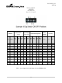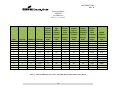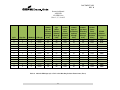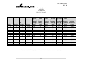
1
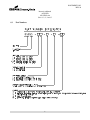
DOCUMENT 1025 REVISION B July 14, 2011 Instruction Manual Airside Guidance Sign AGS-LED 858 LED Series Sizes 1, 2, 3, 4 and 5 Cooper Industries Crouse-Hinds Division Airport Lighting Products 1200 Kennedy Road Windsor, CT 06095 Copyright © 2011 Cooper Technologies Company For Parts or Technical Service Call (860) 683-4300 DOCUMENT 1025 REV. B Instruction Manual AGS-LED 858 LED Series Sizes 1, 2, 3, 4 and 5 1 Revisions Revision Number Issue/Reissue Number Letter Description Checked Approved A A211-188 Initial Release of AGS-LED 858 Sign Manual MEG 6/8/11 B A211-218 Update to reflect new single conductor wiring SD 7/14/11 ii DOCUMENT 1025 REV. B Instruction Manual AGS-LED 858 LED Series Sizes 1, 2, 3, 4 and 5 2 Limited Product Warranty THE FOLLOWING WARRANTY IS EXCLUSIVE AND IN LIEU OF ALL OTHER WARRANTIES, WHETHER EXPRESS, IMPLIED OR STATUTORY, INCLUDING, BUT NOT BY WAY OF LIMITATION, ANY WARRANTY OF MERCHANTABILITY OR FITNESS FOR ANY PARTICULAR PURPOSE. Crouse-Hinds Airport Lighting Products (the “Company”) warrants to each original Buyer of Products manufactured by the Company that such Products are, at the time of delivery to the Buyer, free of material and workmanship defects, provided that no warranty is made with respect to: Any Product which has been repaired or altered in such a way, in Company’s judgment, as to affect the Product adversely; Any Product which has, in Company’s judgment, been subject to negligence, accident or improper storage; Any Product which has not been operated and maintained in accordance with normal practice and in conformity with recommendations and published specification of Company; and, Any Products, component parts or accessories manufactured by others but supplied by Company (any claims should be submitted directly to the manufacturer thereof). Crouse-Hinds Airport Lighting Products’ obligation under this warranty is limited to use of reasonable efforts to repair or, at its option, replace, during normal business hours, at any authorized service facility of Company, any Products which in its judgment proved not to be as warranted within the applicable warranty period. All costs of transportation of Products claimed not to be as warranted and of repaired or replacement Products to or from such service facility shall be borne by Purchaser. Company may require the return of any Product claimed not to be as warranted to one of its facilities as designed by Company, transportation prepaid by Purchaser, to establish a claim under this warranty. The cost of labor for installing a repaired or replacement product shall be borne by Purchaser. Replacement parts provided under the terms of this warranty are warranted for the remainder of the warranty period of the Products upon which they are installed to the same extent as if such parts were original components thereof. Warranty services provided under the Agreement does not assure uninterrupted operations of Products; Company does not assume any liability for damages caused by any delays involving warranty service. The warranty period for the Products is 24 months from date of shipment or 12 months from date of first use whichever occurs first. iii DOCUMENT 1025 REV. B Instruction Manual AGS-LED 858 LED Series Sizes 1, 2, 3, 4 and 5 3 Safety Notices This equipment is normally used or connected to circuits that may employ voltages which are dangerous and may be fatal if accidentally contacted by operating or maintenance personnel. Extreme caution should be exercised when working with this equipment. While practical safety precautions have been incorporated in this equipment, the following rules must be strictly observed: 3.1 Keep Away from Live Circuits Operating and maintenance personnel must at all times observe all safety regulations. Do not perform maintenance on internal components or service with power ON. WARNING: WARNING 3.2 DO NOT PERFORM MAINTENANCE ON INTERNAL COMPONENTS OR SERVICE WITH POWER ON. RESUSCITATION Maintenance personnel should familiarize themselves with the tech technique nique for resuscitation found in widely published manuals of first aid instruction. iv DOCUMENT 1025 REV. B Instruction Manual AGS-LED 858 LED Series Sizes 1, 2, 3, 4 and 5 4 Safety Symbols 4.1 Danger DANGER: DANGER 4.2 The hazard or unsafe practice will result in severe injury or death. Warning WARNING: WARNING 4.3 The hazard or unsafe practice could result in severe injury or death. Caution CAUTION: CAUTION 4.4 The hazard or unsafe practice could result in minor injury. Warning: Notice WARNING: NOTICE 4.5 Possibly dangerous situation, goods might be damaged. Warning : Important WARNING: IMPORTANT Helpful information. v DOCUMENT 1025 REV. B Instruction Manual AGS-LED 858 LED Series Sizes 1, 2, 3, 4 and 5 5 Test Equipment and Tools There is a wide variety of tools and equipment needed to safely and correctly perform airfield lighting equipment installation and maintenance. In addition to the obvious tools (screwdrivers, wrenches, etc.), there is a specialized equipment needed to do the job. Multimeter One of the most important pieces of test equipment is the Multimeter. It is used to measure voltages, currents, and resistances. Almost every single maintenance task requires the use of a multimeter at one point or another. A quality meter in good repair and calibration is a must because airfield lighting power distribution equipment produces non-sinusoidal waveforms, traditional average reading meters are inaccurate and have very limited use. Checking or adjusting equipment based upon incorrect current reading may dramatically reduce lamp life and adversely affect power equipment performance. A meter with TRUE RMS measuring capability and a current clamp-on probe is needed to accurately measure distorted or chopped waveforms. All meter manufacturers offer TRUE RMS measuring meters. The following is a short list of TRUE RMS Multimeters from Fluke: Manufacturer Fluke Model Number 87V, 287 Our recommended meter is the Fluke 87V with the Fluke I800 current clamp. Refer to the equipment manufacturer’s manuals for the proper use, maintenance and calibration (if necessary) of all meters. vi DOCUMENT 1025 REV. B Instruction Manual AGS-LED 858 LED Series Sizes 1, 2, 3, 4 and 5 6 Table of Contents 1 2 3 Revisions ............................................................................................................................... ii Limited Product Warranty .................................................................................................... iii Safety Notices ........................................................................................................................iv 3.1 Keep Away from Live Circuits .......................................................................................iv 3.2 RESUSCITATION .........................................................................................................iv 4 Safety Symbols ....................................................................................................................... v 4.1 Danger .............................................................................................................................. v 4.2 Warning............................................................................................................................ v 4.3 Caution ............................................................................................................................. v 4.4 Warning: Notice ............................................................................................................... v 4.5 Warning : Important ......................................................................................................... v 5 Test Equipment and Tools .....................................................................................................vi 6 Table of Contents................................................................................................................. vii 7 List of Figures and Tables .................................................................................................. viii 8 General Information ............................................................................................................... 1 8.1 General Description ......................................................................................................... 1 8.2 Classification of Signs...................................................................................................... 1 8.3 Part Numbers: .................................................................................................................. 2 9 Installation .............................................................................................................................. 3 10 Maintenance and Troubleshooting ......................................................................................... 6 10.1 General ............................................................................................................................. 6 10.2 Problem Solving Guide .................................................................................................... 7 10.3 Measuring Input Current (Signs Without Optional Power Switch) ............................... 10 10.4 Measuring Input Current (Signs With Optional Power Switch) .................................... 10 10.5 Checking Power Supply LED Cable .............................................................................. 11 10.6 10.7 Checking LED MODULE Cable Connections .............................................................. 12 Checking the First LED MODULE ............................................................................... 12 10.8 Checking the Second LED MODULE ........................................................................... 13 10.9 Continue Checking the Rest of the LED MODULES.................................................... 14 10.10 Replacing an LED MODULE ........................................................................................ 15 10.11 Sign PC Board P/N 62277 Calibration........................................................................... 17 10.12 Replacing Sign Power Supply Board & Heat Sink P/N 62277 ...................................... 17 11 Figures and Tables ................................................................................................................ 20 vii DOCUMENT 1025 REV. B Instruction Manual AGS-LED 858 LED Series Sizes 1, 2, 3, 4 and 5 7 List of Figures and Tables Figure 1. Single module sign ....................................................................................................... 20 Figure 2. Double module sign...................................................................................................... 21 Figure 3. Three module sign ........................................................................................................ 22 Figure 4. Four module sign .......................................................................................................... 23 Figure 5. Distance Marker ........................................................................................................... 24 Figure 6. Sign Options ................................................................................................................. 25 Figure 7. Heat Sink/LED Assembly showing wiring input and output connections ................... 26 Figure 8. LED Array Wiring, One Module Signs........................................................................ 27 Figure 9. LED Array Wiring, Two Module Signs ....................................................................... 28 Figure 10. LED Array Wiring, Three Module Signs ................................................................... 29 Figure 10. LED Array Wiring, Four Module Signs ..................................................................... 30 Figure 11. LED Array Wiring, Distance Marker ......................................................................... 31 Figure 12. Recommended Transformer Housing Location &Concrete Foundation/Pad Details 32 Figure 12a. Expanded left section of Figure 12 ........................................................................... 33 Figure 12b. Expanded right section of Figure 12 ........................................................................ 34 Figure 12c. Expanded top section of Figure 12 ........................................................................... 35 Figure 14. Concrete Foundation/Pad configurations, Sizes 2 ...................................................... 37 Figure 15. Concrete Foundation/Pad configurations: Two 4-Module Signs, Side by Side ......... 38 Figure 16. Sizes 3, & 5 Concrete Foundation/Pad Configurations .............................................. 39 Figure 18. Power Supply Box ...................................................................................................... 41 Figure 21. Power Supply Wiring Diagram .................................................................................. 42 Figure 22. Checking the Power Supply Output Voltage After Turn-Off..................................... 43 Table 1. Power Supply Switch and Jumper Selection (FERRO CCR) ........................................ 44 Table 2. Power Supply Switch and Jumper Selection (SERIES CCR) ....................................... 45 Table 3. AGS 858 LED Sign Style 2 VA Load & Matching Isolation Transformer (Ferro)....... 46 Table 4. AGS 858 LED Sign Style 3 VA Load & Matching Isolation Transformer (Ferro)....... 47 Table 5. AGS 858 LED Sign Style 5 VA Load & Matching Isolation Transformer (Ferro)....... 48 Table 6. AGS 858 LED Sign Style 2 VA Load & Matching Isolation Transformer (Series) ..... 49 Table 7. AGS 858 LED Sign Style 3 VA Load & Matching Isolation Transformer (Series) ..... 50 Table 8. AGS 858 LED Sign Style 5 VA Load & Matching Isolation Transformer (Series) ..... 51 Table 9. Style 2 - Three step regulator currents ........................................................................... 52 Table 10. Style 3 - Five step regulator currents ........................................................................... 52 Table 11. Style 5 – Fixed regulator current ................................................................................. 52 Table 12. Power Supply Faults .................................................................................................... 53 Table 13. Parts List ...................................................................................................................... 54 Table 14. Estimated max sustained force on the sign body (Does not include safety margin) ... 55 viii DOCUMENT 1025 REV. B Instruction Manual AGS-LED 858 LED Series Sizes 1, 2, 3, 4 and 5 8 General Information 8.1 General Description Crouse-Hinds Airport Lighting Products, “AIRSIDE” internally illuminated LED Taxiway and Runway Signs provide outstanding message visibility, day or night. White on Red and Yellow on Black and Black on Yellow color combinations may be ordered with any desired message. Signs are available as single or double faced and are provided with retro-reflective sign face. For further information on Taxiway Signs and their use, consult the latest revision FAA Advisory Circulars AC 150/5220-9, AC 150/5340-18, and AC 150/5345-44. 8.2 Classification of Signs The signs covered in this manual are designed and manufactured in accordance with the requirements of FAA Advisory Circular AC 150/5345-44J. Specifications for Taxiway and Runway Signs and conform to the following classifications as indicated in paragraph 1.2 of the above Advisory. Type L-858Y – Direction destination and boundary sign – black legend on a yellow background. Type L-858R – Mandatory instruction sign white legend on a red background. Type L-858L – Taxiway and runway location sign yellow legend and border on a black background. Type L-858B –Runway Distance Remaining sign with a white legend on a black background. Type L858C – Taxiway Ending Marker sign yellow strips on black background (2 module sign only) A sign may consist of multiple arrays of the above messages. NOTE: Size 5 information in this manual is the same as the Size 3 single module unless noted otherwise. P/N Sizes 858S5-1X-X-X-X-XX Size 1 – 12 inch legend (small body) 858S5-2X-X-X-X-XX Size 2 – 15 inch legend (mid-size body) 858S5-3X-X-X-X-XX Size 3 – 18 inch legend (large body) 858S5-4X-X-X-X-XX Size 4 – 40 inch legend (large body DMS numerals and AGM symbol) 858S5-5X-X-X-X-XX Size 5 – 25 inch legend (large body DMS numerals only) CAT. # FAA Styles -3 Style 2 – For operation from a 3 step series lighting circuit (4.8 to 6.6 amperes) -5 Style 3 – For operation from a 5 step series lighting circuit (2.8 to 6.6 amperes) -1 Style 5 – A (fixed) 5.5 ampere series lighting circuit Class 2 – For operation from -40ºC to +55ºC (+131ºF) Mode 2 – Sign for use in areas subjected to wind speed of up to 200 mph (322 km/h) 1 DOCUMENT 1025 REV. B Instruction Manual AGS-LED 858 LED Series Sizes 1, 2, 3, 4 and 5 8.3 Part Numbers: 2 DOCUMENT 1025 REV. B Instruction Manual AGS-LED 858 LED Series Sizes 1, 2, 3, 4 and 5 9 Installation WARNING: NOTICE Sign foundations/pad and their design are the responsibility of the installer and/or airport and recommendations/suggestions herein are for guidance only. Transformer housing and baseplates and/or covers, series isolation transformers, primary connector kits, series isolation transformer secondary cable extender, series isolation consolidating harness (if required), heat shrink kits, grounding rods, ground wire and connectors, floor flange anchor bolts and hardware are not included as part of the sign. Underlined items may be ordered from Crouse-Hinds Airport Lighting. a. Refer to FAA AC 150-5345-18F section 14 for Taxiway Guidance Sign location and for the perpendicular distance from the defined pavement edge to the near side of the sign. Similarly, see section 25 of FAA AC 150-5345-18F for Runway Distance Remaining Sign location and perpendicular distance from the defined pavement edge to the near side of the sign. WARNING: IMPORTANT b. FAA specifications and Engineering Briefs may be obtained by searching the FAA web site: www.faa.gov. See Figures 12-17 for suggested concrete foundation/pad. Concrete foundations/pads should be of adequate mass, reinforcement, and psi strength rating for the maximum sustained force on the sign body and floor flange anchors must endure at its maximum plus a safe safety ty margin. The concrete foundation/pad should be installed in soil conditions that will help facilitate drainage and foundation/pad support. The floor flange anchor bolt material should also meet the maximum sustained force on the sign body plus a safety margin and must be ½ inch in diameter for use with the 25684-1 Floor Flange. See Table 14 for estimated maximum sustained force on the sign body. c. Concrete foundations/pads should extend at least 12 inches below the local frost line. Contact your local or regional building inspector if the depth is unknown for your area. The foundation/pad should extend at least 1 foot beyond the sign body to minimize damage from mowers. 3 DOCUMENT 1025 REV. B Instruction Manual AGS-LED 858 LED Series Sizes 1, 2, 3, 4 and 5 d. The concrete foundation/pad should be not more than 1 inch above grade in or order der to maintain the 3 inch maximum overall height above grade to the point of frangibility per FAA Engineering Brief no. 79. See the Engineering Brief for acceptable grading around the foundation/pad. The foundation/pad pad must be level. e. It is recommended that the contractor who is to install the concrete foundation/pad use cast in place anchor bolts. The threaded portion of the anchor bolts should be 1-5/8 inches minimum to 1-7/8 maximum above the top of the concrete foundation/pad (See Figures 12, 12a-12c). This requires that the anchor bolts be installed accurately as shown in the concrete foundation/pad dimensions Figure 13. The clearance holes on the floor flange are 5/8 inch diameter on a 4.75 inch diameter bolt circle for use with ½ inch anchor bolts. f. The concrete foundation/pad should include the series isolation transformer housing. It is recommended that this housing not be placed under the sign power leg to allow access to the series isolation transformer and connections for ease of troubleshooting and servicing (See Figures 12, 12a12c). This housing would be on the side closest to the Taxiway or Runway. A 2 inch conduit elbow with threaded coupling attached at sign end would exit from the transformer housing side to the foundation/pad and be flush with the with the top of the concrete foundation/pad grade level centered between the floor flange bolts nearest the Taxiway or Runway side of the sign. The sign as viewed will have the circuit card box to the right on the “A” side of the sign, which is closest to the Taxiway or Runway side of the sign. If the location requires an add additional itional housing to accommodate multiple messages, then the separation distance between these signs housings can be 3 inches minimum to 12 inches maximum (FAA AC 150-5345-44J 3.2.5.2 a.). This first sign body housing (farthest from the adjacent Taxiway) will have the circuit card box to the left on the “A” side of the sign. The sign side identification is important with regards to its sign panel legend. A ggrounding rounding rod and clamp should be installed at the end opposite the circuit card box in order to ground the sign housing. This grounding rod must not be connected to the field counterpoise. DANGER: DANGER g. Lock out electrical power to the series loop that will power the sign at its source before attempting any electrical connections/splices. Make electrical connections to the series loop power using L-823 Primary Connector Kits. Attach the primary connectors to the appropriate size L-830 Series Isolation Transformer (See Tables 3-8). These primary connections (single pin plug or receptacle) should have Heat Shrink Kits applied over their connections to prevent disconnection and water from entering the cables. If two Series Isolation Transformers are required to be attached in series to obtain the correct wattage required for the sign, all primary lead connections should have Heat Shrink Kits applied. Two Series Isolation Transformers connected in series together will require a Consolidating Harness (Crouse-Hinds Part Number 26811-27) at the transformer secondary connectors (two pin receptacle) to series them together. Use electrical tape around the connections to prevent accidental disconnection. The Series 4 DOCUMENT 1025 REV. B Instruction Manual AGS-LED 858 LED Series Sizes 1, 2, 3, 4 and 5 Isolation Transformer should be placed on a brick in order to isolate the transformer from direct contact with metal. The Series Isolation Transformer secondary cable should then be inserted from inside the housing up the conduit elbow. Using the two 40762 retainers supplied with the sign (looks like a cupped washer with a slot), placing one below the secondary cable receptacle (L-823 Style 8, looks like a ball), and one above. The bottom cupped washer sits on the conduit elbow top inside the threaded conduit coupling and prevents the sec secondary ondary cable from dropping back down the conduit. The top cupped washer prevents the secondary cable from being pulled out of the ground allowing the sign power cord to disconnect if the sign is impacted and shears off at its frangible couplings. If a consolidating harness is used or a secondary cable extension (use electrical tape around connection) is required, use the 25003 (split clamp with screws and hex nuts) retainer supplied with the sign. Secure this retainer, flat side down away from sign, around the secondary end (L-823 Style 7, looks like a straight tube) that will exit the conduit elbow. The top of the secondary receptacle should be at least ¼ inch below the conduit elbow threaded coupling top surface. WARNING: IMPORTANT Check the sig sign n for shipping damage upon arrival and in all cases, check for damage prior to installation. h. Lower the sign with the legs and flanges into place. Plug the sign power cable plug into the secondary receptacle inside the conduit elbow while lowering. Check the sign itself with a long carpenter’s level to be sure it is level. As an alternate, remove the floor flanges and frangible couplings from the sign, unscrewing the frangible couplings from the floor flanges. Install the floor flanges onto the sign anchor bolts. Level the floor flanges for ease of installation of the sign. A long carpenter’s level can be placed across the top of the floor flanges to be sure they are all in line and level. Do not tighten the anchor nuts tight (only finger-tight) uuntil ntil the frangible couplings are installed back into to floor flanges. Note: Some vertical adjustments can be obtained by rotating the floor flanges a turn or two on the frangible coupling. i. Make sure all flanges are in full contact and sit flush on the pad before tightening the anchor bolts. Shim and grout as required. Once the sign has been leveled, attach the sign tether to the closest anchor bolt and tighten all the anchor nuts securely. (Note: Anchor hardware is not supplied with the sign.) Anchor hardware should be corrosion resistant. The sign body must not be bent or distorted due to an uneven installation procedure. Install a bare #14 AWG minimum copper ground wire to the sign ground stud (stud located on sign bottom extrusion exterior and acc accepts epts #4 through #14 AWG) and the other end to the grounding rod clamp. j. The sign is shipped set for a Ferro-resonant Type L-828 Regulator as illustrated in Table 1. For other Regulator types, set sign power supply circuit card jumper according to Table 2. k. Return power to series circuit and verify sign illuminates through all Regulator brightness steps. 5 DOCUMENT 1025 REV. B Instruction Manual AGS-LED 858 LED Series Sizes 1, 2, 3, 4 and 5 10 Maintenance and Troubleshooting WARNING: WARNING 10.1 Remove Power Before Attempting Any Servicing. General Work on electrical circuits shoul should d be done only by a qualified electrician with a working knowledge of airfield lighting circuits. Trouble-shooting is accomplished by means of process of elimination. It should be checked that the POWER is OFF and secured, and once one solution is tried, POWER is reapplied. Then POWER turned OFF and secured and another solution tried, etc. Repeat this until the problem is solved. It is also assumed that the circuit is in proper working order from the isolation transformer secondary connector (L-823 style 7or 8 receptacle) all the way to and including the power source. Use of a calibrated true RMS-reading multi-meter with a current sensing clamp-on attachment will aid in the trouble shooting of electrical circuits. Warning: Only use OEM replacement sign legend panels WARNING: NOTICE Only use OEM replacement sign legend panels. The entire message element must be replaced per FAA AC 150-5345-44J 3.2.5.10.2. Our proprietary process replacement panels meet the photometric and wind loading requirement requirementss of the sign as certified to FAA AC 1505345-44J. 6 DOCUMENT 1025 REV. B Instruction Manual AGS-LED 858 LED Series Sizes 1, 2, 3, 4 and 5 CAUTION: CAUTION Do not over tighten hex nut on stud retaining bridge rectifier. 8in-lbs max. (See Figure 18) Also, remover carriers from thermal pad adhesive surfaces before installing. WARNING: IMPORTANT When tightening cover screws, do not use power drivers as you may exceed the maximum torque of 75 in-lbs on the cover screws. DANGER: DANGER 10.2 When replacing parts inside the circuit box or sign housing, lock out series circuit power at its source. Problem Solving Guide PROBLEM (P.1) Sign will not light POSSIBLE CAUSE CORRECTIVE ACTION No input current. (LEDs on Power Measure input current Supply board not lit) according to Sections 10.3 and 10.4. If the measured input current is not within spec (see Tables 9-11), check CCR, isolation transformer, and primary power connections. 7 DOCUMENT 1025 REV. B Instruction Manual AGS-LED 858 LED Series Sizes 1, 2, 3, 4 and 5 PROBLEM POSSIBLE CAUSE CORRECTIVE ACTION (P.2) Sign will not light Input current is below or exceeds specification. (Input current is specified between 2.8 and 6.6 amps using a true RMS Ammeter. L858 Power Supply indicator RED LEDs D4 is ON, and D7 is OFF; Table 12) Adjust CCR current (See Tables 9-11 and/or replace isolation transformer with appropriate wattage for sign (see Tables 3-8). (P.3) Sign will not light Optional ON/OFF switch in OFF position Turn switch to ON position. (P.4) Sign will not light Power Supply Circuit Card +15V supply failed (See Table 12) Verify Green LED D29 is lit. Replace Power Supply Board if D29 is not lit.(Section 10.12) (P.5) Sign will not light Power Supply Circuit Card +3.3V supply failed (See Table 12) Verify Green LED D11 is lit. Replace Power Supply Board if D11 is not lit (section 10.12). (P.6) Sign will not light Loose/broken wire(s)/missing connections Verify Power Supply connections match Power Supply Wiring Diagram (Figures 18 & 21). (P.7) Sign will not light Output Electrical Open Circuit (See Table 12) Verify LED cable connectors are properly seated in their respective receptacles; reseat if necessary (See Sections 10.5 & 10.6) (P.8) Sign will not light LED MODULE(s) mounted/wired incorrectly Verify that LED MODULES are mounted and wired according to LED Array Wiring Diagram. (See Figures 7-11 and Sections 10.7-10.9) (P.9) Sign will not light LED MODULE(s) open circuit Replace suspected open circuit failure (Assumes P.7 Action taken) LED MODULE with spare known good LED 8 DOCUMENT 1025 REV. B Instruction Manual AGS-LED 858 LED Series Sizes 1, 2, 3, 4 and 5 PROBLEM POSSIBLE CAUSE CORRECTIVE ACTION MODULE(s) (See Sec 10.10) (P.10) Upon applying power, sign momentarily lights and then turns off. Incorrect LED Power Supply Circuit Board Switch Configuration Verify/Set Power Supply Board Switches and jumpers are set according to Table 1 (Ferro CCR) or Table 2 (Series CCR) (P.11) Upon applying power, sign momentarily lights and then turns off. LED MODULE Voltage has dropped 25% below the calibrated output voltage (See Table 12). Replace any LED MODULE(s) with non-lit LEDs and re-calibrate the LED Power Supply. (See Sections 10.10 & 10.11) (P.12) Upon applying power, sign momentarily lights and then turns off. LED MODULE Voltage is greater than 125% of the expected calibrated output voltage (See Table 12). Verify/Set Power Supply Board Switches and jumpers are set according to Table 1 (Ferro CCR) or Table 2 (Series CCR) (P.13) Sign flickering Incorrect LED Power Supply Circuit Board Jumper Setting. Verify/Set Jumpers JP1 and JP2 according to the Table 1 (FERRO CCR) or Table 2 (Series CCR) (P.14) Sign flickering Incorrect Isolation Transformer Replace with Isolation transformer that matches sign type, size, #modules. (See Tables 3-8) 9 DOCUMENT 1025 REV. B Instruction Manual AGS-LED 858 LED Series Sizes 1, 2, 3, 4 and 5 10.3 Measuring Input Current (Signs Without Optional Power Switch) WARNING: WARNING Failure to turn off power to the sign and wait five minutes could result in severe injury or death. Turn off power to the sign by turning off the corresponding Constant Current Regulator (CCR) power. (WARNING: Wait five minutes after sign power is turned off to service the sign. This will allow any residual high voltage stored in Power Supply PCB components to bleed off. ) With your multimeter set to DC Volts, verify that the Power Supply Output Voltage is less than 30-VDC at TP6 (Positive lead) and TP3 (Negative Lead) as indicated in Figure 22. If the Power Supply Output Voltage is greater than 30-VDC, then you must wait until the Power Supply Output Voltage drops below 30-VDC before you proceed with the next step. Open Power Supply cover (See Figure 18). Disconnect female crimp receptacle at CN17 from Power Supply Board. (Note: When removing female crimp receptacle, grasp by the terminal, not the wire.) Disconnect female crimp receptacle from CN18 and connect to CN17. Place current clamp around primary power wire and connect to a true rms current meter. Turn on power to the CCR. Current should measure between 2.7-ARMS and 6.7-ARMS depending on the CCR current level or current step. Upon completing the measurement of the input current, turn off power to the CCR. Remove the current clamp. Disconnect the female crimp receptacle at CN17 and reconnect to CN18. Reconnect the female crimp receptacle attached to wire BRPH to CN18. Close the Power Supply Box cover. 10.4 Measuring Input Current (Signs With Optional Power Switch) WARNING: WARNING Failure to turn off power to the sign and wait five minutes could result in severe injury or death. Turn off power to sign by toggling sign power switch to the off position (See Figure 6). Turn off power to the sign. (WARNING: Wait five minutes after sign power is turned off to service the sign. This will allow any residual high voltage stored in Power Supply PCB components to bleed off. ) With your multimeter set to DC Volts, verify that the Power Supply Output Voltage is less than 30-VDC at TP6 (Positive lead) and TP3 (Negative Lead) as indicated in Figure 22. If the Power Supply Output 10 DOCUMENT 1025 REV. B Instruction Manual AGS-LED 858 LED Series Sizes 1, 2, 3, 4 and 5 Voltage is greater than 30-VDC, then you must w wait ait until the Power Supply Output Voltage drops below 30-VDC before you proceed with the next step. Open the Power Supply Box cover. Place current clamp around one of the wires connected to the switch labeled with switch marker PWR. Connect the current cclamp lamp to the true RMS current meter. Measure the input current. Current should measure between 2.7-ARMS and 6.7-ARMS depending on the CCR current level or current step. Upon completing the measurement of the input current, remove current clamp and close Power Supply Box cover. 10.5 Checking Power Supply LED Cable WARNING: WARNING Failure to turn off power to the sign and wait five minutes could result in severe injury or death. Turn off power to the sign. (WARNING: Wait five minutes after sign power is turned off to service the sign. This will allow any residual high voltage stored in Power Supply PCB components to bleed off. ) With your multimeter set to DC Volts, vverify erify that the Power Supply Output Voltage is less than 30-VDC at TP6 (Positive lead) and TP3 (Negative Lead) as indicated in Figure 21. If the Power Supply Output Voltage is greater than 30-VDC, then you must wait until the Power Supply Output Voltage drops below 30-VDC before you proceed with the next step. Remove the sign top cover bolts and then lift the top cover from the sign. Remove the front face from the sign. Check the Power Supply LED Cable for visible damage. Make sure the Power Supply LED cable connector is properly seated in CN9 at the Power Supply Board (see Figure 18). Verify that the Power Supply LED cable connector connects to the input connector of the first LED MODULE and is properly seated in the input connector housing. The LED MODULE input connector and the output connector are clearly marked with inward pointing and outward pointing black arrows, respectively, on the LED MODULE PCB (see Figure 7). 11 DOCUMENT 1025 REV. B Instruction Manual AGS-LED 858 LED Series Sizes 1, 2, 3, 4 and 5 10.6 Checking LED MODULE Cable Connections WARNING: WARNING Failure to turn off power to the sign and wait five minutes could result in severe injury or death. Turn off power to the sign by turning off the corresponding Constant Current Regulator (CCR) power. (WARNING: Wait five minutes after sign power is turned off to service the sign. This will allow any residual high voltage stored in Power Supply PCB components to bleed off.) With your multimeter set to DC Volts, verify that the Power Supply Output Voltage is less than 30-VDC at TP6 (Positive lead) and TP3 (Negative Lead) as indicated in Figure 22. If the Power Supply Output Voltage is greater than 30-VDC, then you must wait until the Power Supply Output Voltage drops below 30-VDC before you proceed with the next step. The LED MODULES are electrically wired in series. This means that if any of the cable connectors are improperly seated in their respective LED MODULE housing, then no current can flow through any of the LED MODULES and subsequently the sign will not light. Therefore, verify that all cable connectors are properly seated in their housing and that the output of one LED MODULE (indicated by the outward pointing arrow at the LED MODULE connector Figure 7) is connected to the input of the next LED MODULE (indicated by the inward pointing arrow at the LED MODULE connector- Figure 7). The Last LED MODULE in the series string is terminated with a black return connector & cable assembly(See Figure 7-11). Verify that the black terminator cable connector is properly inserted into the connector housing at the Last LED MODULE output connector (indicated by the inward pointing arrow). 10.7 Checking the First LED MODULE WARNING: WARNING Failure to turn off power to the sign and wait five minutes could result in severe injury or death. 12 DOCUMENT 1025 REV. B Instruction Manual AGS-LED 858 LED Series Sizes 1, 2, 3, 4 and 5 Turn off power to the sign by turning off the corresponding Constant Current Regulator (CCR) power. (WARNING: Wait five minutes after sign power is turned off to service the sign. This will allow any residual high voltage stored in Power Supply PCB components to bleed off.) With your multimeter set to DC Volts, verify that the Power Supply Output Voltage is less than 30-VDC at TP6 (Positive lead) and TP3 (Negative Lead) as indicated in Figure 22. If the Power Supply Output Voltage is greater than 30-VDC, then you must wait until the Power Supply Output Voltage drops below 30-VDC before you proceed with the next step. Remove the black return cable connector from the last LED MODULE output cable connector (see Figures 7-11 & 20). Replace the output cable connector in the first LED MODULE with the black return cable connector. Turn on main power. If the first LED MODULE momentarily lights and then turns off, then the first LED MODULE and the Power Supply LED cable and Power Supply board are operating normally. Turn off main power to the sign. Wait five minutes for the power supply voltages to dissipate. Verify that the output voltage is less than 30-VDC with a multimeter as described in the opening paragraph of this section. Replace the black return cable connector with the first LED MODULE output cable connector. If the sign does not light at all, then re replace place the LED MODULE #1 and/or the cable connecting from the output of the Power Supply to the input of LED MODULE #1(see Section 10.10). Then repeat the test described above in this section. 10.8 Checking the Second LED MODULE WARNING: WARNING Failure to turn off power to the sign and wait five minutes could result in severe injury or death. Turn off power to the sign by turning off the corresponding Constant Current Regulator (CCR) power. (WARNING: Wait five minutes after sign power is turned off to service the sign. This will allow any residual high voltage stored in Power Supply PCB components to bleed off.) With your multimeter set to DC Volts, verify that the Power Supply Output Voltage is less than 30-VDC at TP6 (Positive lead) and TP3 (Negative Lead) as indicated in Figure 22. If the Power Supply Output Voltage is greater than 30-VDC, then you must wait until the Power Supply Output Voltage drops below 30-VDC before you proceed with the next step. Remove the black return cable connector from the last LED MODULE output cable connector (see Figure 20). Replace the output cable connector in the second LED MODULE with the black return cable connector. Turn on main power to the sign. If both LED MODULES momentarily light and then turn off 13 DOCUMENT 1025 REV. B Instruction Manual AGS-LED 858 LED Series Sizes 1, 2, 3, 4 and 5 or stays lit, then the second LED MODULE and the cable from the first LED MODULE to the second LED MODULE are operating normally. Turn off main power to the sign. Wait five minutes for the high voltage to dissipate. Verify that the output voltage is less than 30-VDC with a multimeter as described in the opening paragraph of this section. Replace the black return cable connector with the first LED MODULE output cable connector. Replace the black return cable connector in the output connector housing of the last LED MODULE. If the sign does not light at all, then replace the second LED MODULE and/or the cable connecting from the output connector of LED MODULE #1 to the input of LED MODULE #2 (see Section 10.10). Then repeat the test outlined above in this section. 10.9 Continue Checking the Rest of the LED MODULES It is assumed that the first two LED MODULES have been checked successfully as described in previous two sections. For signs with more than two LED MODULES, continue checking the remaining LED MODULES one at a time and in numerical sequence (e.g. LED MODULE #3, LED MODULE #4….LED MODULE #Last). Use the same method as we have outlined in previous section. For example, suppose we have a sign with 6 LED MODULES (See Size 2, 2-Modules, Figure 9) and we have checked all the LED MODULES in sequence from 1 to from 4 and found that the sign momentarily lit. Then we would use the following procedure to test the 5th LED MODULE. WARNING: WARNING Failure to turn off power to the sign and wait five minutes could result in severe injury or death. Turn off power to the sign by turning off the corresponding Constant Current Regulator (CCR) power. (WARNING: Wait five minutes after sign power is turned off to service the sign. This will allow any residual high voltage stored in Power Supply PCB components to bleed off.) With your multimeter set to DC Volts, verify that the Power Supply Output Voltage is less than 30-VDC at TP6 (Positive lead) and TP3 (Negative Lead) as indicated in Figure 22. If the Power S Supply upply Output Voltage is greater than 30-VDC, then you must wait until the Power Supply Output Voltage drops below 30-VDC before you proceed with the next step. Remove the black return cable connector from the 6th LED MODULE output cable connector (see Figure 20). Replace the output cable connector in the LED MODULE #5 with the black return cable connector. 14 DOCUMENT 1025 REV. B Instruction Manual AGS-LED 858 LED Series Sizes 1, 2, 3, 4 and 5 Turn on main power to the sign. If LED MODULES #1 to #5 momentarily light and then turn off, then the LED MODULE #5 and the cable from the LED MODULE #4 to the LED MODULE #5 are operating normally. WARNING: WARNING Failure to turn off power to the sign and wait five minutes could result in severe injury or death. Turn off main power to the sign. Wait five minutes for the high voltage to dissipa dissipate. te. Verify that Power Supply Output Voltage measures less than 30-VDC, as described above. Replace the black return cable connector with the LED MODULE #5 output cable connector. Replace the black return cable connector into the output connector housing of the 6th LED MODULE. If the sign does not light at all, then replace the LED MODULE #5 and/or the cable connecting from the output connector of LED MODULE #4 to the input of LED MODULE #5 (see Section 10.10). Then repeat the test as described in this section. 10.10 Replacing an LED MODULE In the case where an LED MODULE has failed and needs to be replaced use the following instructions: INSTRUCTIONS FOR REPLACING AN LED MODULE The following instructions assume that the sign front face is removed and that the failed LED MODULE has been previously identified. WARNING: WARNING Failure to turn off power to the sign and wait five minutes could result in severe injury or death. Current nt Regulator (CCR) 1. Turn off power to the sign by turning off the corresponding Constant Curre power. (WARNING: Wait five minutes after sign power is turned off to service the sign. This will allow any residual high voltage stored in Power Supply PCB components to bleed off.) 15 DOCUMENT 1025 REV. B Instruction Manual AGS-LED 858 LED Series Sizes 1, 2, 3, 4 and 5 2. With your multimeter set to DC Volts, verify tha thatt the Power Supply Output Voltage is less than 30VDC at TP6 (Positive lead) and TP3 (Negative Lead) as indicated in Figure 22. If the Power Supply Output Voltage is greater than 30-VDC, then you must wait until the Power Supply Output Voltage drops below 30-VDC before you proceed with the next step. 3. Carefully remove the input and output cables from the failed LED MODULE. (Mark the cable connected to the LED MODULE input connector. Note: The input connector on the LED MODULE is denoted by a black arrow pointing toward the input connector (see Figure 7). 4. Loosen and remove the nuts on the LED MODULE mounting bracket bolts. Remove the LED MODULE bracket bolts with one hand while support the LED MODULE with your other hand. 5. Carefully remove the failed LED MODULE from the LED MODULE mounting bracket. 6. Mount the replacement LED MODULE into the mounting bracket such that the holes in the LED MODULE heat sink are aligned with the mounting bracket holes. (Note: The replacement LED MODULE input connector should be closest to the marked input cable connector.) 7. Push the mounting bracket bolts through the mounting bracket and the LED MODULE heat sink holes. 8. Attach nuts to the mounting bracket bolts and tighten. 9. Gently slide the input cable connector into the replacement LED MODULE connector input housing. 10. Likewise, slide the output cable connector into the replacement LED MODULE output connector housing. 11. The LED MODULE replacement is complete. 12. Power Supply Board must be re-calibrated after replacing an LED MODULE (see Section 10.11). WARNING: IMPORTANT Power Supply Board must be re-calibrated after replacing an LED MODULE (see Section 10.11). 16 DOCUMENT 1025 REV. B Instruction Manual AGS-LED 858 LED Series Sizes 1, 2, 3, 4 and 5 10.11 Sign PC Board P/N 62277 Calibration The 62277 PC Board doesn’t normally need to be calibrated in the field unless an LED MODULE is replaced. WARNING: IMPORTANT In this section, it is assumed that the Sign PC Board P/N 62277 is correctly configured for this particular sign (see Table 1or 2) and that the sign lights continuously when m main ain power is applied in the normal mode of operation (SW3-1 = OFF). INSTRUCTIONS FOR CALIBRATION OF 62277 PC BOARD: 1. Turn off main power to the sign. 2. Open the Power Supply Cover and locate SW3-1 on the Power Supply Board (See Figure 18) 3. On the Power Supply Board, set switch SW3-1 to the ON position. 4. Apply main power to the sign. Green LED D3 will flash ON/OFF slowly for approximately three seconds to indicate the beginning of the calibration process. During calibration, D3, will remain OFF. At the conclusion of the calibration process, D3 remain constant ON (see Figure 18). 5. If D3 does not light and remain constant, then calibration has failed. Based on the assumption listed under WARNING above, replace the power supply board (See section 10.12) 5. Turn off the main power to the sign. 6. Set SW3-1 to the OFF position. 7. Close the Power Supply cover. 8. The Power Supply Board is now calibrated to the sign. 10.12 Replacing Sign Power Supply Board & Heat Sink P/N 62277 In this section, it is assumed that the sign has failed and the trouble shooting guide recommends replacement of the Power Supply Board. INSTRUCTIONS FOR REPLACING 62277 PC BOARD & HEAT SINK: 17 DOCUMENT 1025 REV. B Instruction Manual AGS-LED 858 LED Series Sizes 1, 2, 3, 4 and 5 WARNING: IMPORTANT Power Supply Board must be re-calibrated after replacement. (see Section 10.11). 1. Turn off power to the sign by turning off the corresponding Constant Current Regulator (CCR) power. (WARNING: Wait five minutes after sign power is turned off to service the sign. This will allow any residual high voltage stored in Power Supply PCB components to bleed off.) WARNING: WARNING Failure to turn off power to the sign and wait five minutes could result in severe injury or death. 2. With your multimeter set to DC Volts, verify that the Power Supply Output Volta Voltage ge is less than 30VDC at TP6 (Positive lead) and TP3 (Negative Lead) as indicated in Figure 22. If the Power Supply Output Voltage is greater than 30-VDC, then you must wait until the Power Supply Output Voltage drops below 30-VDC before you proceed with the next step. 3. Remove input power cabling at CN1, CN2, CN3, CN11, CN17, & CN18 (See Figure 15). 4. Remove LED Power Supply Cable at CN9 (See Figure 15). 5. Remove the three nuts that secure the main heat sink to the Power Supply Box. 6. Remove the six screws that fasten the Power Supply Board onto the Power Supply Box. 7. Remove the Power Supply Board Assembly by sliding the attached main heat sink off the mounting studs extending from the side of the Power Supply Box. 8. Slide the new Power Supply Boa Board rd onto the mounting studs extending from the side of the Power Supply Box. 9. Fasten board to the Power Supply Box with six mounting screws. 10. Attach the three nuts that secure the heat sink to the studs extending from the side of the Power Supply Box. 11. Connect the LED Power Supply cable at CN9. 12. Connect the input power cabling at CN1, CN2, CN3, CN11, CN17, & CN18. 13. Set the jumpers JP1 & JP2 for the sign style, size, and number of modules as shown in Table 1 or 2. (For locaction, see Figure 18) 18 DOCUMENT 1025 REV. B Instruction Manual AGS-LED 858 LED Series Sizes 1, 2, 3, 4 and 5 14. Set DIP switches SW1, SW2, & SW3for the sign style, size, and number of modules as shown in Table 1 or 2. (For locations Figure 18) 15. The Power Supply Board and Heat Sink replacement is complete 19 DOCUMENT 1025 REV. B Instruction Manual AGS-LED 858 LED Series Sizes 1, 2, 3, 4 and 5 11 Figures and Tables Figure 1. Single module sign 20 DOCUMENT 1025 REV. B Instruction Manual AGS-LED 858 LED Series Sizes 1, 2, 3, 4 and 5 Figure 2. Double module sign 21 DOCUMENT 1025 REV. B Instruction Manual AGS-LED 858 LED Series Sizes 1, 2, 3, 4 and 5 Figure 3. Three module sign 22 DOCUMENT 1025 REV. B Instruction Manual AGS-LED 858 LED Series Sizes 1, 2, 3, 4 and 5 Figure 4. Four module sign 23 DOCUMENT 1025 REV. B Instruction Manual AGS-LED 858 LED Series Sizes 1, 2, 3, 4 and 5 Figure 5. Distance Marker 24 DOCUMENT 1025 REV. B Instruction Manual AGS-LED 858 LED Series Sizes 1, 2, 3, 4 and 5 Figure 6. Sign Options 25 DOCUMENT 1025 REV. B Instruction Manual AGS-LED 858 LED Series Sizes 1, 2, 3, 4 and 5 Figure 7. Heat Sink/LED Assembly showing wiring input and output connections 26 DOCUMENT 1025 REV. B Instruction Manual AGS-LED 858 LED Series Sizes 1, 2, 3, 4 and 5 Figure 8. LED Array Wiring, One Module Signs (Reference Figure 7 for LED array orientations) 27 DOCUMENT 1025 REV. B Instruction Manual AGS-LED 858 LED Series Sizes 1, 2, 3, 4 and 5 Figure 9. LED Array Wiring, Two Module Signs (Reference Figure 7 for LED array orientations) 28 DOCUMENT 1025 REV. B Instruction Manual AGS-LED 858 LED Series Sizes 1, 2, 3, 4 and 5 Figure 10. LED Array Wiring, Three Module Signs (Reference Figure 7 for LED array orientations) 29 DOCUMENT 1025 REV. B Instruction Manual AGS-LED 858 LED Series Sizes 1, 2, 3, 4 and 5 Figure 10. LED Array Wiring, Four Module Signs (Reference Figure 7 for LED array orientations) 30 DOCUMENT 1025 REV. B Instruction Manual AGS-LED 858 LED Series Sizes 1, 2, 3, 4 and 5 Figure 11. LED Array Wiring, Distance Marker (Reference Figure 7 for LED array orientations) 31 DOCUMENT 1025 REV. B Instruction Manual AGS-LED 858 LED Series Sizes 1, 2, 3, 4 and 5 Figure 12. Recommended Transformer Housing Location &Concrete Foundation/Pad Details 32 DOCUMENT 1025 REV. B Instruction Manual AGS-LED 858 LED Series Sizes 1, 2, 3, 4 and 5 Figure 12a. Expanded left section of Figure 12 33 DOCUMENT 1025 REV. B Instruction Manual AGS-LED 858 LED Series Sizes 1, 2, 3, 4 and 5 Figure 12b. Expanded right section of Figure 12 34 DOCUMENT 1025 REV. B Instruction Manual AGS-LED 858 LED Series Sizes 1, 2, 3, 4 and 5 Figure 12c. Expanded top section of Figure 12 35 DOCUMENT 1025 REV. B Instruction Manual AGS-LED 858 LED Series Sizes 1, 2, 3, 4 and 5 Figure 13. Concrete Foundation/Pad configurations, Size 1 36 DOCUMENT 1025 REV. B Instruction Manual AGS-LED 858 LED Series Sizes 1, 2, 3, 4 and 5 Figure 14. Concrete Foundation/Pad configurations, Size 2 37 DOCUMENT 1025 REV. B Instruction Manual AGS-LED 858 LED Series Sizes 1, 2, 3, 4 and 5 Figure 15. Concrete Foundation/Pad configurations: Two 4-Module Signs, Side by Side NOTE, IF 3 SIGNS ARE USED IN AN ARRAY, MAKE SEPARATION DISTANCE 12 INCHES TO ALLOW CIRCUIT CARD BOX DOOR TO OPEN IN THIS SPACE WHEN ANOTHER CIRCUIT CARD BOX IS MOUNTED IN THIS SAME SPACE UTILIZED ON ADJACENT SIGN. THIS WILL ALLOW THIS SEPARATION DISTANCE TO REMAIN WITHIN THE FAA SPECIFICATION. 38 DOCUMENT 1025 REV. B Instruction Manual AGS-LED 858 LED Series Sizes 1, 2, 3, 4 and 5 Figure 16. Sizes 3, & 5 Concrete Foundation/Pad Configurations 39 DOCUMENT 1025 REV. B Instruction Manual AGS-LED 858 LED Series Sizes 1, 2, 3, 4 and 5 Figure 17. Size 4 Concrete Foundation/Pad Configurations 40 DOCUMENT 1025 REV. B Instruction Manual AGS-LED 858 LED Series Sizes 1, 2, 3, 4 and 5 Figure 18. Power Supply Box 41 DOCUMENT 1025 REV. B Instruction Manual AGS-LED 858 LED Series Sizes 1, 2, 3, 4 and 5 Figure 21. Power Supply Wiring Diagram 42 DOCUMENT 1025 REV. B Instruction Manual AGS-LED 858 LED Series Sizes 1, 2, 3, 4 and 5 Figure 22. Checking the Power Supply Output Voltage After Turn-Off. 43 DOCUMENT 1025 REV. B Instruction Manual AGS-LED 858 LED Series Sizes 1, 2, 3, 4 and 5 L858 AGS Output Current Setting Input voltage configuration Output LED Configuration Calibration Mode/ Normal Operation Ferro CCR Size #Mods SW14 SW15 SW16 SW21 SW22 SW23 SW24 SW25 SW26 SW3-1 JP1 JP2 1 1 x ON OFF ON ON ON ON ON ON ON/OFF Close Close 1 2 x ON OFF ON ON ON ON ON OFF ON/OFF Close Close 1 3 x ON OFF ON ON ON ON OFF ON ON/OFF Close Close 1 4 x ON OFF ON OFF ON ON OFF OFF ON/OFF Close Open 2 1 x x ON ON ON ON OFF ON ON ON/OFF Close Close 2 2 x x ON ON ON ON OFF ON OFF ON/OFF Close Close 2 3 x x ON ON OFF ON OFF OFF ON ON/OFF Close Open 2 4 x x ON ON OFF ON OFF OFF OFF ON/OFF Close Open 3 1 x ON OFF ON ON OFF ON ON ON ON/OFF Close Close 3 2 x ON OFF ON OFF OFF ON ON OFF ON/OFF Close Open 3 3 x ON OFF ON OFF OFF ON OFF ON ON/OFF Close Open 3 4 x ON OFF OFF OFF OFF ON OFF OFF ON/OFF Open Open 4 2 ON OFF OFF ON OFF OFF OFF ON ON ON/OFF Close Open Table 1. Power Supply Switch and Jumper Selection (FERRO CCR) 44 DOCUMENT 1025 REV. B Instruction Manual AGS-LED 858 LED Series Sizes 1, 2, 3, 4 and 5 L858 AGS Output Current Setting Input voltage configuration Output LED Configuration Calibration Mode/ Normal Operation Series CCR Size #Mods SW14 SW15 SW16 SW21 SW22 SW23 SW24 SW25 SW26 SW3-1 JP1 JP2 1 1 x ON OFF ON ON ON ON ON ON ON/OFF Close Close 1 2 x ON OFF ON ON ON ON ON OFF ON/OFF Close Close 1 3 x ON OFF ON ON ON ON OFF ON ON/OFF Close Close 1 4 x ON OFF ON OFF ON ON OFF OFF ON/OFF Close Open 2 1 x x ON ON ON ON OFF ON ON ON/OFF Close Close 2 2 x x ON ON ON ON OFF ON OFF ON/OFF Close Close 2 3 x x ON ON OFF ON OFF OFF ON ON/OFF Close Open 2 4 x x ON OFF OFF ON OFF OFF OFF ON/OFF Open Open 3 1 x ON OFF ON ON OFF ON ON ON ON/OFF Close Close 3 2 x ON OFF ON OFF OFF ON ON OFF ON/OFF Close Open 3 3 x ON OFF OFF OFF OFF ON OFF ON ON/OFF Open Open 3 4 x ON OFF OFF OFF OFF ON OFF OFF ON/OFF Open Open 4 2 ON OFF OFF ON OFF OFF OFF ON ON ON/OFF Close Open Table 2. Power Supply Switch and Jumper Selection (SERIES CCR) 45 DOCUMENT 1025 REV. B Instruction Manual AGS-LED 858 LED Series Sizes 1, 2, 3, 4 and 5 Style 2 2 2 2 2 2 2 2 2 2 2 2 2 Sign Size 1 1 1 1 2 2 2 2 3 3 3 3 4 # Modules 1 2 3 4 1 2 3 4 1 2 3 4 2 CCR type Ferro Ferro Ferro Ferro Ferro Ferro Ferro Ferro Ferro Ferro Ferro Ferro Ferro CCHALP Sign VA (Primary Isolation Xfrmr@ 6.6A) 53 57 64 67 51 58 62 68 57 67 77 102 74 CCHALP Sign Watts (Primary Isolation Xfrmr @ 6.6A) 45 50 54 58 44 50 55 61 50 58 69 88 66 CCHALP Power Factor (Primary Isolation Xfrmr) 0.85 0.88 0.84 0.87 0.86 0.87 0.88 0.89 0.88 0.87 0.90 0.86 0.90 CCHALP CCHALP CCHALP Sign VA Sign Watts Power (Secondary (Secondary Factor CCHALP Isolation Isolation (Secondary Isolation Xfrmr@ Xfrmr @ Isolation Transformer 6.6A) 6.6A) Xfrmr) Type 35 29 0.83 65W 39 34 0.86 65W 48 41 0.84 100W 52 45 0.87 100W 34 29 0.85 65W 41 35 0.86 65W 47 42 0.89 100W 53 48 0.90 100W 39 34 0.86 65W 52 45 0.87 100W 62 56 0.90 100W 77 68 0.89 200W 60 53 0.88 100W Table 3. AGS 858 LED Sign Style 2 VA Load & Matching Isolation Transformer (Ferro) 46 DOCUMENT 1025 REV. B Instruction Manual AGS-LED 858 LED Series Sizes 1, 2, 3, 4 and 5 Style 3 3 3 3 3 3 3 3 3 3 3 3 3 Sign Size 1 1 1 1 2 2 2 2 3 3 3 3 4 # Modules 1 2 3 4 1 2 3 4 1 2 3 4 2 CCR type Ferro Ferro Ferro Ferro Ferro Ferro Ferro Ferro Ferro Ferro Ferro Ferro Ferro CCHALP Sign VA (Primary Isolation Xfrmr@ 6.6A) 53 57 64 67 51 58 62 68 57 67 77 102 74 CCHALP Sign Watts (Primary Isolation Xfrmr @ 6.6A) 45 50 54 58 44 50 55 61 50 58 69 88 66 CCHALP Power Factor (Primary Isolation Xfrmr) 0.85 0.88 0.84 0.87 0.86 0.87 0.88 0.89 0.88 0.87 0.90 0.86 0.90 CCHALP CCHALP CCHALP Sign VA Sign Watts Power (Secondary (Secondary Factor CCHALP Isolation Isolation (Secondary Isolation Xfrmr@ Xfrmr @ Isolation Transformer 6.6A) 6.6A) Xfrmr) Type 35 29 0.83 65W 39 34 0.86 65W 48 41 0.84 100W 52 45 0.87 100W 34 29 0.85 65W 41 35 0.86 65W 47 42 0.89 100W 53 48 0.90 100W 39 34 0.86 65W 52 45 0.87 100W 62 56 0.90 100W 77 68 0.89 200W 60 53 0.88 100W Table 4. AGS 858 LED Sign Style 3 VA Load & Matching Isolation Transformer (Ferro) 47 DOCUMENT 1025 REV. B Instruction Manual AGS-LED 858 LED Series Sizes 1, 2, 3, 4 and 5 Style 5 5 5 5 5 5 5 5 5 5 5 5 5 Sign Size 1 1 1 1 2 2 2 2 3 3 3 3 4 # Modules 1 2 3 4 1 2 3 4 1 2 3 4 2 CCR type Ferro Ferro Ferro Ferro Ferro Ferro Ferro Ferro Ferro Ferro Ferro Ferro Ferro CCHALP Sign VA (Primary Isolation Xfrmr@ 5.5A) 42 47 51 56 43 49 54 60 47 56 68 82 43 CCHALP Sign Watts (Primary Isolation Xfrmr @5.5A) 36 42 46 51 38 44 49 55 42 51 62 75 38 CCHALP Power Factor (Primary Isolation Xfrmr) 0.86 0.88 0.89 0.91 0.87 0.89 0.90 0.91 0.88 0.91 0.91 0.91 0.87 CCHALP CCHALP CCHALP Sign VA Sign Watts Power (Secondary (Secondary Factor CCHALP Isolation Isolation (Secondary Isolation Xfrmr@ Xfrmr @ Isolation Transformer 5.5A) 5.5A) Xfrmr) Type 29 25 0.84 65W 34 30 0.88 65W 39 35 0.90 65W 45 41 0.91 65W 30 26 0.86 65W 35 32 0.89 65W 43 39 0.89 100W 49 44 0.91 100W 34 30 0.88 65W 45 41 0.91 65W 56 52 0.92 100W 70 64 0.91 100W 30 26 0.86 65W Table 5. AGS 858 LED Sign Style 5 VA Load & Matching Isolation Transformer (Ferro) 48 DOCUMENT 1025 REV. B Instruction Manual AGS-LED 858 LED Series Sizes 1, 2, 3, 4 and 5 Style 2 2 2 2 2 2 2 2 2 2 2 2 2 Sign Size 1 1 1 1 2 2 2 2 3 3 3 3 4 # Modules 1 2 3 4 1 2 3 4 1 2 3 4 2 CCR type Series Series Series Series Series Series Series Series Series Series Series Series Series Sign VA (Primary Isolation Xfrmr@ 6.6A) 180 181 182 183 180 181 182 183 181 183 186 277 185 Sign Watts (Primary Isolation Xfrmr @ 6.6A) 87 90 92 93 88 91 93 94 90 93 98 101 97 Power Factor (Primary Isolation Xfrmr) 0.49 0.50 0.50 0.51 0.49 0.50 0.51 0.51 0.50 0.51 0.53 0.36 0.52 Sign VA (Secondar y Isolation Xfrmr@ 6.6A) 87 89 92 94 41 90 93 95 89 94 99 102 97 Sign Watts (Secondar y Isolation Xfrmr @ 6.6A) 67 70 71 73 37 70 73 75 70 73 77 82 77 Table 6. AGS 858 LED Sign Style 2 VA Load & Matching Isolation Transformer (Series) 49 Power Factor (Secondar y Isolation Xfrmr) 0.77 0.78 0.78 0.78 0.89 0.78 0.79 0.79 0.78 0.78 0.78 0.80 0.79 Isolation Transforme r Type 200W 200W 200W 200W 200W 200W 200W 200W 200W 200W 200W 300W 200W DOCUMENT 1025 REV. B Instruction Manual AGS-LED 858 LED Series Sizes 1, 2, 3, 4 and 5 Style 3 3 3 3 3 3 3 3 3 3 3 3 3 Sign Size 1 1 1 1 2 2 2 2 3 3 3 3 4 # Modules 1 2 3 4 1 2 3 4 1 2 3 4 2 CCR type Series Series Series Series Series Series Series Series Series Series Series Series Series Sign VA (Primary Isolation Xfrmr@ 6.6A) 180 181 182 183 180 181 182 183 181 183 186 277 185 Sign Watts (Primary Isolation Xfrmr @ 6.6A) 87 90 92 93 88 91 93 94 90 93 98 101 97 Power Factor (Primary Isolation Xfrmr) 0.49 0.50 0.50 0.51 0.49 0.50 0.51 0.51 0.50 0.51 0.53 0.36 0.52 Sign VA (Secondar y Isolation Xfrmr@ 6.6A) 87 89 92 94 87 90 93 95 89 94 99 102 97 Sign Watts (Secondar y Isolation Xfrmr @ 6.6A) 67 70 71 73 68 70 73 75 70 73 77 82 77 Table 7. AGS 858 LED Sign Style 3 VA Load & Matching Isolation Transformer (Series) 50 Power Factor (Secondar y Isolation Xfrmr) 0.77 0.78 0.78 0.78 0.78 0.78 0.79 0.79 0.78 0.78 0.78 0.80 0.79 Isolation Transforme r Type 200W 200W 200W 200W 200W 200W 200W 200W 200W 200W 200W 300W 200W DOCUMENT 1025 REV. B Instruction Manual AGS-LED 858 LED Series Sizes 1, 2, 3, 4 and 5 Style 5 5 5 5 5 5 5 5 5 5 5 5 5 Sign Size 1 1 1 1 2 2 2 2 3 3 3 3 4 # Modules 1 2 3 4 1 2 3 4 1 2 3 4 2 CCR type Series Series Series Series Series Series Series Series Series Series Series Series Series Sign VA (Primary Isolation Xfrmr@ 5.5A) 108 109 111 112 110 110 111 112 109 112 116 121 115 Sign Watts (Primary Isolation Xfrmr @ 5.5A) 56 58 60 63 56 59 61 65 58 63 70 78 69 Power Factor (Primary Isolation Xfrmr) 0.52 0.53 0.54 0.56 0.51 0.53 0.56 0.58 0.53 0.56 0.61 0.65 0.60 Sign VA (Secondar y Isolation Xfrmr@ 5.5A) 54 55 57 60 53 55 59 62 55 60 67 76 66 Sign Watts (Secondar y Isolation Xfrmr @ 5.5A) 46 47 49 52 45 48 51 54 47 52 59 66 57 Table 8. AGS 858 LED Sign Style 5 VA Load & Matching Isolation Transformer (Series) 51 Power Factor (Secondar y Isolation Xfrmr) 0.85 0.86 0.85 0.87 0.85 0.87 0.86 0.86 0.86 0.87 0.88 0.88 0.87 Isolation Transforme r Type 200W 200W 200W 200W 200W 200W 200W 200W 200W 200W 200W 200W 200W DOCUMENT 1025 REV. B Instruction Manual AGS-LED 858 LED Series Sizes 1, 2, 3, 4 and 5 Regulator Setting Current Range (A, RMS) B10 4.7-4.9 (4.80 nominal) B30 5.3-5.7 (5.50 nominal) B100 6.4-6.7(6.60 nominal) Table 9. Style 2 - Three step regulator currents Regulator Setting Current Range (A, RMS) B1 2.7-2.9(2.80 nominal) B2 3.3-3.5(3.4 nominal) B3 B4 4.0-4.2(4.10 nominal) 5.0-5.4(5.20 nominal) B5 6.4-6.7(6.60 nominal) Table 10. Style 3 - Five step regulator currents Regulator Setting Current Range (A, RMS) Fixed 5.4-5.6(5.50 nominal) Table 11. Style 5 – Fixed regulator current Note: See page vi for a list of meters that would be suitable for these measurements. 52 DOCUMENT 1025 REV. B Instruction Manual AGS-LED 858 LED Series Sizes 1, 2, 3, 4 and 5 D4 (Red) D7 (Red) Fault D29 D11 (Green) (Green) ON ON ON ON Output open circuit ON OFF ON ON Output Voltage is less than or equal to 75% of Calibrated Output Voltage or Output Voltage is greater than or equal to 125% of Calibrated Output Voltage. OFF ON ON ON Input current < 2.5A or Input current > 6.7A OFF OFF ON OFF +3.3 Volt Supply Failure OFF OFF OFF OFF +15 Volt Supply and/or +3.3 Volt Supply Failure (assumes the main AC power is applied to the power supply board) Table 12. Power Supply Faults 53 DOCUMENT 1025 REV. B Instruction Manual AGS-LED 858 LED Series Sizes 1, 2, 3, 4 and 5 PART NUMBER USED ON Frangible Coupling 62245-1 62245-2 62245-3 62245-4 Size 1 Size 2 Size 3 & 5 Size 4 Power Supply PCB (located inside circuit box) 62277 All Sizes Heatsink/LED Assembly (located inside sign housing) 62288 All Sizes Filter PCB (located inside circuit box) 62279 All Sizes Bridge Rectifier and Thermal Pad Replacement Kit (located inside circuit box) 62314 All Sizes Sign Face Panel (w/Legend) 62290-X Contact Factory with legend information Sign Panel, Black 60668-X Contact Factory with sign size and number of modules LED Array to LED array input wire, white 62278-1(48”) 62278-2(12”) All sizes All sizes except size 3 1,2,3,4 module and size 5 All sizes except size 1 & 2 1,2,3,4 module and size 4 DESCRIPTION 62278-3(6”) Last LED array to power supply PCB CN9, return wire, black 62317-1(67”) 62317-2(85”) 62317-3(105”) 62317-4(92”) 62317-5(120”) 62317-6(144”) 62317-7(131”) 62317-8(162”) 62317-9(192”) 62317-10(158”) 62317-11(196”) 62317-12(232”) 62317-13(118”) Table 13. Parts List 54 Size 1, 1 module Size 2, 1 module Size 3 & 5, 1 module Size 1, 2 module Size 2, 2 module Size 3, 2 module Size 1, 3 module Size 2, 3 module Size 3, 3 module Size 1, 4 module Size 2, 4 module Size 3, 4 module Size 4 DMS DOCUMENT 1025 REV. B Instruction Manual AGS-LED 858 LED Series Sizes 1, 2, 3, 4 and 5 Sign Size/#Mod Force in Newtons Force in Lbs Size 1, 1module 3,080 692 Size 1, 2modules 6,186 1,391 Size 1, 3modules 8,984 2,020 Size 1, 4modules 12,531 2,817 Size 2, 1module 4,773 1,073 Size 2, 2modules 9,587 2,155 Size 2, 3modules 14,442 3,247 Size 2, 4modules 19,420 4,367 Size 3&5, 1module 7,107 1,598 Size 3, 2modules 13,657 3,070 Size 3, 3modules 20,573 4,625 Size 3, 4modules 27,664 6,220 Size 4 DMS 11,582 2,604 Table 14. Estimated max sustained force on the sign body (Does not include safety margin) Based on: CD = ிವ ଵ/ଶ మ V = 89,408 M/S p = 1.2047 Kg/ M3 (@ 20°C dry) CD = 1.16 for 1 module & size 4 and 5 DMS, 1.165 for 2 module, 1.17 for 3 module, and 1.18 for 4 module. 55