1
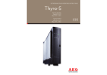
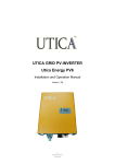
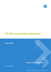
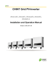
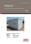
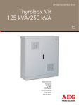
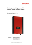
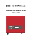
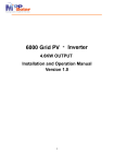
1 OPERATING INSTRUCTIONS protect pV 2000 and 2800 on-Grid solar inVerter en DOC n° 07/08/1002-2 Rev 04 2 CONTENTS Before you start Safety instructions Limited Warranty 2 4 5 1. Overview 9 2. Features 10 3. Installation instructions Opening the package Before installation Mounting Protect PV to the wall Connecting to the grid (AC utility) Connect to PV Panel (DC input) Checking 11 11 11 12 14 16 16 4. System diagram 17 5. 18 18 18 20 20 Operating your PV-Inverter Modes of operation Front panel Maximum Power Point Tracking (MPPT) Accuracy of the reading 6. Inverter status Display information LED 21 21 23 7. Communications 24 8. Trouble shooting 26 9. Specifications Electrical Typical efficiency charts vs. load 28 28 30 10. Regulation & Certificates Complicance & Standards 30 30 3 BEFORe you start Congratulations on purchasing your Protect PV 4600 Grid PV-Inverter from AEG Power Solutions GmbH referred to in this manual as “PV-Inverter”, or simply the “device”). This PV-Inverter is a highly reliable product due to its innovative design and perfect quality control. The device is dedicated to high-demand, grid-linked PV systems. This manual contains important information regarding installation and safe operation of this unit. Be sure to read this manual carefully before using your PV-Inverter. If you encounter any difficulties during installation or operation, please refer to this manual before contacting your local AEG PS dealer or representative. To obtain the latest manual and product information, please contact AEG PS. All the information included in this manual will be fully known and understood. Any mishandling and/or misuse of the product, contravening or ignoring the indications and specifications included in this manual, could lead to the cancellation of the guarantee and, more importantly, to personal damage or personal accidents. Both material and personal safety will prevail in all actions performed with the product. Should there be any doubt regarding this, please ask AEG PS. Thank you for choosing our product. Please keep this manual on hand for quick reference. 4 safety instructions risk of electric shock 1. Do not remove the casing. Protect PV® contains no user serviceable parts. Refer servicing to qualified service personnel. Both AC and DC voltage sources are terminated inside the PV-Inverter. Please disconnect these circuits before servicing. 2. When a photovoltaic panel is exposed to light, it generates a DC voltage. When connected to this equipment, a photovoltaic panel will charge the DC link capacitors. 3. Energy stored in this equipment’s DC link capacitors presents a risk of electric shock. Even after the unit is disconnected from the grid and photovoltaic panels, high voltages may still exist inside the PVInverter. Do not remove the casing until at least 30 minutes after disconnecting all power sources. 4. This unit is designed to feed power to the public power grid (utility) only. Do not connect this unit to an AC source or generator. Connecting Protect PV® to external devices could result in serious damage to your equipment. 5. Remove the unit carefully from its packaging and inspect for external damage. If you find any imperfections, please contact your local AEG PS dealer. 6. Hot surfaces Although designed to meet all safety requirements, some parts and surfaces of Protect PV are still hot during operation. To reduce the risk of injury, do not touch the heat sink at the back of the PV-Inverter or nearby surfaces while Protect PV is operating. 5 limited warranty The limited warranty provided by AEG Power Solution (“AEG PS”) in this Statement of Warranty applies only to Equipment purchased for residential, commercial or industrial use in the ordinary course of the business. terms of warranty AEG PS warrants that it is sufficiently experienced, properly qualified, registered, licensed, equipped, organized and financed to perform the Work in compliance with the terms of this Agreement. AEG PS warrants that the Equipment shall be free from defects in design, materials and workmanship for a period of sixty (60) months from the date of commissioning when AEG PS authorized service personnel performed the commissioning and start-up of the Equipment, but not longer than sixty six (66) months from the date of notification that the goods are ready for dispatch, whichever occurs first. In the event that the Equipment fails to meet the foregoing warranty, AEG PS undertakes to repair and/or replace any part found to be faulty due to errors in design or manufacture, or to be made of faulty materials if trained & authorized AEG PS personnel has conduct commissioning and start-up of the Equipment. An AEG PS Commissioning and Start-Up Service must be performed/ completed by AEG PS or by authorized service personnel. If not, the on-site Warranty will be voided and replacement of defective parts only will be covered. AEG PS shall have no liability and no obligation to repair the installed Equipment if non-authorized personnel performed the start-up and such start-up caused the Equipment to be defective. In addition, the Warranty does not cover defects originating from the materials provided by the Purchaser, a design imposed by the Purchaser, incidents brought about by contingencies or acts of God or any other cause the vendor could not reasonably be expected to foresee or whose consequences it could not prevent, repairs or replacements imposed by normal wear and tear of the equipment, damage or 6 accidents brought about by the Purchaser‘s actions, such as negligence, connection error, failure to follow instructions for maintenance, abnormal use due in particular to electrical or mechanical overload. Any parts furnished under this warranty may be new or factory-remanufactured. Repair or replacement of a defective Equipment or part thereof does not extend the original warranty period. The AEG PS reserves the rights to modify if necessary the mechanism of the equipment in order to fulfil this Agreement. warranty claims procedure Should you be experiencing technical issues with your inverters, please have your installer or reseller report the case to the country specific AEG PS hotline. AEG PS service hotline numbers are available by consulting the www.aegps.com website. To better assist you, your installer will require having the following information readily available: - Caller’s contact information - Product type and serial number - Installation date - Problem occurrence date - Problem description and error code Should the service hotline conclude to a replacement of the inverter, your installer or reseller will be required to download and complete the appropriate RMA (Return Material Authorisation). A PDF version of the RMA document can be downloaded from the www.aegps.com website. The system replacement will be facilitated by following and accepting the general terms and conditions mentioned on the second page of the RMA document. 7 exclusions AEG PS shall not be liable under the Warranty if its testing and examination discloses that the alleged defect in the Equipment does not exist or was caused by your or any third person’s misuse, negligence, improper installation or testing, unauthorized attempts to repair or modify, or any other cause beyond the range of the intended use, or by accident, fire, lightning or other hazard. There are no warranties, expressed or implied, by operation of law or otherwise, of Equipment sold, serviced or furnished under this Agreement or in connection herewith. AEG PS disclaims all implied Warranties of merchantability, satisfaction and fitness for a particular purpose. The AEG PS express warranties will not be enlarged, diminished, or affected by and no obligation or liability will arise out of AEG PS rendering technical or other advice or service in connection with the Equipment. The foregoing warranties and remedies are exclusive and in lieu of all other warranties and remedies. The warranties set forth above, constitute sole liability of AEG PS and purchaser’s exclusive remedy for any breach of such Warranties. The warranties extend only to purchasers and are not extended to any third parties. In no event shall AEG PS, its officers, directors, affiliates or employees be liable for any form of indirect, special, consequential or punitive damages arising out of the use, service or installation of the Equipment, whether such damages arise in contract or tort, irrespective of fault, negligence or strict liability or whether AEG PS has been advised in advance of the possibility of such damage. 8 Warranty extension The original factory warranty can be extended by purchasing additional Extended Warranty Program which extends factory warranty by five (5) years from the date the original factory warranty is ending and guaranty repair and/or replacement of defective parts. Travelling time, expenses and board and accommodation costs will be charged to the Purchaser. The Extended Warranty must be purchased within the first 12 months of the inverter purchase. The Extended Warranty Program does not cover failure due to commissioning or Start-Up by non-authorized personnel, improper operation or use of the equipment, lack of maintenance, alterations to original design or a change in location or operating use. Extended warranty doesn’t cover wear and tear parts such as cooling fans. The other terms of Extended Warranty Program are defined in the Terms of warranty section. 9 1. overview Protect PV 2000 & 2800 display information switch LCD display: showing the inverter status operation led, green, normal operation led, red, fault status utility (AC) connection solar panel input RS232 cover RS485 slot 10 2. features • Very high conversion efficiency (>96%) • MPPT (Maximum Power Point Tracking) • Higher power capacity than similar products of the same size. • Embedded LCD display showing complete status information • Natural convection cooling. Quiet, fan-less design • Stylish, modern casing • Compact, small profile • High reliability • Easy installation • Maintenance free • Standard RS-232, optional RS-485 and others • Embedded ENS meets VDE 0126 (1999.04), VDE 0126-1-1 • No external GFCI breaker is required 11 3. INSTALLATION INSTRUCTIONS OPENING THE PACKAGE After opening the package, please check the contents of the box. It should contain the following: 1. One Protect PV inverter 2. Instruction manual 3. One mounting frame 4. 4 mounting screws 5. 2 safety-lock screws 6. One AC socket assembly for Protect PV 2000 and 2800 BEFORE Installation Before starting installation please consider the following items: This unit is designed for indoor usage. Do not expose the unit to wet, or moist conditions. Do not expose the PV-Inverter to direct sunlight. Direct sunlight increases the internal temperature that may reduce conversion efficiency. • Check the ambient temperature of installation is within specified range of -20 ~ +55 °C. • The AC grid voltage is between 196 and 253VAC, 50/60Hz. • Electric utility company has approved the grid connection. • Qualified personnel are performing the installation. • Adequate convection space surrounds the inverter. • Inverter is being installed away from explosive vapors. • No flammable items are near the inverter. Protect PV can be installed and operated at locations where the ambient temperature is up to 55°C. However, for optimal operation, it is recommended that Protect PV is installed where the ambient temperature is between 0~40°C. 12 mounting Protect PV to the wall 1. Select a wall or solid vertical surface that can support the PV-Inverter. 2. P rotect PV requires adequate cooling space. Allow at least 20cm space above and below the inverter. 20 cm space 20 cm space 3. U sing the mounting frame as a template, drill 4 holes as illustrated in the following figures. 4. F ix the mounting frame as the figure shows. Do not drive-in the screws flush to the wall. Instead, leave 2 to 4mm exposed. 5. H ang the inverter on the mounting frame. 13 6. Check the installation conditions a) Do not install the PVInverter on a slanted surface b) Check the upper straps of PV-Inverter and ensure it fits on to the bracket c) Insert safety-lock screws to the bottom leg to secure the inverter. Check the secure mounting of the PV-Inverter by trying to raise it from the bottom. The PV-Inverter should remain firmly attached. Select the installation location so that the status display can be easily viewed. Choose a strong mounting wall to prevent vibrations while Protect PV is operating. 14 Connecting to the grid (AC utility) 1. Measure grid (utility) voltage and frequency. It should be 230VAC or 220VAC), 50/60Hz, and single phase. 2. Switch off by breaker or fuse between PV-Inverter and utility. 3. For Protect PV 2000 and 800, connect AC wires as follows: • Disassemble female socket. • Connect AC wires to connection socket as indicated. 15 • Connect Phase to pin 1, Neutral to Pin 2 and PE to Pin • Assemble the socket again and attach. • Twist the coupling ring to the PV-Inverters receptacle. Make sure it is correctly matched. To prevent risk of electric shock, ensure that PE is properly grounded before operating the PV-Inverter. 4. Suggested wire-cross section or AC wire model diameter Ø (mm) area (mm2) awG no. Protect PV 2000 1,29 1,5 16 Protect PV 2800 1,63 2,0 14 16 Connect to PV Panel (DC input) 1. Make sure the maximum open circuit voltage (Voc) of each PV string is less than 450VDC UNDER ANY CONDITION. We recommend Voc less than 360VDC with ambient temperature of 25C. 2. Use MC 3 (Multi-contact) connectors for PV array terminals. 3. Connect the positive and negative terminals from the PV panel to positive (+) terminals and negative (-) terminals on the PV-Inverter. Each DC terminal on Protect PV endorses 20ADC Before connecting PV panels to DC terminals, please make sure the polarity is correct. Incorrect polarity connection could permanently damage the unit. Check short-circuit current of the PV string. The total short-circuit current of the PV string should be less than the inverter’s maximum DC current. High voltages exist when the PV panel is exposed to the sun. To reduce risk of electric shock, avoid touching live components and treat connection terminals carefully. Checking 1. When the PV panels are connected and their output voltage is greater than 100 VDC but the AC grid is not yet connected, the message on the LCD display produce the following messages in order: “MODEL= XkW” -> “Waiting” -> “No Utility”. The display repeats “No Utility” and the RED “fault LED” turns on. 2. Close the AC breaker or fuse between PV-Inverter and grid. The normal operating sequence begins. 3. Under normal operating conditions the LCD displays “Watt=xxxx xW”. That is the power fed to the grid. The green LED turns lights-up. 4. This completes the check. 17 4. SySTEm diagRam The typical connection diagram for the entire PV system is shown in the following figure. 1. Pv-Panel: Provide DC power to Protect PV inverter 2. Protect Pv PV-inverter Converts DC (Direct Current) power from PV panel(s) to AC (Alternating Current) power. Because Protect PV is grid-connected it controls the current amplitude according to the PV Panel power supply. Protect PV always tries to convert the maximum power from your PV panel(s). 3. Connection system: This “interface” between Utility and PV-Invertermay consist of electrical breaker, fuse and connecting terminals. To comply with local safety standards and codes, the connection system should be designed and implemented by a qualified technician. 4. utility: Referred to as “grid” in this manual, is the way your electric power company provides power to your place. Please note that Protect PV can only connect to low-voltage systems (namely, 220, 230VAC, 50/60Hz). 18 5. Operating Your PV-Inverter Modes of operation There are 3 different modes of operation. 1. Normal mode: In this mode, Protect PV works normally. Whenever the supplied power from PV panel is sufficient (voltage>150VDC), Protect PV converts power to the grid as generated by the PV panel. If the power is insufficient, (voltage<120VDC) Protect PV enters a “waiting” state. Whilst “waiting” Protect PV uses just enough power from the PV panel monitor internal system status. In normal mode the green LED is on. 2. Fault mode: The internal intelligent controller can continuously monitor and adjust the system status. If Protect PV finds any unexpected conditions such as grid problems or internal failure, it will display the information on its LCD and light up the red “Fault” LED. 3. Shutdown mode: During periods of little or no sunlight, Protect PV automatically stops running. In this mode, Protect PV does not take any power from the grid. The display and LED’s on the front panel do not work. Front Panel Operating Protect PV is quite easy. During normal operation, Protect PV runs automatically. However, to achieve maximum conversion efficiency of Protect PV please read the following information: 1. Automatic ON-OFF: Protect PV starts up automatically when DC-power from the PV panel is sufficient. Once the PV-Inverter starts it enters one of the following 3 states: • Standby: The PV string can only provide just enough voltage to minimum requirements of the controller. • Waiting: When the PV string DC voltage is greater than 100V, Protect PV enters a “waiting” state and attempts to connect to the grid. 19 • Normal operation: When PV string DC voltage is greater than 150V, Protect PV operates in the normal state. In this state, it feeds power to the grid. Protect PV automatically stops when the PV power is not enough. a. Press the “Function” key repeatedly until “Contrast” shows in the display. b. Hold the “Function” key down for more than 2 seconds, until display shows “Set contrast” and a bar graph on the right. c. Press the “Function” key repeatedly until the display’s contrast is acceptable. d. Release the key for more than 10 seconds, the display will show “Watt=xxxx.xW”. 20 maximum power point trackinG (mppt) A good PV inverter must be able to convert the maximum power from any PV panel. Due to its advanced design, Protect PV PV-Inverter can track the maximum power from your PV panel in any condition. When the displayed power on the LCD output does not change dramatically, Protect PV inverter is converting the maximum power from panels. When the LCD power reading is significantly changes, Protect PV is tracking the power according to the varied sunlight. When the PV panel’s output is low, the feeding DC-power may drift slowly as does the AC power. It is because PV-Inverter is tracking maximum DC-power continuously. accuracy of the readinG The reading on the LCD is just for reference. We do not recommend using the data for checking or testing of the system. normally, its accuracy is around ±2%. In all ranges of operation, the accuracy is up to ±5%. 21 6. Inverter Status Protect PV is designed to be user-friendly; therefore, the status of the Inverter can be easily understood by reading the information shown on the front panel display. All possible messages are shown in the following table. Display information Operating conditions Message Description Power off No display PV inverter is totally shutdown, VPV <=70V Standby STANDBY 90V< Input voltage < =100V Normal Working Status Input voltage range 100~150V during start-up. After PV voltage is higher than 100V, inverter is waiting for feeding to grid When PV voltage> 150V, inverter is checking feeding conditions Inverter is feeding power. After 10 seconds of this display, LED will show wattage. Initialization & waiting READY Check grid CHECKINGxxxs Feeding grid, MPPT GRID CONNECTED FLASH FLASH FLASH-firmware Today energy Etoday=xxx.xxkWh Total energy to has been fed to grid since today Instantaneous Output power Pac=xxx.xW The real time output power in xxxx W Accumulated energy information Etot=xxxxxxkWh Total energy to has been fed to grid since inverter was installed Grid voltage Vac=xxx.xV Grid voltage in xxx.x VAC Grid frequency Fac=xx.xHz Grid frequency in xx.x Hz Monitoring parameters 22 Feeding current Iac=xx.xA PV array voltage Vdc=xxx.xV Feeding current amount in xx.x A Input voltage from PV array, xxx.x VDC System Fault Isolation failure GFCI active Grid failure Earth fault of the PV-panels or failure of surge voltage protection Leakage current on ground ERR GROUND FAULT conductor is too high Grid measured data is beyond ERR GRID the specification (voltage & frequency) ERR ISOLATION No utility1 NO GRID Utility is not available Input voltage too high SOBRETENSION DC DC OVERVOLTAGE Input voltage higher than the 450V Inverter Fault Consistent failure Temperature too high1 Output relay failure Output DC injection too high2 EEPROM problem Communication between microprocessors problem DC bus voltage is too high DC bus voltage is too low 2.5V reference voltage inside problem Output DC sensor abnormal GFCI detection abnormal The readings of 2 microprocessors are not consistent. It could be ERR MICROS caused by CPU and/or other circuits do not function well. The internal temperature is OVERTEMPERATURE higher than normal value. The relay between inverter ERR AC RELAY and grid is not functional Output DC injection HIGH DC LEVEL too high EEPROM inside has data ERR EEPROM access problem The communication between ERR COM MCU inside is abnormal The DC BUS inside is higher than HIGH DC BUS expected The DC BUS inside is lower LOW DC BUS than expected The 2.5V reference inside are ERR REF 2.5V abnormal The DC output sensor is ERR DC SENSOR abnormal The GFCI detection circuit is ERR GFCI abnormal 23 Inverter information Model display MODEL PV 4600 Inverter model, xkW inverter LCD Contrast CONTRAST The top menu of LCD contrast setting LCD contrast setting SET CONTRAST Setting the contrast of LCD LCD display lock LCD LOCKED Hold the present display message Waiting for reconnect to grid RECONNECTIONxxxs The time for reconnect to grid Firmware version FIRMWARE xx.xx F/W version information Setting Language SET LANGUAGE Set up of the display language LCD display Language LANGUAGE ENG Display Language of LCD LED There are 2 LED’s on Protect PV, one is green and the other is red. Normally, only the green LED switches on during operation. Their indicated status is explained as follows: 1. Power on (green LED): It lights to indicate that Protect PV is running. 2. Fault (red LED): Illuminates during a “fault” or “failure”. Details of possible faults and their solutions can be found in the previous table. 24 7. COmmuNiCaTiONS Protect PV is equipped with a powerful communications interface and options. Use Protect PV Monitor to monitor the status of your PV Inverter. Also, qualified personnel can upgrade the firmware using the RS232 port. 1. RS232: To use the RS232 port, remove the RS232 cover on the bottom side of Protect PV. It is a DB9 socket. The pin definition is pin 1 2 3 4 5 6 7 8 9 functional description n.C. TxD RxD n.C. Common n.C. n.C. n.C. n.C. n.C. means “no Connection” 2. Optional communications port: This port is a very powerful extension. Protect PV can accept a special card designed for the port only. The RS485 card is used to work with Protect PV logger and in multiple monitoring applications. AEG Power Solutions GmbH plan to release other communication cards in the near future. For information of card details, please refer to the user manual of each individual card. To get the latest information, please contact with your local AEG PS dealer or visit our website. 25 3. Firmware upgrade: To keep the firmware up to-date, use the RS232 port and supplied program to upgrade firmware. To do this, please contact your local AEG PS service To prevent risk of damage it is recommended that only authorized personnel perform firmware upgrades. 26 8. Trouble shooting In most situations, the Protect PV inverter requires very little service. However, if Protect PV is not able to work perfectly, please refer to the following instructions before calling your local AEG PS dealer. • Should any problems arise, the red (Fault) LED on the front panel turns on and the LCD displays the relevant information. Please refer to the following table for a list of potential problems and their solutions. DISPLAY Isolation Fault System Fault Ground I Fault Grid Fault Impedance Fault No Utility Possible actions 1. Check the impedance is between PV (+) & PV (-) and the PVInverter is earthed. The impedance must be greater than 8M 2. If the problem persists please call service 1. The ground current is too high. 2. Unplug the inputs from the PV generator and check the peripheral AC system 3. After the cause is cleared, re-plug the PV panel and check PV-Inverter status. 4. If the problem persists please call service. 1. Wait for 5 minutes, if the grid returns to normal, PV-Inverter automatically restarts. 2. Make sure grid voltage and frequency meet the specifications 3. If the problem persists please call service 1. Grid impedance higher than the permissible value. 2. Wait for 5 minutes, see if it works again. 3. Check the wires between the PV-Inverter and grid. Replace with larger wires if necessary. 4. Adjust impedance parameter by Protect PV Data program. 5. If the problem persists please call service 1. Grid is not connected. 2. Check grid connection cables. 3. Check grid usability. Inverter Failure 27 1. Check the open PV voltage, see if it is greater than or too close to 450VDC PV over Voltage 2. If PV voltage is less than 450VDC, and the problem still occurs, please call local service 1. Disconnect PV (+) or PV (-) from the input, restart the PVConsistent Fault Inverter 2. If it does not work, call service 1. The internal temperature is higher than specified normal value 2. Find a way to reduce the ambient temperature. Over Temperature 3. Or move the inverter to a cooler environment 4. If it is not effective, call local service Relay Failure DC INJ High EEPROM Failure 1. Disconnect ALL PV (+) or PV (-) 2. Wait for few seconds 3. After the LCD switches off, reconnect and check again 4. If the message reappears call your local service SCI Failure High DC Bus Low DC Bus Ref 2.5V Fault DC Sensor Fault GFCI Failure • If there is no display on the panel, please check PV-input connections. If the voltage is higher than 150V, call your local service. • During periods of little or no sunlight, the PV-Inverter may continuously start up and shut down. This is due to insufficient power generated to operate the control circuits. 28 9. Specifications MODELL Protect PV 2000 Protect PV 2800 DC INPUT Nominal DC voltage max. PV open voltage MPPT range Working range Number of MPP Tracker max. Input current 360 VDC 500 VDC 150–450 VDC 100–500 VDC 1 10 ADC 360 VDC 500 VDC 150–450 VDC 100–500 VDC 1 13 ADC 2000 W 2200 W 184–264,5 VAC 50 Hz <3% ~1 2800 W 3000 W 184–264,5 VAC 50 Hz <3% ~1 LCD Display 1 line, 16 Char. > 96 % > 95 % IP 43 –20 °C ~ 55 °C 0 ~ 95 % non-condensing ~7W < 35 dBA Standard: RS232 Optional: RS485 and others LCD Display 1 line, 16 Char. > 96 % > 95 % IP 43 –20 °C ~ 55 °C 0 ~ 95 % non-condensing ~7W < 35 dBA Standard: RS232 Optional: RS485 and others 350 x 302 x 124 12,25 350 x 302 x 139 12,5 aC OUTPUT Output power max. power Operational voltage Operational frequency Current distorsion Power factor (cos ϕ) system Display Max. efficiency Euro efficiency Protection degree Operation temp. Humidity Standby power Acoustic noise level Comm. Interface mechanical W x D x H (mm) Weight (kg) Product specifications are subject to change without notice Hinweis: Aufgrund von Toleranzen der Testgeräte, Umgebungsbedingungen und Modellspezifikationen können tatsächliche Ergebnisse abweichen. 29 Typical Efficiency charts vs. Load 30 10. Regulation & Certificates Compliance & Standards EMC: DIN EN 50081, part 1 (EMV-interference emission) (EN 55014, EN 60555 part 2, EN 55011 group 1, class B) DIN EN 50082, part 1 (EMV-interference immunity) GRID INTERFACE: DIN EN 61000-3-2 GRID MONITORING: EN DIN VDE 0126 (1999.04), VDE 0126-1-1:2006-02 LOW VOLTAGE REGULATION: DIN EN 50178 (4.98) (VDE 0160, IEC62103) DIN EN 60146, Teil 1-1 (3.94) (VDE 0558, Teil 11) The certificates regarding compliance of the Protect PV 2000 and PV2800 inverter with: VDE standards, RD 1663/2000, EC markings or other international standards will be issued upon request. Incident Form In order to provide a better and faster client assistance service in the case of an incident, please fill in the form on the service sheet and guarantee attached to this with the information requested. This form will be filled in by a technician who is responsible for the installation of the solar plant and sent to the AEG PS for this to be registered to then deal with the incident. As many copies as are necessary may be made of this form in order to inform on different incidents that may affect each individual inverter. 31 32 OPERATING INSTRUCTIONS EN, 07/12 - V1 - 8000022287 AEG is a registered trademark used under license from AB Electrolux AEG Power Solutions GmbH Emil-Siepmann-Str. 32 59581 Warstein-Belecke - Germany Tel.: +49 (0) 2902 763-520/-290 - Fax: +49 (0) 2902 763-1201 www.aegpowercontrollers.com - www.aegps.com