1
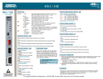
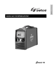
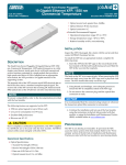
JOBAID
U-BR1TE
U-BR1TE
CLEI: SIC2XY0K _ _
4 Monitor Status LED for operational status.
DESCRIPTION
The U-BR1TE is a line card that plugs into a single channel slot of a Total Access
750/850/1500 channel bank. It provides an ISDN U-interface and allows the
transport of Basic Rate 2B+D information over T1 carriers. The U-BR1TE features:
■
■
■
■
61180020L1-22A
0004
STATUS LEDS
Status
18kft nominal range in mixed gauge wire
ISDN 2B1Q interface
Internal testing of individual B channels
All Layer 1 maintenance functions
SW1-6
AP
SW1-5
(D)
*ON
OFF
ON
ON
OFF
OFF
ON
* Factory Default
C A U T I O N !
SUBJECT TO ELECTROSTATIC DAMAGE
OR DECREASE IN RELIABILITY.
HANDLING PRECAUTIONS REQUIRED.
●
GREEN
●
YELLOW
✷✷
REM
SW SETTINGS
SW1-3
SW1-4
SW1-5
RED
✷
can also be accomplished through BCU/SCU craft interface. Refer to BCU/SCU
Installation and Maintenance practice or Job Aid. Make changes to SW1 options
as necessary.
SW1-2
●
✷✷
the TA 750/850/1500 U-BR1TE card and inspect for damage. If damage is
1 Unpack
apparent, refer to your carrier or supplier for remedy.
SW1 is provisioned properly for your application. Refer to the table in this
2 Verify
job aid for default provisioning and other provisioning options. Provisioning
Label
Function/Description
LULT/LUNT Termination Mode
*ON…LULT Mode (RT Typical)
OFF…LUNT Mode (COT Typical)
SX
Sealing Current
*ON…DC sealing current provided
OFF…DC sealing current not provided
B1
Service Level Station
B2
D
Service
SW1-3
SW1-4
Option
(B1)
(B2)
2B+D
*ON
*ON
2B
ON
ON
B1+D
ON
OFF
B2+D
OFF
ON
B1
ON
OFF
B2
OFF
ON
D
OFF
OFF
ZBS
Zero Byte Substitution
ON....Enable ZBS
*OFF…Disable ZBS
OFF
✷
TURN UP STEPS
Switch
SW1-1
●
●
GREEN
Pushbutton
Indicates both loop and carrier synchronization have been
established
Solid indicates neither loop nor carrier synchronization has
been established.
Flashing once every two seconds indicates loop synchronization has been established, but carrier synchronization
has not.
Flashing twice every second indicates carrier synchronization has been established, but loop synchronization has
not.
Indicates that Layer 1 is established from the ISDN switch
to the customer ISDN terminal equipment.
Solid when a front panel test has been initiated or when
responding to 2B+D loopback request.
Flashes once every two seconds when responding to a B1
loopback request.
Flashes twice every two seconds when responding to B2
loopback request.
Indicates the unit has been provisioned by the BCU/SCU.
Alternative provisioning switch. Changes provisioning
source from remote to manual.
5
Provisioning - The TA 750/850/1500 supports two types of provisioning
modes, local and remote. Local provisioning results in the unit operating
as defined by the on board switches. Remote provisioning, if chosen,
results in the unit operating as defined by the system controller menu settings (on-board switches are ignored). The operational mode is indicated
by the REM LED and can be changed by activating the AP (Alternate
Provisioning) faceplate switch
6
Connect VT 100 compatible terminal to BCU/SCU faceplate ADMIN port.
The ADMIN port issued for provisioning, testing, and performance monitoring functions.
7a. Connect DB9 cable
7b. Run terminal emulation program
7c. If using Windows Hyperterminal, open by selecting
Programs/Accessories/Hyperterminal
7d. Login and navigate through ADMIN port menu structure
Note: To ensure proper display background, select VT 100 Terminal Emulation
under settings.
U-BR1TE card into a TA 750 chassis slot 1-6, TA 850 chassis slot 1-6, or TA
3 Insert
1500 chassis slot 1-24. To insert, hold the U-BR1TE card by the faceplate while
supporting the bottom edge of the card. Align the card edge with the guide
groove in the TA 750/850/1500 chassis. Insert into chassis until the edge card conector seats firmly into the chassis backplane. Lock the unit in place by pushing
in on the locking lever.
■ For a complete Installation and Maintenance Practice: 877.457.5007, Document 442.
For the TA1500 Chassis Job Aid: 877.457.5007, Document 445.
Please have your fax number available.■
U-BR1TE
7 Navigate through menus to perform desired function.
PRICING AND AVAILABILITY 800.827.0807
TECHNICAL SUPPORT 800.726.8663
RETURN FOR REPAIR 256.963.8722
www.adtran.com
MLT3.0/ISDN CHANNEL TEST (TA 1500 ONLY)
Note: To traverse through the menus, select the desired entry and press Enter. To work backwards in
the menu, press ESC (escape key).
– Test functions can be activated through front panel Bantam jacks, the ADMIN port, or
8 Testing
inband loopback sequences.
TESTING
■ Loopback tests – initiated from either the ISDN switch or the faceplate via the local craft interface
in the Network-to-Customer direction.
■ Point-to-point test – initiated via the local craft interface toward either the U-interface or the T1
carrier interface.
■ Local Loopback – initiated from the local craft interface for either bearer channel.
■ Leased Mode Testing – responds to independent network-issued OCU and CSU latching loop-
back sequences for B1 and B2, when configured Adjacent-to-Customer and the D channel is disabled.
CONNECTIONS
■ All connections are made through the 50-pin amphenol connector on the back panel TA
Channel Test (LUNT Mode)
Upon detection of the Test Initiative Voltage (116Vdc behind 8kΩ applied to Tip with Ring open)
the LUNT does the following:
■ The channel unit sends a Channel Test mp-eoc message downstream to the LULT, signaling
the request for a MLT channel test.
■ The channel unit notifies the BCU/SCU that a MLT test is underway.
■ The unit sends a 333.3 Hz tone between the tip and ring leads. This tone is compliant with
TR-TSY-OO465.
■ When the Test Initiative Voltage is removed, the active test status indication to the BCU/SCU is
removed, a Return to Normal mp-eoc message is sent to the LULT, and the U-Interface
attempts re-synchronization.
Channel Test (LULT Mode)
Upon receipt of the Channel Test mp-eoc message, the LULT does the following:
■ The channel unit notifies the BCU/SCU that a MLT test is underway.
■ The LULT connects the bypass pair. This connects the customer drop to the common
equipment through TEST_R and TEST_T. The set-up sequence is complete.
■ Upon completion of the automatic test the bypass relay de-energizes.
■ The channel unit then attempts to re-synchronize the U-interface between the LULT and the
NT1
BANTAM TEST JACKS
750/850/1500.
■ Accommodate DS0 Logic Testers such as the TPI 108/109 RT II to perform upstream and down
stream testing.
APPLICATIONS
TELECOMMUNICATIONS CODES
This product is intended to be installed in products providing a Type “B” or “E” enclosure, and
in a Restricted Access Location.
CUSTOMER
NT1
TOTAL ACCESS 1500/750
2-Wire
T Carrier
HD-10 BRI Mux HD-10 BRI Mux HD-10 BRI Mux HD-10 BRI Mux HD-10 BRI Mux
QFC-C QFC-C QFC-C QFC-C
1181200L1
1181200L1
1181200L1
1181200L1
POWER
POWER
DSX
DSX
LBK
LBK
1181200L1
1181300L1
1181300L1
PWR
LBK
PWR
1181300L1
PWR
DSX
#1
DSX
#1
#2
DSX
#2
DSX
#2
DSX
#2
#3
DSX
#3
DSX
#3
DSX
#3
#4
DSX
#4
DSX
#4
DSX
#4
DSX
#1
1181310L1
TST
TST
TST
TST
ALM
ALM
ALM
ALM
R
X
6V
–
R
X
6V
–
HTU-C
1181101L1
R
X
6V
–
R
X
1181101L1
HTU-C
1181101L1
HTU-C
1181101L1
PWR
DSX
HTU-C
1181101L1
PWR
DSX
TST
LP1
1181101L1
PWR
DSX
TST
LP1
HD-10 BRI Mux HD-10 BRI Mux HD-10 BRI Mux HD-10 BRI Mux HD-10 BRI Mux
QFC-C QFC-C QFC-C QFC-C
1181200L1
HTU-C
PWR
TST
LP1
T
X
HTU-C
DSX
TST
+
T
X
PWR
DSX
ALM
+
T
X
PWR
LP
ALM
+
T
X
LBK
LP
ALM
+
DSX
LBK
LP
ALM
PWR
DSX
LBK
LP
1181310L1
PWR
DSX
LBK
–
1181310L1
PWR
DSX
6V
T1-OR T1-OR
1181310L1
PWR
#1
DSX
DSX
T1-OR T1-OR
1181300L1
PWR
DSX
DSX
TOTAL ACCESS 1500/750
DSX
TST
LP1
TST
LP1
LP1
HTU-C
1181101L1
PWR
DSX
TST
LP1
HTU-C
1181101L1
PWR
DSX
TST
LP1
HTU-C
1181101L1
PWR
DSX
TST
LP1
HTU-C
1181101L1
PWR
DSX
TST
LP1
HTU-C
1181101L1
PWR
DSX
TST
LP1
HTU-C
1181101L1
PWR
DSX
TST
LP1
HTU-C
1181101L1
PWR
DSX
TST
LP1
1181200L1
HTU-C
1181200L1
POWER
DSX
DSX
LBK
LBK
DSX
1181200L1
LBK
LP1
1181300L1
PWR
TST
1181300L1
PWR
DSX
#1
DSX
#2
DSX
#3
DSX
#4
DSX
1181300L1
PWR
#1
DSX
#2
DSX
#3
DSX
#4
1181300L1
#1
DSX
#1
DSX
#2
DSX
#2
#3
DSX
#3
#4
DSX
#4
LP2
LP2
LP2
LP2
LP2
LP2
LP2
LP2
LP2
LP2
LP2
LP2
TST
TST
ALM
TST
ALM
TST
ALM
ALM
ALM
ALM
ALM
ALM
ALM
ALM
ALM
ALM
ALM
ALM
ALM
ALM
T1-OR T1-OR
1181310L1
PWR
PWR
DSX
DSX
DSX
LP2
ALM
1181310L1
PWR
DSX
R
X
6V
–
R
X
6V
–
R
X
6V
–
1181101L1
DSX
TST
LP1
+
T
X
HTU-C
PWR
ALM
+
T
X
1181310L1
PWR
LP
ALM
+
T
X
LBK
LP
ALM
+
DSX
LBK
LP
ALM
1181310L1
DSX
LBK
LP
T1-OR T1-OR
PWR
DSX
LBK
6V
–
T
R
X
X
HTU-C
1181101L1
PWR
HTU-C
1181101L1
PWR
DSX
1181101L1
DSX
TST
LP1
HTU-C
PWR
DSX
TST
TST
LP1
LP1
HTU-C
1181101L1
PWR
HTU-C
HTU-C
1181101L1
PWR
DSX
TST
LP1
1181101L1
DSX
TST
LP1
2-Wire
HTU-C
PWR
DSX
TST
LP1
1181101L1
PWR
DSX
TST
LP1
HTU-C
1181101L1
PWR
DSX
TST
LP1
HTU-C
1181101L1
PWR
DSX
TST
LP1
HTU-C
1181101L1
PWR
DSX
TST
LP1
HTU-C
1181101L1
PWR
DSX
TST
LP1
HTU-C
1181101L1
PWR
DSX
TST
HTU-C
1181101L1
PWR
DSX
TST
LP1
LP1
LP2
LP2
LP2
LP2
LP2
LP2
LP2
LP2
LP2
LP2
LP2
ALM
LP2
ALM
LP2
ALM
LP2
ALM
ALM
ALM
ALM
ALM
ALM
ALM
ALM
ALM
ALM
ALM
LUNT
LUNT
TOTAL ACCESS 1500/750
HD-10 BRI Mux HD-10 BRI Mux HD-10 BRI Mux HD-10 BRI Mux HD-10 BRI Mux
QFC-C QFC-C QFC-C QFC-C
1181200L1
T Carrier
TOTAL ACCESS 1500/750
HD-10 BRI Mux HD-10 BRI Mux HD-10 BRI Mux HD-10 BRI Mux HD-10 BRI Mux
QFC-C QFC-C QFC-C QFC-C
T1-OR T1-OR
T1-OR T1-OR
PWR
PWR
PWR
PWR
PWR
POWER
PWR
PWR
POWER
DSX
#1
PWR
DSX
#1
#1
#1
DSX
PWR
DSX
DSX
PWR
DSX
DSX
PWR
DSX
PWR
PWR
PWR
PWR
PWR
DSX
PWR
DSX
PWR
DSX
DSX
#2
DSX
DSX
DSX
DSX
#2
#2
#2
LBK
DSX
DSX
LBK
DSX
DSX
LBK
DSX
LBK
DSX
DSX
DSX
DSX
DSX
TST
DSX
TST
DSX
LBK
TST
#3
TST
LBK
DSX
DSX
#3
#3
#3
LP
TST
DSX
LP
TST
DSX
LP
TST
LP
TST
TST
TST
TST
LP1
TST
LP1
TST
LP1
TST
LP1
#4
DSX
DSX
DSX
ALM
LP1
#4
ALM
LP1
#4
ALM
LP1
#4
ALM
LP1
LP1
LP1
LP1
LP1
LP1
LP1
1181300L1
PWR
LBK
DSX
1181300L1
PWR
1181300L1
PWR
1181300L1
PWR
TST
TST
TST
TST
ALM
ALM
ALM
ALM
1181310L1
+
6V
–
1181310L1
+
T
X
R
X
6V
–
1181310L1
+
T
X
R
X
6V
–
1181310L1
+
T
X
R
X
6V
T
X
R
X
HTU-C
1181101L1
HTU-C
1181101L1
HTU-C
1181101L1
HTU-C
1181101L1
HTU-C
1181101L1
HTU-C
1181101L1
HTU-C
1181101L1
HTU-C
1181101L1
HTU-C
1181101L1
HTU-C
1181101L1
HTU-C
1181101L1
HTU-C
1181101L1
HTU-C
1181101L1
HTU-C
1181101L1
LP2
LP2
LP2
LP2
LP2
LP2
LP2
LP2
LP2
LP2
LP2
ALM
LP2
ALM
LP2
ALM
LP2
ALM
ALM
ALM
ALM
ALM
ALM
ALM
ALM
ALM
ALM
ALM
1181200L1
1181200L1
1181200L1
1181200L1
T1-OR T1-OR
T1-OR T1-OR
PWR
PWR
PWR
PWR
PWR
PWR
PWR
DSX
#1
PWR
DSX
#1
#1
#1
DSX
PWR
DSX
DSX
PWR
DSX
DSX
PWR
DSX
PWR
PWR
PWR
PWR
PWR
DSX
PWR
DSX
PWR
DSX
DSX
#2
DSX
DSX
#2
#2
#2
LBK
DSX
DSX
LBK
DSX
DSX
LBK
DSX
LBK
DSX
DSX
DSX
DSX
DSX
TST
DSX
TST
DSX
TST
DSX
#3
TST
DSX
#3
#3
#3
LP
TST
DSX
LP
TST
DSX
LP
TST
LP
TST
TST
TST
TST
LP1
TST
LP1
TST
LP1
TST
LP1
LP1
LP1
LP1
LP1
LP1
LP1
1181200L1
1181300L1
PWR
LBK
DSX
#4
DSX
1181300L1
PWR
#4
DSX
1181300L1
PWR
#4
DSX
TST
TST
TST
TST
ALM
ALM
ALM
ALM
–
#4
1181310L1
ALM
ALM
+
6V
–
1181310L1
ALM
+
T
X
R
X
6V
–
1181310L1
ALM
+
T
X
R
X
6V
–
1181310L1
+
T
X
R
X
6V
T
X
R
X
HTU-C
1181101L1
HTU-C
1181101L1
HTU-C
1181101L1
HTU-C
1181101L1
HTU-C
1181101L1
HTU-C
1181101L1
HTU-C
1181101L1
HTU-C
1181101L1
HTU-C
1181101L1
HTU-C
1181101L1
HTU-C
1181101L1
LP1
HTU-C
1181101L1
LP1
HTU-C
1181101L1
LP1
HTU-C
1181101L1
2-Wire
HD-10 BRI Mux HD-10 BRI Mux HD-10 BRI Mux HD-10 BRI Mux HD-10 BRI Mux
QFC-C QFC-C QFC-C QFC-C
1181200L1
1181200L1
1181200L1
1181200L1
POWER
POWER
DSX
DSX
LBK
LBK
1181200L1
1181300L1
PWR
LBK
LP2
LP2
LP2
LP2
LP2
LP2
LP2
LP2
LP2
LP2
LP2
ALM
LP2
ALM
LP2
ALM
ALM
ALM
ALM
ALM
ALM
ALM
ALM
ALM
ALM
ALM
1181300L1
1181300L1
T1-OR T1-OR
1181310L1
1181310L1
T1-OR T1-OR
1181310L1
1181310L1
HTU-C
1181101L1
HTU-C
1181101L1
HTU-C
1181101L1
HTU-C
1181101L1
HTU-C
1181101L1
HTU-C
1181101L1
HTU-C
1181101L1
HTU-C
1181101L1
HTU-C
1181101L1
HTU-C
HTU-C
HTU-C
HTU-C
HTU-C
T Carrier
HD-10 BRI Mux HD-10 BRI Mux HD-10 BRI Mux HD-10 BRI Mux HD-10 BRI Mux
QFC-C QFC-C QFC-C QFC-C
1181200L1
1181200L1
1181200L1
1181200L1
POWER
POWER
DSX
DSX
LBK
LBK
1181200L1
1181300L1
PWR
1181300L1
PWR
1181300L1
1181300L1
PWR
PWR
PWR
PWR
PWR
PWR
PWR
#1
PWR
DSX
#1
#1
#1
DSX
PWR
DSX
DSX
PWR
DSX
DSX
PWR
DSX
PWR
PWR
PWR
PWR
PWR
DSX
PWR
DSX
PWR
DSX
DSX
#2
DSX
DSX
#2
#2
#2
LBK
DSX
DSX
LBK
DSX
DSX
LBK
DSX
LBK
DSX
DSX
DSX
DSX
DSX
TST
DSX
TST
DSX
TST
#3
TST
DSX
#3
#3
#3
LP
TST
DSX
LP
TST
DSX
LP
TST
LP
TST
TST
TST
TST
LP1
TST
LP1
TST
LP1
TST
LP1
#4
DSX
DSX
DSX
ALM
LP1
#4
ALM
LP1
#4
ALM
LP1
#4
ALM
LP1
LP1
LP1
LP1
LP1
LP2
LP1
LP2
LP1
LP2
LP2
LP2
LP2
LP2
LP2
LP2
LP2
LP2
LP2
LP2
LP2
TST
TST
TST
TST
ALM
ALM
ALM
ALM
ALM
ALM
ALM
ALM
ALM
ALM
ALM
ALM
DSX
PWR
PWR
TST
TST
TST
TST
ALM
ALM
ALM
ALM
LP1
LP2
ALM
1181300L1
PWR
DSX
DSX
+
6V
–
+
T
X
R
X
6V
–
+
T
X
R
X
6V
–
ALM
+
T
X
R
X
6V
T
X
R
X
ALM
ALM
ALM
ALM
ALM
1181101L1
1181101L1
1181101L1
1181101L1
1181101L1
LBK
T1-OR T1-OR
1181310L1
T1-OR T1-OR
1181310L1
1181310L1
HTU-C
1181101L1
HTU-C
1181101L1
HTU-C
1181101L1
HTU-C
1181101L1
HTU-C
1181101L1
HTU-C
1181101L1
HTU-C
1181101L1
HTU-C
1181101L1
HTU-C
1181101L1
HTU-C
HTU-C
HTU-C
HTU-C
HTU-C
PWR
PWR
PWR
PWR
PWR
PWR
#1
PWR
DSX
#1
#1
#1
DSX
PWR
DSX
DSX
PWR
DSX
DSX
PWR
DSX
PWR
PWR
PWR
PWR
PWR
DSX
PWR
DSX
PWR
DSX
DSX
#2
DSX
DSX
#2
#2
#2
LBK
DSX
DSX
LBK
DSX
DSX
LBK
DSX
LBK
DSX
DSX
DSX
DSX
DSX
TST
DSX
TST
DSX
TST
#3
TST
DSX
#3
#3
#3
LP
TST
DSX
LP
TST
DSX
LP
TST
LP
TST
TST
TST
TST
LP1
TST
LP1
TST
LP1
TST
LP1
#4
DSX
DSX
DSX
ALM
LP1
#4
ALM
LP1
#4
ALM
LP1
#4
ALM
LP1
LP1
LP1
LP1
LP1
LP2
LP1
LP2
LP1
LP2
LP2
LP2
LP2
LP2
LP2
LP2
LP2
LP2
LP2
LP2
LP2
ALM
ALM
ALM
ALM
ALM
ALM
ALM
ALM
ALM
DSX
PWR
PWR
+
6V
–
–
1181310L1
PWR
DSX
DSX
OUTPUT
C
A
C
X
-
+
T
X
R
X
6V
–
+
T
X
R
X
6V
–
ALM
+
T
X
R
X
6V
T
X
R
X
ALM
ALM
ALM
ALM
1181101L1
1181101L1
1181101L1
1181101L1
1181101L1
2-Wire
Changes or modifications not expressly approved by ADTRAN could void the user’s authority to
operate this equipment.
–
–
Tandem
Office (Sink)
Adjacent to
Custome
LULT
SX
B1
B2
D
ZB5
Tandem Office
(Source)/U-Repeater
LUNT
Adjacent to
Switch
1181300L1
PWR
LULT
SX
B1
B2
D
ZB5
LBK
LUNT
DSX
LBK
LULT
SX
B1
B2
D
ZB5
1181200L1
POWER
DSX
LUNT
1181200L1
POWER
TOTAL ACCESS 1500/750
LULT
SX
B1
B2
D
ZB5
1181200L1
TOTAL ACCESS 1500/750
LUNT
1181200L1
INPUT
PC
TC
IC
This device complies with Part 15 of the FCC rules. Operation is subject to the following two
conditions: (1) This device may not cause harmful interference, and (2) this device must accept
any interference received, including interference that may cause undesired operation.
CUSTOMER
NT1
2-Wire
CODE
LULT
SX
B1
B2
D
ZB5
Adjacent to
Customer
LULT
SX
B1
B2
D
ZB5
Adjacent to
Switch
ISDN
SWITCH
1181200L1
POWER
1181101L1
PWR
LP2
ALM
WARRANTY
Warranty for Carrier Network products manufactured by ADTRAN and supplied under Buyer’s
order for use in the U.S. is ten (10) years. For a complete copy of ADTRAN’s U.S. Carrier
Network Equipment Warranty: (887) 457-5007, Document 414.