1
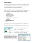
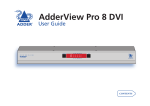
Warranty
Adder Technology Limited,
Technology House,
Trafalgar Way, Bar Hill,
Cambridge, CB3 8SQ,
United Kingdom
Tel: +44 (0)1954 780044
Fax: +44 (0)1954 780081
Adder Corporation,
29 Water Street,
Newburyport, MA 01950,
United States of America
Adder Asia Pacific
6 New Industrial Road,
Hoe Huat Industrial Building
#07-01, Singapore 536199
Tel: +1-888-932-3337
Fax: +1-888-275-1117
Tel: +65 6288 5767
Fax: +65 6284 1150
Email: [email protected]
Web: www.adder.com
© 2008 Adder Technology Limited • Release 1.0e • January 2008 • Part No. ADD0074
All trademarks are acknowledged. Documentation by Corporate Text & Design (www.ctxd.com)
R
O
IT
N
O
M
Black connector
(to monitor)
R
E
T
U
P
O
M
ls
C
na
ig
os
e
Vid S
CL
O
NE
U
AT
ST
Control button
and indicator
What’s in the box
t
os
Gh
C
DD
T
E
R
A
VG
U
This equipment generates, uses and can radiate
radio frequency energy and if not installed and
used properly, that is, in strict accordance with the
manufacturer’s instructions, may cause interference to
radio communications. It has been tested and found to
comply with the limits for a Class A computing device in
accordance with the specifications in Subpart J of part 15
of FCC rules, which are designed to provide reasonable
protection such interference when the equipment is
operated in a commercial environment. Operation of this
equipment in a residential area may cause interference, in
which case the user at his own expense will be required
to take whatever measures may be necessary to correct
the interference. Changes or modifications not expressly
approved by the manufacturer could void the user’s
authority to operate the equipment.
This equipment has been tested and found to
comply with the limits for a class B computing
device in accordance with the specifications
in the European standard EN55022. These
limits are designed to provide reasonable protection against
harmful interference. This equipment generates, uses and
can radiate radio frequency energy and if not installed and
used in accordance with the instructions may cause harmful
interference to radio or television reception. However, there
is no guarantee that harmful interference will not occur
in a particular installation. If this equipment does cause
interference to radio or television reception, which can
be determined by turning the equipment on and off, the
user is encouraged to correct the interference with one or
more of the following measures: (a) Reorient or relocate
the receiving antenna. (b) Increase the separation between
the equipment and the receiver. (c) Connect the equipment
to an outlet on a circuit different from that to which
the receiver is connected. (d) Consult the supplier or an
experienced radio/TV technician for help.
C
DD
P
FCC statement
European EMC directive
89/336/EEC
The Extended Display Identification Data
(EDID) information stored within the DDC
Ghost can either be cloned from a monitor
or used with a standard set of information
(see Standard EDID Information).
ta
da
GA
tV
os
Gh
I
ED
M
• If you use a power extension cable with
the optional power adapter, make sure the
total ampere rating of the devices plugged
into the extension cable do not exceed
either the cable’s ampere rating or that of
the wall outlet.
D
Blue connector
(to computer)
O
• Replace the power adapter with a
manufacturer approved type only.
Optional
power
input
C
• Do not use the power adapter if the
power adapter case becomes damaged,
cracked or broken or if you suspect that it
is not operating properly.
The DDC Ghost module is designed to
attach in-line with a VGA connection
in order to present Extended Display
Identification Data (EDID) to the video
controller independently of the actual
monitor, switch or extender unit. Video
signals are passed straight through the
DDC Ghost.
CL
ON
E
R
• No user serviceable parts are contained
within the module or the power adapter
- do not dismantle.
User Guide
O
IT
• Warning – the optional power adapter
contains live parts.
DDC Ghost
N
• Not suitable for use in hazardous or
explosive environments or next to highly
flammable materials.
Adder Technology Ltd warrants that this
product shall be free from defects in
workmanship and materials for a period of
two years from the date of original purchase.
If the product should fail to operate correctly
in normal use during the warranty period,
Adder will replace or repair it free of charge.
No liability can be accepted for damage due
to misuse or circumstances outside Adder’s
control. Also Adder will not be responsible
for any loss, damage or injury arising directly
or indirectly from the use of this product.
Adder’s total liability under the terms of this
warranty shall in all circumstances be limited
to the replacement value of this product. If
any difficulty is experienced in the installation
or use of this product that you are unable to
resolve, please contact your supplier.
O
• For use in dry, oil free indoor environments.
M
Safety information
S
S
TU
TA
DDC Ghost module
Video cable
(15 pin D-type male
to 15 pin D-type
male)
What you may additionally need
Mains to 5VDC power adapter (if power cannot be obtained
from the controlling computer via the video cable)
Adder P/N: PSU-IEC-5VDC
Additional video cable (15 pin D-type male to 15 pin D-type male) Adder P/N: VSC18
C
DD
Link the monitor
to the BLACK
connector
P
T
U
E
R
Installing for normal operation
M
GA
tV
os
Gh
O
C
A
CL
R
O
IT
N
O
The DDC Ghost module contains a default set of EDID values which
may be used immediately with most monitors (see Standard EDID
Information). Alternatively, you can use a ‘donor’ monitor from which
you can clone new EDID information.
M
Cloning EDID information
ON
E
US
AT
ST
To install for normal operation
To clone EDID information
1 Link the BLACK connector of the DDC Ghost to the monitor
(diagram A).
1 Link the BLACK connector of the DDC Ghost to the donor monitor
(diagram A).
2 Link the BLUE connector of the DDC Ghost to the computer
video output (diagram B)
2 Provide power for the DDC Ghost module in one of two ways, either:
Note: In operation, the red STATUS indicator should be on. If
it is not then power is not being correctly supplied from the
computer (pin 9 of the VGA connector). If this situation cannot
be resolved, attach the optional 5VDC power adapter to the
socket on the side of the DDC Ghost module (diagram C).
• Link the BLUE connector of the DDC Ghost to a computer video
output for the duration of the cloning operation (diagram B), or
• Attach the optional 5VDC power adapter to the socket on the side
of the DDC Ghost module (diagram C).
B
OR
NIT
3 Switch on the computer and monitor in the normal manner.
t
s
o
h
G
MO
C
D
D
3 Ensure that the donor monitor and the DDC Ghost module are
powered. The DDC Ghost red STATUS indicator should be on.
V
A
G
S
U
T
TA
S
4 Using a narrow implement, press and hold the recessed button
labelled CLONE on the side of the module (diagram D). The STATUS
indicator will begin to flash slowly for five seconds. Release the
button while the indicator is still slowly flashing.
E
N
O
L
C
CO
MP
UT
ER
Link the computer
to the BLUE
connector
• If new EDID information is available, it will be copied to the DDC
Ghost module memory.
• If there is an error during cloning then the DDC Ghost will be
automatically reset to its standard values.
C
US
AT
ST
O
M
R
O
IT
N
C
DD
CL
GA
tV
os
Gh
ON
E
R
E
T
U
P
M
O
C
Resetting EDID information
If required, you can reinstate the standard EDID values (see Standard
EDID Information) into the DDC Ghost module memory.
If power is
unavailable from
the computer via the
BLUE connector, use
the optional 5VDC
power adapter
ID Manufacturer Name:
Product ID Code:
Last 5 Digits of Serial Number:
Week of Manufacture:
Year of Manufacture:
Complete Serial Number:
NON
0000
00000
00
1990
0000000000
Video input definition
Analog Signal:
Separate Syncs
0.700, 0.300 (1.000 Vp-p)
720 X 400 @ 70Hz (IBM,VGA)
640 X 480 @ 60Hz (IBM,VGA)
640 X 480 @ 75Hz (VESA)
800 X 600 @ 60Hz (VESA)
O
IT
N
O
M
E
T
U
P
M
O
CL
R
C
DD
GA
tV
os
Gh
C
D
R
1 Ensure that the DDC Ghost is powered (either from the video output
of a host computer or an optional power adapter) and check that the
red STATUS indicator is on.
3 Release the button while the red STATUS indicator is off, following
the five slow flashes. The reset operation will take place and then
the red STATUS indicator will flash rapidly five times to indicate a
successful completion.
The standard EDID information supplied within the DDC
Ghost module represents a standard analogue monitor
(with no manufacturer details) capable of resolutions up to
1600x1200@60Hz. Other presented information is as follows:
Established timing I
To reset the EDID information
2 Using a narrow implement, press and hold the recessed button
labelled CLONE on the side of the module (diagram D). The red
STATUS indicator will flash slowly for five seconds and then will go
off for a further five seconds.
Standard EDID information
Manufacturer details
• If there is no EDID information to clone then the existing DDC
Ghost memory will be not altered.
5 When the operation is complete, the STATUS indicator will flash
rapidly five times. Disconnect the DDC Ghost module from the donor
monitor.
During normal operation, the DDC Ghost module supplies either
standardised or cloned EDID information to the computer instead of
the data from the connected monitor.
US
AT
ST
ON
E
Press and hold the
recessed CLONE button.
Release it as follows:
To clone: While
indicator is slowly
flashing.
To reset: While
indicator is off
(immediately following
the slow flashes).
Established timing II
800 X 600 @ 75Hz (VESA)
1024 X 768 @ 60Hz (VESA)
1024 X 768 @ 75Hz (VESA)
1280 X 1024 @ 75Hz (VESA)
Standard timing identification
1280 X 1024 @60Hz
1600 X 1200 @60Hz
1152 X 864 @75Hz
Note: The DDC
Ghost module has
the capacity to store
one standard EDID
data block plus one
extension block.