1
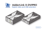
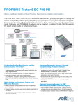
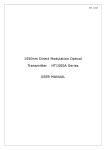
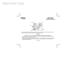
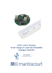
Warranty
Adder Technology Ltd warrants that this product shall be free from defects in workmanship and
materials for a period of two years from the date of original purchase. If the product should fail to
operate correctly in normal use during the warranty period, Adder will replace or repair it free of
charge. No liability can be accepted for damage due to misuse or circumstances outside Adder’s
control. Also, Adder will not be responsible for any loss, damage or injury arising directly or indirectly from the use of this product. Adder’s total liability under the terms of this warranty shall in
all circumstances be limited to the replacement value of this product.
AdderLink LPV
User Guide
Regulatory information
Your AdderLink LPV package
European EMC directive 89/336/EEC
This equipment has been tested and found to comply with the limits for a class A
computing device in accordance with the specifications in the European standard
EN55022. These limits are designed to provide reasonable protection against harmful
interference. This equipment generates, uses and can radiate radio frequency energy and if not
installed and used in accordance with the instructions may cause harmful interference to radio or
television reception. However, there is no guarantee that harmful interference will not occur in a
particular installation. If this equipment does cause interference to radio or television reception,
which can be determined by turning the equipment on and off, the user is encouraged to correct
the interference with one or more of the following measures: (a) Reorient or relocate the receiving antenna. (b) Increase the separation between the equipment and the receiver. (c) Connect
the equipment to an outlet on a circuit different from that to which the receiver is connected. (d)
Consult the supplier or an experienced radio/TV technician for help.
The AdderLink LPV allows you to extend analogue video over a maximum of 150 metres of
twisted pair cable with the minimum of infrastructure and fuss. It is simply powered via USB from
the transmitter end, so that no additional power supply is required at the receiver, hence the
name LPV or Line Powered Video.
In addition to this brief guide, your package should contain the following:
Supplied items
Local unit
Package: ALPV150P
ALPV150T
ALPV150R
Remote unit
Included:
Package: ALPV150P
ALPV150T
ALPV150R
ü
ü
û
FCC compliance statement (United States)
This equipment generates, uses and can radiate radio frequency energy and if not installed
and used properly, that is, in strict accordance with the manufacturer’s instructions, may cause
interference to radio communications. It has been tested and found to comply with the limits for
a Class A computing device in accordance with the specifications in Subpart J of part 15 of FCC
rules, which are designed to provide reasonable protection against such interference when the
equipment is operated in a commercial environment. Operation of this equipment in a residential
area may cause interference, in which case the user at his own expense will be required to take
whatever measures may be necessary to correct the interference. Changes or modifications not
expressly approved by the manufacturer could void the user’s authority to operate the equipment.
Safety information
• For use in dry, oil free indoor environments.
• Ensure that the twisted pair interconnect
cable is installed in compliance with all applicable wiring regulations.
[email protected]
www.adder.com
• Do not connect the interconnect cable to
any other equipment, particularly network
or telecommunications equipment.
What you may additionally need
PSU-LPV-KIT
External power
adapter and USB
adapter cable
• Do not attempt to service the units yourself.
Adder Technology Limited,
Technology House,
Trafalgar Way,
Cambridge, CB23 8SQ,
United Kingdom
Adder Corporation,
350R Merrimac Street,
Newburyport,
MA 01950,
United States of America
Adder Asia Pacific,
6 New Industrial Road,
Hoe Huat Industrial Building
#07-01,
Singapore 536199
Tel: +44 (0)1954 780044
Fax: +44 (0)1954 780081
Tel: +1-888-932-3337
Fax: +1-888-275-1117
Tel: +65 6288 5767
Fax: +65 6284 1150
© 2010 Adder Technology Limited • Part No. MAN-LPV-QUICK • Release 1.0b
All trademarks are acknowledged.
This power kit is only required if the host
computer or other device with a USB
port cannot provide sufficient power.
The green indicator on the local unit will
flash if insufficient power is available.
Included:
ü
û
ü
Connecting your AdderLink LPV
Video sharpness adjustment
The remote module has a video adjustment to
control picture sharpness on the display screen.
Local unit
1 Connect the plugs to the video output
and a vacant USB port on the computer.
Note: The USB connection provides only
power for the units.
To adjust video sharpness
1 On the computer, display a suitable high
contrast image (ideally with one or more black
vertical lines on a white background (e.g. a
capital 'H' at 72 points in a word processor).
2 Attach one end of the link cable to the
socket at the end of the unit.
2 Insert a small screwdriver into the adjustment
screw on the side of the remote module.
Video and USB
connections to the
host computer
If the USB port of the host device cannot
provide sufficient power, the green indicator on
the local unit will flash. If this occurs you will
need the optional power kit: PSU-LPV-KIT
IMPORTANT:
Video connection
to the display
screen
• Use only screened (FTP) cable to
connect the two units. For cable
runs greater than 50m, low
skew cable may also be required
to avoid colour fringing effects
within the video image.
High contrast
black character on
white background
Black or bright white
shadow on the right
indicates the need for
sharpness adjustment
3 Turn the screw fully clockwise - you should see
a bright white shadow to the right of your high
contrast image
4 Turn the screw anti-clockwise until the white
shadow disappears and the edges of your image become sharp.
DDC information
DDC information is not sent from the remote unit. Instead, the local unit holds a standard set
of DDC details which are suitable for most display screens. If the standard details are not suitable, temporarily connect the local unit directly to the display screen that is to be emulated and
power on the screen. Note: The local unit must be powered via its USB connection.
If the DDC information is different to that already held, the yellow indicator will flicker rapidly
for 2 to 3 seconds while the new information is stored.
If a problem occurs while attempting to harvest DDC information, the yellow indicator on the
local unit will show a number of distinct flashes. Note the number of flashes in case you need
to contact technical support, but otherwise retry the procedure.
• Do not connect the local unit,
via the CATx cable, to anything
other than the remote unit.
Power control
IMPORTANT: Do not connect the local unit, via the CATx cable, to anything other than the
remote unit.
Low voltage power for the remote unit is fed via one of the pairs within the cable. The local
unit always performs a check before applying power, which is shown by flashing the yellow
indicator. When power is applied, the yellow indicator will remain on.
Remote unit
1 Connect the video plug to the socket
on the display screen.
2 Attach the other end of the link cable
to the socket at the end of the unit.
The local unit will disable the power and begin flashing its yellow indicator if:
• The cable is disconnected
• Line power is overloaded
If the host computer goes into standby (turns off the display screen by disabling sync pulses, as
is usually the case) the local unit will disable line power and go into a low power mode after a
period of approximately 16 seconds. It will not attempt to check the line or turn power back
on. The yellow indicator will remain off until video input is restored.