1
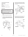
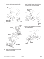
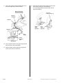
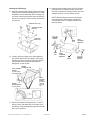
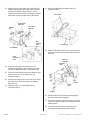
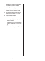
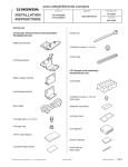
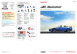
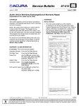
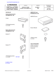
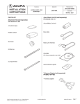
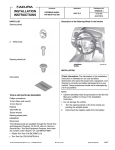
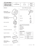
INSTALLATION
INSTRUCTIONS
Accessory
Application
CD CHANGER
ATTACHMENT KIT
2003 MDX
Publications No.
BII 24550
Issue Date
SEP 2002
PARTS LIST
CD Changer Attachment Kit:
P/N 08B26-S3V-200
5 Wire ties
(One not used)
Right base bracket
4 Washer-screws, 4 x 8 mm
2 Wire clips
Left base bracket
CD Changer (sold separately):
P/N 08A26-1B2-101
BUS Cable
CD changer
4 Flange bolts, 6 x 12 mm
4 Flange nuts
4 Washer-screws, 4 x 6 mm
(Not used)
Adhesive seal sheet
Black cushion tape
Locking covers
Right changer bracket
CD magazine
Left changer bracket
Owner’s Manual
Small wire tie
(Not used)
2 Gray cushion tapes
© 2002 American Honda Motor Co., Inc - All Rights Reserved.
BII 24550 (0209)
08B26-S3V-2000-91
1 of 7
TOOLS AND SUPPLIES REQUIRED
Flat-tip screwdriver
Phillips screwdriver
Ratchet
8 mm, 10 mm, and 12 mm Sockets
Shop towel
Diagonal cutters
8 mm and 10 mm Combination wrenches
4.
Remove the screws fastening the audio brackets,
then pull the audio unit out toward you. Unplug the
vehicle connectors and antenna lead from the rear
of the audio unit.
VEHICLE
HARNESS
INSTALLATION
Customer Information: The information in this
installation instruction is intended for use only by
skilled technicians who have the proper tools,
equipment, and training to correctly and safely add
equipment to your vehicle. These procedures should
not be attempted by “do-it-yourselfers.”
1.
ANTENNA
LEAD
RADIO
BRACKET
Make sure you have the anti-theft code for the radio,
then write down the frequencies for the preset
buttons.
2.
Disconnect the negative cable from the battery.
3.
Using a flat-tip screwdriver wrapped with a shop
towel, pry up on the clips and pull the radio panel
out toward you. Unplug the connectors and remove
the radio panel.
SCREW
5.
On the driver’s side of the vehicle, gently pull the
center console lower cover out toward you to
release the clips and remove the center console
lower cover. Take care not to damage the clips.
DRIVER’S
SEAT
CENTER CONSOLE
LOWER COVER
RADIO
PANEL
CLIP
CLIP
2 of 7
BII 24550 (0209)
© 2002 American Honda Motor Co., Inc - All Rights Reserved.
6.
Remove the driver’s seat front cover by pulling it
toward you. Take care not to damage the clips.
9.
Locate the slit in the floor carpet just under the
driver’s seat cushion, and pull the BUS cable 14-pin
connector out about 300 mm through the slit.
DRIVER’S
SEAT
SLIT in FLOOR
CARPET
about
300 mm
DRIVER’S SEAT
FRONT COVER
7.
CLIP
BUS CABLE
Route one end of the BUS cable from the radio
opening down through the center console.
DRIVER’S
SEAT
FRAME
10. Secure the BUS cable to the vehicle harness with a
wire tie in the area shown.
VEHICLE
HARNESS
BUS CABLE
14-PIN
CONNECTOR
RADIO
OPENING
BUS CABLE
WIRE TIE
VEHICLE
HARNESS
TAPE
BUS CABLE
BUS CABLE
8.
Continue routing the BUS cable along the center
console and the driver’s seat.
© 2002 American Honda Motor Co., Inc - All Rights Reserved.
BII 24550 (0209)
3 of 7
11. At the radio opening, adjust the BUS cable so it's
the same length as the vehicle harness.
14. Install the right and left base brackets into the holes
in the driver’s seat risers, and install two
6 x 12 mm flange bolts into each bracket. Do not
tighten the bolts yet.
Make the BUS cable
and vehicle harness
are the same length.
6 x 12 mm
FLANGE BOLTS (4)
VEHICLE
HARNESS
WIRE TIE
RIGHT
BASE
BRACKET
WIRE TIE
LEFT
BASE
BRACKET
BUS
CABLE
BLACK
CUSHION
TAPE
BUS CABLE
12. Secure the BUS cable to the vehicle harness with
three wire ties in the areas shown.
13. Attach the black cushion tape at the edge of the
center console in the area shown.
4 of 7
BII 24550 (0209)
© 2002 American Honda Motor Co., Inc - All Rights Reserved.
Installing the CD Changer
15. Carefully unpack the CD changer. Remove the three
shipping clips, and discard the shipping cover. Install
an adhesive seal (included with the CD changer kit)
over each of the three clips holes. Save the shipping
clips for your customer in the event the unit needs to
be serviced.
18. Install the right changer bracket on the CD changer
using two 4 x 8 mm washer-screws, and the two
wire clips. Install the left changer bracket on the CD
changer using two 4 x 8 mm washer-screws.
SHIPPING CLIPS (3)
NOTE: With the changer mounted in this location,
the locking covers do not indicate right and left
correctly. Mount the CD changer brackets in the
direction shown.
SHIPPING COVER
(Discard.)
4 x 8 mm
WASHERSCREW
SHIPPING
SEALS (3)
WIRE
CLIP
WIRE
CLIP
16. Visually check the position of the spring adjusting
pin on both sides of the CD changer. If the spring
adjusting pins are not in the horizontal (H) position,
move the pins to the horizontal (H) position by
sliding them up with an awl.
RIGHT
CHANGER
BRACKET
FRONT
LEFT
CHANGER
BRACKET
4 x 8 mm
WASHERSCREW
SPRING
ADJUSTING PIN
LEFT LOCKING
COVER
(included with
CD Changer kit)
RIGHT
LOCKING
COVER
(included
with CD
Changer
kit)
SPRING
ADJUSTING PIN
(H: Horizontal)
(V: Vertical)
17. Remove the adhesive backing from the “L” and “R”
locking covers, and attach them to the sides of the
CD changer. Align the diagonally opposite holes with
the H and V positions.
© 2002 American Honda Motor Co., Inc - All Rights Reserved.
BII 24550 (0209)
5 of 7
19. Attach one gray cushion tape to the rear of the CD
changer leaving half of the cushion tape extended
past the CD changer. Using scissors, cut the
cushion tape at the end of the CD changer. Fold the
ends down around the edges of the CD changer.
24. Connect the BUS cable connector to the CD
changer connector.
BUS CABLE
RIGHT BASE
BRACKET
FLANGE
NUT
LEFT BASE
BRACKET
GRAY
CUSHION
TAPE
CD CHANGER
CD CHANGER
25. Plug the BUS cable connector, the vehicle harness
connector, and the antenna lead into the rear of the
audio unit.
GRAY
CUSHION
TAPE
VEHICLE
HARNESS
ANTENNA
LEAD
20. Attach the other gray cushion tape to the CD
changer overlapping the other cushion tape. Fold
the cushion tape around the CD changer bracket.
21. Position the CD changer on the base brackets, and
tighten the four 6 x 12 mm flange bolts you
installed in step 14.
22. Install the four flange nuts on the ends of the studs
that extend from the base brackets, and tighten
them securely.
BUS
CABLE
AUDIO
UNIT
23. Tighten the four 6 x 12 mm flange bolts you
removed in step 14.
SCREW
26. Check that all wire harnesses are routed properly
and all connectors are plugged in.
27. Connect the negative cable to the battery. Enter the
customer’s radio anti-theft code, and reset the radio
station presets.
28. Check that the radio and the CD changer work
according to the appropriate owner’s manual.
6 of 7
BII 24550 (0209)
© 2002 American Honda Motor Co., Inc - All Rights Reserved.
NOTE: Whenever the battery is disconnected, the
driver's window AUTO function is disabled.
29. Start the engine. Push down on the driver's window
switch until the window is fully open.
30. Pull up on the driver's switch to close the window
completely, then hold the switch for 2 seconds.
31. Lower and raise the driver's window to check the
operation of the driver's window AUTO function.
32. Do the PCM idle learn procedure.
–
Make sure all electrical items are turned off.
–
Start the engine. Hold the engine speed at 3,000
rpm with no load (in Park or Neutral) until the
radiator fan comes on.
–
Let the engine idle for about 5 minutes with the
throttle fully closed and with all electrical items
off.
NOTE: If the radiator fan comes on during this step,
the time when it is operating must not be included in
the 5 minutes.
© 2002 American Honda Motor Co., Inc - All Rights Reserved.
BII 24550 (0209)
7 of 7